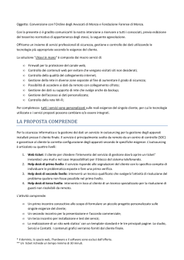
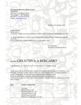
Soluzioni per il benessere ed il risparmio MANUALE D’USO ED D’INSTALLAZIONE INSTALLATION AND USER MANUAL Icool Pompe di Calore Monoblocco ad Alta Efficienza Prima di installare il climatizzatore leggere attentamente le Istruzioni www.finteksrl.com I prodotti elettrici ed elettronici di eventuale scarto dovranno essere disposti con i normali rifiuti domestici, ma smaltiti a norma di legge RAEE in base alle direttive Europee 2002/96/CE e successive modifiche 2003/108/CE, informandosi presso il Comune di residenza o presso il rivenditore nel caso in cui il prodotto venga sostituito con uno analogo. Possible wasted electrical or electronic devices/products should not be located together with normal domestic waste, but disposed according to the current WEEE law in compliance with the European Directive 2002/96/EC and following modifications 2003/108/EC. Please inform yourself at your local Fintek srl. Soc. Unipersonale Via Strozzi 6 – 47895 Domagnano RSM Tel/ fax +39 0549 901950 - +39 393 1808890 Cod. Ident. C.O.E. SM 05944 Cap Soc. 25.800 € int.vers Ric. Giur. Del 16/08/1996 Iscr Reg. Soc n° 1273 www.finteksrl.com [email protected] OPPURE ACQUISTARE UN IMBALLAGGIO INTEGRO PER IL TRASPORTO L’EVENTUALE MANCANZA DELL’IMBALLAGGIO ORIGINALE NON RENDERA’ TRASPORTABILE IL VS CLIMATIZZATORE CHE DOVRA’ ESSERE RECAPITATO A VS SPESE E A VS RESPONSABILTA’ PRESSO IL CENTRO ASSISTENZA AUTORIZZATO CONSERVARE I CARTONI E LE PARTI IN POLISTIROLO PER UN EVENTUALE ASSISTENZA IN GARANZIA, NB: QUALORA LA RIPARAZIONE NON FOSSE POSSIBILE IN LOCO. IL PRESENTE FOGLIETTO E’ PARTE INTEGRANTE DEL MANUALE D’USO ED INSTALLAZIONE "55&/;*0/& /#-&((&3&"55&/5".&/5&*-1"3"(3"'0 ."/65&/;*0/&'*-53* ITALIANO ,7$/,$12 ,1)250$=,21,*(1(5$/, &216(*1$'(// $33$5(&&+,2 ,O FRQGL]LRQDWRUH q LPEDOODWR LQ XQD VFDWROD GL DFDUWRQH FRQ SURWH]LRQL LQWHUQH SHU JDUDQWLUQH O LQWHUJULWj GXUDQWH LO WUDVSRUWR $OO LQWHUQR WURYHUHWH TXHVWR PDQXDOH FKH q SDUWH LQWHJUDQWH GHO FRQGL]LRQDWRUH H GHYH HVVHUH OHWWR DWWHQWDPHQWH ROWUH DG HVVHUH FRQVHUYWR LQ XQ OXRJRVLFXURHGDFFHVVLELOH$VVLFXUDWHYLFKHWXWWL LFRPSSRQHQHWLVLDQRFRQWHQXWLQHOODVFDWROD 029,0(17$=,21( P0 1 2 5 8 $RQVLGHUDWH SHQH LO SHVR GHO FRQGL]LRQDWRUH SULPD GL VSRVWDUOR R GL VROOHYDUOR3UHQGHWH WXWWH OH SUHFDX]LRQL QHFHVVDULH SHU QRQ DUUHFDUYL GDQQL ILVLFL H QRQ URYLQDUH LO FRQGL]LRQDWRUH 9L FRQVLJOLDPR GL WRJOLHUH LO FRQGL]LRQDWRUH GDOOD VFDWROD QHOOH LPPHGLDWH YLFLQDQ]H GL GRYH YHUUj HIIHWWXDWD O LQVWDOOD]LRQH 5LPXRYHWH OH EDQGH DGHVLYH GL SURWH]LRQH 1% &RQVHUYDWH OD VFDWROD SHU HYHQWXDOL IXWXWL LQWHUYHQWL GL DVVLVWHQ]D 3RQHWH DWWHQ]LRQH DJOL LPEDOOL LQ SODVWLFD SHU OD VLFXUH]]D GHO96EDPELQL /,67$$&&(6625,&2035(6, 7(/(&20$1'2 3257$7(/(&20$1'2 78%26&$5,&2&21'(16$ *5,*/,($63,5$=,21((638/6,21( 9,7,(7$66(//, /,%5(772,6758=,21, ',0$,1&$57$ 3$11(//23(578%,$63,5$=,21( 78%23(55,&$0%,2$5,$23=,21$/ ),/75,(/(775267$7,&,237=,21$/ 3 4 6 10 9 7 ',5(77,9$0$&&+,1(&(( ',5(77,9$%$66$7(16,21((02',),&$&(( ',5(77,9$&203$7,%,/,7$ (/(77520$*1(7,&$(0&&(( ',5(77,9$&((68//()),&,(1=$(1(5*(7,&$ ',5(77,9$&(:(( ',5(77,9$&(5R+6 -& 1*-& %&- 5&-&$0."/%0 $0/5&/(0/0 4045"/;& %"//04& (&55"5&-& /&(-* "1104*5* $0/5&/*503* 0 $0/5"55"5& -h&/5& 13&10450 "--04."-5*.&/50 ,7$/,$12 ,1)250$=,21,*(1(5$/, &$5$77(5,67,&+(7(&1,&+( iCOOL W ( 00) 2730(9300) 873 3.8 879 3. 8 350 48 12 . 5 P1 Fuse ( T6.3A) 1890 Installation bracket 43/ 95/19.5 Net weight ( Kg ) 40 Air inlet area Condenser outlet fan P2 Condenser inlet fan Fron panel /()9(5'( /('*,$//2 ,/ GLVSOD\ PRVWUD FRPWHPSRUDQHDPHQWH OH WHPSHUDWXUH DPELHQWH H OD WHPSHUDWXUD LPSRVWDWD GD WHOHFRPDQGR.'RSR DYHU FDPELDWR OD WHPSHUDWXUD GD WOF HVVD ODPSHJJLHUj SHU VHF, GRSRGLFKq YLVXDOL]]DUHWH OD WHPSHUDWXUD DPELHQWH SHU DOWUL VHF ILQLWR LO GLVSOD\ VL VSHJQHUj H VL ULDFFHQGHUj D VXFFHVVLYDPRGLILFD /('%/8 /('52662 8 22mm FLOOR 2000mm 40mm 435mm 283mm 65x28mm 220mm 46mm OBBLIGATORIO Tagliare l'isolante posteriore della macchina in questa posizione per allacciare la macchina alla rete elettrica senza l'utilizzo della spina shuko , e per la connessione alla rete MOD BUS ( optional ) Cut back insulating material in this position to connect the machine without power plug , or for MOD BUS connection ( Optional ) 200mm 515mm 585mm 955mm FLOOR 2000mm 220mm 200mm 168mm 23RWHWHVRVWLWXLUHLOFDYRFRPSOHWDPHQWHGDOOD SDUWHSRVWHULRUHGHOODPDFFKLQDYHGL)LJ3 7DJOLDWH O LVRODPHQWR H DFFRUGDWHYLDOPRUVHWWR1HOOD SDUWHVLQLVWUDVRWWRO HWLFKHWWD GL SRWHQ]D GHOOD PDFFKLQD WURYHUHWH XQ SRUWHOOLQR FRQ YLWL WRJOLHWHOH H ULPXRYHWH LO SRUWHOOLQR 6,67(0$',5,35(6$$5,$ (67(51$23=,21$/( A P31 'HQWUR WURYHUHWH OD PRUVHWWLHUD GHO FDYR GL DOLPHQWD]LRQH 5LFRUGDWH OH SRODULWj %OX1HXWUR 0DUURQH)DVH *LDOOR9HUGH7HUUD )LJ 3 5LIDWH LO SDVVDJJLR )LJ DO FRQWUDULR SHU ULFKLXGHUHFRUUHWWDPHQWHODPDFFKLQD B P33 /D PDFFKQD q GRWDWD GL XQ VLVWHPD RS]LRQDOH SHU OD ULSUHVD GHOO DULD HVWHUQD DWWUDYHUVR XQ WXERGDFP3RWUHWHFRVLFDPELDUHSXULILFDUH DXWRPDWLFDPHQWH O DULD DOO LQWHUQR GHO YRVWUR DPELHQWH )RUDWH FRQ XQD SXQWD GD PP LO PXUR QHOOD SRVL]LRQH LQGLFDWD QHOOD GLPD GL ILVVDJJLR LQ FDUWD ( LPSRUWDQWLVVLPR PDQWHQHUH XQD LQFOLQD]LRQH GL JUDGL QHO IRUR SHUHYLWDUHFKHGXUDQWHOHJLRUQDWHSLRYRVHXQD TXDQWLWjGLDFTXDSRVVDHQWUDUHQHOODPDFFKLQD P32 Screw N CO A B Screws D C DWWHQ]LRQHODPDFKLQDQRQGHYH HVVHUHLQVWDOODWDLQXQDODYDQGHULD $1&25$**,2'(/&21',=,21$725( 'RSR DYHU FXUD GL DYHU FRQWUROODWR OD WHQXWD GHL WDVVHOOL QHO PXUR H SUHSDUDWH OH FRQQHVVLRQL HOHWWULFKH H OR VFDULFR GHOOD FRQGHQVD ),* DSSHQGHWH LO FOLPDWL]]DWRUH DYHQGR FXUD GL LQILODUH FRUUHWWDPHQWH L YHQWLODWRUL VXL IRUL GL DHUHD]LRQH H LPPHGLDWDPHQWHLQVHULUHLWDVVHOOLFKHILVVHUDQQROD PDFFKLQD ILJ DO PXUR 6ROR FRVL VDUHWH VLFXUL FKHO DQFRUDJJLRVLDSHUIHWWDPHQWHULXVFLWR ,QVSH]LRQDWH DFFXUDWDPHQWH FKH QRQ FL VLDQR IHVVXUHIUDODPDFFKLQDHLOPXURHFKHODVWHVVDVLD SRVL]LRQDWDSHUIHWWDPHQWHLQ³%ROOD´ -hBQQBSFDDIJPEFWFFTTFSFQPTJ[JPOBUPJOVOMVPHP BDDFTTJCJMF -hBQQBSFDDIJPEFWFFTTFSFJOTUBMMBUPTFDPOEPMF OPSNBUJWFFMFUUSJDIFWJHFOUJ Fix with washer and nut P28 P29 P25 9&$92(/(775,&2,1'27$=,21( 0HOJBQQBSFDDIJPÒGPSOJUPVODBWPFMFUUSJDPDPO QSFTB4$)6$0-BTVBSJNP[JPOFDPNQSPNFUUFMB HBSBO[JB1 Concrete anchor P30 P26 P27 Power cord 1 .3 3(5=21(&/,0$7,&+(7(03(5$7((),*3 Splicing line Outdoor Indoor P21 6&$5,&2'(//$&21'(16$ 8QLWH LO WXER LQ GRWD]LRQH GHOOR VFDULFR FRQGHQVD SURYYHGHQGR D WRJOLHUH LO WDSSR LQ JRPPD FRPH LQ ILJ ,Q TXHVWR PRGR GUHQHUHWHODFRQGHQVDLQPRGRGDQRQFUHDUH QHVVXQSUREOHPDDOQHEXOL]]DWRUHP22). P22 Drainage pipe P23 2 6H YL WURYDWH LQ XQ DUHD FOLPDWLFD FDOGD R QRQ HFFHVVLYDPHQWH IUHGGD VFDULFDWH OD FRQGHQVD DOO HVWHUQR GLYHUVDPHQWH YL VXJJHULDPR GL VFDULFDUOD DOO LQWHUQR R VRWWRWUDFFLD RQGH HYLWDUH SRVVLELOL JKLDFFLDPHQWLLQYHUQDOL),*3 Outdoor Indoor Drainage pipe Hard terminal Soft terminal P24 'RSR DYHU SRVL]LRQDWR OH JUDWH ULSDVVDWH FRQ OD SLVWRODGHOVLOLFRQHSHUFKLXGHUHHYHQWXDOLEXFKL )LJ3 ILVVDJJLRGHOO LVRODQWHSODVWLFR 'RSRDYHUILVVDWROHJULJOLHSURYYHGHWHDFRVWUXLUH LO WXER SODVWLFR LVRODQWH IRUQLWR FRQ LO FRQGL]LRQDWRUH 6HPSOLFHPHQWH VWHQGHWHOR VX XQD VXSHUILFLH SLDQD H FRQ XQ WDJOLHULQR FRQIRUPDWH OD OXQJKH]]D GHO FRQGRWWR FRQVLGHUDQGR OD OXQJKH]]D GHO PXUR PHQR PP 2UD DUURWRODWHOR H LQVHULWHOR QHO IRUR VXOOD SDUHWHSRQHQGRDWWHQ]LRQHDOODOLQHDGLJLXQ]LRQH GHOOH GXH SDUWL LQ PRGR FKH QRQ VL VRYUDSSRQJDQRXWLOL]]DWHGHOQDVWURSHUXQLUOR T P15 iCOOL unit Wall thickness P18 77mm 30mm thickness P16 T Fan thickness External grating 500mm P17 628mm PLASTICSHEETWITHINSULATION P19 2.4 ),66$**,2'(,7$66(//, 310 ,QVHULUH L WDVVHOOL LQ FRUULVSRQGHQ]D GHL IRUL DSSHQD SUDWLFDWL FRQWUROODQGR FKH JOL VWHVVL DEELDQR WHQXWD 6H FLz QRQ VL YHULILFDVVH XWLOL]]DWH VLVWHPL GL ILVVDJJLR GLYHUVL R XQD UHVLQD DG DOWD WHQXWD 6L UDFFRPDQGR LO FRUUHWWR ),66$**,2 3(5 $66,&85$5(/81,7$$/0852 Concrete anchors 2. 6HLQYHFHLOFOLPDWL]]DWRUHH LQVWDOODWRLQ SRVL]LRQH LQDFFHVVLELOH GRYHWH ILVVDUH OH JUDWHGDOO LQWHUQR 0HWWHUHGHOVLOLFRQHDWWRUQRLOERUGRGHOODJUDWDFRPH LQILJHLQVHULUOHGDOO LQWHUQRYHUVRO HVWHUQR $VVLFXUDWHYLFKHHVVHVLDQREHQILVVDWHHGDVSHWWDWH XQDWWLPRFKHLOVLOLFRQHDEELDSUHVDVXOPXUR P10 P12 2.5 'RSR DYHU SUDWLFDWR L IRUL GL DVSLUD]LRQH HG HVSXOVLRQH ILVVDWH OH JUDWH LQ FRUULVSRQGHQ]D GHLIRUL 6H O DFFHVVR HVWHUQR q VHPSOLFHILVVDUH OH JUDWH GDOO HVWHUQR FRQ WUH SLFFROL WDVVHOOL GD PP WHQHQGR OHVWHVVHLQSRVL]LRQHYHUWLFDOH P13 (S 9(',P11 ) P14 P11 6&$5,&2'(//$&21'(16$P8) )25268//$3$5(7( 6HVWDWHIRUDQGRODSDUHWHDSLDQRWHUUD DVVLFXUDWHYLGDDYHUPHVVRLQVLFXUH]]DOD]RQD HVWHUQDGRYHSUDWLFDUHLOIRURSRWUHEEHURFDGHUH GHWULWLSRWHQ]LDOHPWHSHULFRORVL )25,(67(51,3) 4XHVWDRSHUD]LRQHGRYUHEEHHVVHUHHIIHWWXDWDGD SHUVRQDOH VSHFLDOL]]DWR H XWLOL]]D]QGR XWHQVLOL DGDWWL TXDOL FDURWDWULFL DG DFTXD FRQ SXQWH GLDPDQWDWHGLGLDPHWURPP 48(672 &/,0$7,==$725( +$ 812 6&$5,&2 &21'(16$ $8720$7,&2 3(5 48(672 9, &+,(',$02 ', 6(*8,5( /( ,1',&$=,21, 62772&21$77(1=,21( )RUDWHFRQXQDSXQWDGDPPLQFRUULVSRQGHQ]D GL TXDQWR PRVWUDWR VXOOD GLPD GL FDUWD $QFKH SHU TXHVWR IRUR VL FRQVLJOLD GL PDQWHQHUH XQD LQFOLPD]LRQH GL PLQLPR ,Q TXHVWD PDQLHUH SHUPHWWHUHWH DOOD FRQVHQVD GL GHIOXLUH OLEHUDPHQWH VHQ]DFDXVDUHSRVVLELOLULHPSLPHQWLGHOODYDVFKHWWD GLUDFFROWDHSUREDELOLWUDFLPDPHQWL P8 P6 6, 5$&&20$1'$ ', 7(1(5( 81$ ,1&/,1$=,21( ', )25$785$ ', $/0(129(',),*3 ,O VLVWHPD GL FRQGHQVD HVWHUQR H SUDWLFDWR QDWXUDOPHQWH LQ SUHVHQ]D GL FOLPD WHPSHUDWR R TXDQGR OH WHPSHUDWXUH HVWHUQH QRQ VRQR HVWUHPDPHQWHULJLGH P9 3° INCLINATION WALLB RACKETH OLES (P 9) P7 ,17(512 (67(512 )RUDWH LO PXUR SHU LQL]LDUH D FUHDUH L VXSSRUWL SHU O DQFRUDJJLR GHOOD PDFFKLQD DO PXUR XQD YROWD SRVL]LRQDWDVXOORVWHVVRFRVLFRPHGHVFULWWRQHOODGLPD GLILVVDJJLRLQQHUHWWRVLUDFFRPDQGDVHPSUHGLILVVDUH FRQ OH YLWL LQ GRWD]LRQH OD PDFFKLQD DO PXUR 8OOL]]DWH SXQWHGDPP 3. USO E MANUTENZIONE ITALIANO 3.1 ICONE DEL TELECOMANDO Significato Auto Significato Velocita' ventilatore Raffreddamento Direzione aria Deumidificazione Timer off Ventilazione Timer on Riscaldamento Notturno Orologio Non in uso 3.2 FUNZIONI DEL TELECOMANDO 1 3. USO E MANUTENZIONE ITALIANO 3.3 MODO RISCALDAMENTO 3.4 MODO RAFFREDDAMENTO 1 3. USO E MANUTENZIONE ITALIANO 3.5 MODO DEUMIDIFICAZIONE 3.6 MODO VENTILAZIONE 1 3. USO E MANUTENZIONE ITALIANO 3.7 MODO NOTTURNO 3.8 MODO AUTOMATICO 21 1 3. E 3.9 SPEGNIMENTO CON IL TIMER Sequenza delle operazioni. Fare riferimento al punto 3.1 e 3.2 1 2 3 4 5 3.10 ACCENSIONE CON IL TIMER Sequenza delle operazioni. Fare riferimento al punto 3.1 e 3.2 1 2 )0$187(1=,21(),/75, ,O FOLPDWL]]DWRUH SXz HVVHUH GRWDWR GL GXH WLSL GL ILOWUL XQ SUHILOWUR LQ SODVWLFD DQWLSROYHUH FKH DQGUj UHJRODUPHQWH SXOLWR H ODYDWR FRQ DFTXD WLHSLGD H GHWHUJHQWHDOPHQRXQYROWDRJQLGXHVHWWLPDQHGL IXQ]LRQDPHQWRHXQ)LOWUR(OHWWURVWDWLFR),17(. DQWLEDWWHULFR DQWLDOOHJLFR FKH GHYH HVVHUH VRVWLWXLWR REEOLJDWRULDPHQWH RJQL PHVL SHU DFTXLVWDUOR ZZZILOWULSHUFRQGL]LRQDWRULFRP HVVR QRQ GRYUD 0$, HVVHUH ODYDWR PD VROR VRVWLWXLWR LQWHJUDOPHQWH FRQVLGHUDWH FKH q SRWHQ]LDOPHQWH FDULFR GL EDWWHUL XWLOL]]DWH OH SUHFDX]LRQL QHFHVVDULH $0.&130$&%&3& UPHMJFSF MhBMJNFOUB[JPOF EBM DMJNBUJ[[BUPSF BQSJSF JM QBOOFMMP GSPOUBMF DPO MF NBOJ UPHMJFSF JM QSFGJMUSP EBMMB TVB TFEF DPO EFMJDBUF[[B QSPDFEFSF BMMB QVMJ[JB OPO QSJNB EJ BWFS SJNPTTP JM GJMUSP FMFUUSPTUBUJDP BJ DBSCPOJ "TDJVHBUFMPCFOFFSJNQJB[[BUFJMGJMUSPFMFUUSPTUBUJDP WBDBNCJBUPVOBWPMUBPHOJNFTJ P39 P40 16-*;*"%&--"."$$)*/" 5PHMJFSF MhBMJNFOUB[JPOF EFMMB NBDDIJOB 1VMJSF MB TVQFSGJDJF EFMMB NBDDIJOB DPO VO QBOOP VNJEP TFO[B OFTTVO EFUFSHFOUF OPO VTBSF QBOOJ USPQQP VNJEJ F TQVHOF JNCFWVUF FTTF QPTTP EFQPTJUBSF BDRVB DIF B MVOHP BOEBSF QPUSFCCF DPNQSPNFUUFSF MB TJDVSF[[B EFMMhVOJUË P38 Filter holder P41 ACTIVE CARBON FILTER (OPTIONAL) ( P41) 5BMJ GJMUSJ TPOP PQ[JPOBMJ F QPUSFCCFSP OPO FTTFSF JODMVTJTFOPOMPGPTTFSPQPUSFUFBDRVJTUBSMJEBMTJUP XXXGJMUSJQFSDPOEJ[JPOBUPSJDPN -B GVO[JPOF EJ RVFTUJ GJMUSJ Ò EJ SFOEFSF MhBSJB QJá SFTQJSBCJMF QPJDIÒ MB MPSP GVO[JPOF Ò EJ USBUUFOFSF UVUUF MF JNQVSJUBh DIF J OPSNBMJ GJMUSJ BOUJQPMWFSF OPO QPTTPOP USBUUFOFSF RVBMJ NVGGF TQPSF BMMFHFOJ JO HFOFSBMF *OGBUUJ UBMJGJMUSJ TPOP BOUJCBUUFSJDJ BOUJBMMFSHJDJ F BOUJMFHJPOFMMB &TTJ %&70/0 &44&3& "440-65".&/5& 404565*5* & /0/ -"7"5* MhBDRVB FMJNJOB JM MPSP FGGFUUP 3.13$11(//2)5217$/( P36 4XDQGR LO FOLPDWL]]DWRUH LQL]LD D IXQ]LRQDUH LO SDQQHOOR IURQWDOH VL DSULUj FLUFD VHFRQGL GRSR LQL]LHUDQQR D IXQ]LRQDUH LO FRPSUHVVRUH HG L YHQWLODWRUL GXUDQWH O XVR LO SDQQHOOR IURQWDOH UHVWUHUj DSHUWR$OORVSHJQLPHQWRSULPDVLIHUPHUj LO FRPSUHVVRUH SRL L YHQWLODWRUL H VXFFHVVLYDPHQWH FRPH FKLXVXUD GHOO RSHUD]LRQHLOSDQQHOOR 3 ,16(5,0(172(6267,78=,21('(//(%$77(5,( P37 $SULUHLOFRSHUFKLRHLQVHULUHOH EDWWHULHVHFRQGRSRODULWiGHVFULWWR I,QVHULUHOHEDWWHULH$$$SH]]L 5LSRVL]LRQDUHLOFRSHUFKLR $FFHQGHUH LO FRQGL]LRQDWRUH GDO WHOHFRPDQGRDWWUDYHUVRLOSXOVDQWHGL 212)) VH QHVVXQD LFRQD FRPSDUH QHO GLVSOD\ YHULILFDUH GL DYHU PHVVR OH EDWWHULHFRUUHWWDPHQWH 3. 16 SOLUZIONE PROBLEMI ENGLISH POSITIONING THE AIR CONDITIONER 2 4 FASTENING THE BRACKET 2 5 FITTING THE GRATINGS 7 2 6 FIXING PLASTIC SHEET AND INSULATION 8 2 7 CONNECTING DRAINAGE PIPE 9 2 8 FITTING THE AIR CONDITIONER ON BRACKET 2 9 POWER CORD CONNECTION 2 10 FRESH AIR SYSTEM( OPTIONAL) 10 11 FRONT PANEL FUNCTION 3.13 FRESH AIR FUNCTION (OPTIONAL) 3 . 14 3 . 15 19 1. 1 INTRODUCTION Please note: Don' t dispose of any packaging until the installation of the air conditioner is completed. After having removed the packing, check that all the content is intact and complete. (See list of accessories) . In the event of missing parts, contact your retailer. This air conditioner has been designed to cool or heat the air of a room and should only be used for this purpose. The manufacture can not be held liable for damage caused to property or injury to persons or animals due to incorrect installation, regulation and maintenance or improper use. This air conditioner contains R410A refrigerant, at the end of its life, the disposal of this air conditioner must be accordance with the strict regulation governing the recycling of this product, please operate with caution during the disposal. Please contact your local authority for regulation advice. Don't switch on before having totally assembled the air conditioner and before installing in its correct operating position. Before starting the appliance, check that it is correctly earthed, according to the legislation in force in the country concerned. 1.2 IMPORTANT SAFETY INSTRUCTIONS When using electrical appliance, basic safety precautions should always be followed: Don't place objects on the products or allow objects to obstruct the inlet or outlet openings. Extreme care should be taken when any product is used by,or near children and pets, and whenever the products is left operating and unattended. Please note: Before operating the product, remove the air conditioner from its packaging and check if it is in good condition. Do not let child play with the package, for example the plastic bags. Do not operate any products with a damaged cord or plug, or after the air conditioner malfunctions, has been dropped,or damaged in any manner. Return the air conditioner to an authorised service centre for examination and repair to avoid a hazard. Do not attempt to repair or adjust any electrical or mechanical functions on this air conditioner as this may void warranty, contact your service engineer. Always operate the product from a power source of the same voltage, frequency and rating as indicated on the product identification plate. This air conditioner is not intended for use in wet or damp locations. Do not place the air conditioner near an open flame, cooking or heating appliance, or hot surface. Do not let the power cord hand over the edge of a table or counter. Arrange the power cord away from an area where it may be tripped over. Never place the power cord under a carpet or rug. Do not operate the air conditioner in areas where petrol, paint, or other flammable liquid are used or stored. Do not carry out any cleaning or maintenance or access internal parts until the air conditioner has been disconnected from the mains electricity supply. Do not alter the safety or regulating devices without the permission and instructions of the air conditioner manufacturer. Do not pull, remove or twist the electric cable connected to the air conditioner, even if disconnected from the mains electricity supply avoid prolonged direct contact with the flow of the air from the air conditioner and the room being closed with no ventilation for a long period of time. Repair or maintenance work must be carried out by a service engineer or by qualified technicians in compliance with the instructions given in this booklet. Do not alter the appliance, since hazardous situations could be created while the manufacture of the appliance will not be liable for any damage or injury caused. This instruction booklet is an integral part of the appliance and should therefore be carefully preserved and always accompany the appliance in the event of transfer to another owner or user or another installation engineer. Should the booklet be damaged or lost, please request an additional. iCOOL 2.3 W 2346(8000) (8 ) 350 50 12 . 5 P1 Fuse ( T6.3A) 1900 Installation bracket 43/95/19.5 Net weight ( Kg ) 40 Air inlet area Condenser outlet fan P2 Condenser inlet fan Fron panel The display will show both setting temperature and ambient temperature. After adjusting the setting temperature, the setting temperature will flash 15 times on the display, then the display will show the ambient temperature for 70 seconds. After that, the display will be off until next adjustment. ,7$/,$12 ,1)250$=,21,*(1(5$/, &216(*1$'(// $33$5(&&+,2 ,O FRQGL]LRQDWRUH q LPEDOODWR LQ XQD VFDWROD GL DFDUWRQH FRQ SURWH]LRQL LQWHUQH SHU JDUDQWLUQH O LQWHUJULWj GXUDQWH LO WUDVSRUWR $OO LQWHUQR WURYHUHWH TXHVWR PDQXDOH FKH q SDUWH LQWHJUDQWH GHO FRQGL]LRQDWRUH H GHYH HVVHUH OHWWR DWWHQWDPHQWH ROWUH DG HVVHUH FRQVHUYWR LQ XQ OXRJRVLFXURHGDFFHVVLELOH$VVLFXUDWHYLFKHWXWWL LFRPSSRQHQHWLVLDQRFRQWHQXWLQHOODVFDWROD 029,0(17$=,21( P0 1 2 5 8 $RQVLGHUDWH SHQH LO SHVR GHO FRQGL]LRQDWRUH SULPD GL VSRVWDUOR R GL VROOHYDUOR3UHQGHWH WXWWH OH SUHFDX]LRQL QHFHVVDULH SHU QRQ DUUHFDUYL GDQQL ILVLFL H QRQ URYLQDUH LO FRQGL]LRQDWRUH 9L FRQVLJOLDPR GL WRJOLHUH LO FRQGL]LRQDWRUH GDOOD VFDWROD QHOOH LPPHGLDWH YLFLQDQ]H GL GRYH YHUUj HIIHWWXDWD O LQVWDOOD]LRQH 5LPXRYHWH OH EDQGH DGHVLYH GL SURWH]LRQH 1% &RQVHUYDWH OD VFDWROD SHU HYHQWXDOL IXWXWL LQWHUYHQWL GL DVVLVWHQ]D 3RQHWH DWWHQ]LRQH DJOL LPEDOOL LQ SODVWLFD SHU OD VLFXUH]]D GHO96EDPELQL /,67$$&&(6625,&2035(6, 7(/(&20$1'2 3257$7(/(&20$1'2 78%26&$5,&2&21'(16$ *5,*/,($63,5$=,21((638/6,21( 9,7,(7$66(//, /,%5(772,6758=,21, ',0$,1&$57$ 3$11(//23(578%,$63,5$=,21( 78%23(55,&$0%,2$5,$23=,21$/ ),/75,(/(775267$7,&,237=,21$/ 3 4 4 6 10 9 7 ',5(77,9$0$&&+,1(&(( ',5(77,9$%$66$7(16,21((02',),&$&(( ',5(77,9$&203$7,%,/,7$ (/(77520$*1(7,&$(0&&(( ',5(77,9$&((68//()),&,(1=$(1(5*(7,&$ ',5(77,9$&(:(( ',5(77,9$&(5R+6 -& 1*-& %&- 5&-&$0."/%0 $0/5&/(0/0 4045"/;& %"//04& (&55"5&-& /&(-* "1104*5* $0/5&/*503* 0 $"/5"55"5& -h&/5& 13&10450 "--04."-5*.&/50 To maintain the best performance from your air conditioner, prevent breakdowns or hazards,you must position it correctly.Please follow the guidelines and instruction below in full, as failure to do so could cause potential installation problems. The air conditioner must be installed on an exterior wall that has access to the out side with a minimum of 2 meters clearance to the outside. (See image P3) The air conditioner must be fitted leaving room all around as illustrated in the paper template. The wall on which the air conditioner is installed must be sturdy and able to withstand the weight fo the air conditioner. Fasten the template to the wall once the following guidelines have been thoroughly checked. Do not drill any holes until you are completely confident that there are no obstacles in the area you wish to drill and there are no obstructions, which could be hidden by the construction of the wall, for example: electrical wiring, water&gas pipes or supporting lintels or beams. Ensure that a spirit level is used, as the air conditioner must be level. Follow the installation instructions in full. spirit level P4 After determining the best place for installation as described above,please check to ensure that the wall can be drilled in the chosen area without interfering with other structures or installations ( beams, piers, pipes, wires, etc. ) . Please also ensure that there are no obstacles on the outside of the wall , which may obstruct air circulation through the drilled holes , for example : ( plants and their leaves , slats or panelling , drain pipes , overflows and gratings , etc . ) . Any obstruction could interfere with the correct performances of the air conditioner . Outdoor Fasten the template to the wall taking care to check the distance from the floor or ceiling. Use a pilot drill to mark the centre of each core hole to be drilled. ( See image P5) P3 Indoor 2m 2 - 2 . 2m 2m P5 22mm FLOOR 2000mm 40mm 435mm 283mm 65x28mm 220mm 46mm OBBLIGATORIO Tagliare l'isolante posteriore della macchina in questa posizione per allacciare la macchina alla rete elettrica senza l'utilizzo della spina shuko , e per la connessione alla rete MOD BUS ( optional ) Cut back insulating material in this position to connect the machine without power plug , or for MOD BUS connection ( Optional ) 200mm 515mm 585mm 955mm FLOOR 2000mm 220mm 200mm 168mm P6, 7,8,9 Please note:If you are drilling the hole above ground floor level, please ensure that an area has been secured and while the holes are drilled the outside area is supervised, until drilling has been completed. INTAKE AND OUTLET HOLES( P6) This operation should be carried out using the proper tools ( diamond tip or core borers drills with high twisting torque and adjustable rotation speed). Find the holes center drilled before, u se a core boring head having a diameter of 200mm to drill the two holes for intake an d outlet the air. DRAINAGE HOLE (P8) This air conditioner has a system to drain the condensate moisture automatically. Please read carefully the following instruction. Drill a hole through the wall measuring 30mm in diameter in the position shown in the paper template, marked the center before. Drainage occurs by gravity. For this reason, it is essential for the drain line to have a minimum downward inclination at least 3 degrees throughout its length. With this solution, you can drain the condensate moisture to a suitable place to do not cause any problems to your neighbours. P8 P6 This drainage method is more common use, and the discharge pipe goes outside where there is no problem to connect or to discharge it, this solution is OK for hot country and normal cold temperature outside. WALL BRACKET HOLES (P9) ( See image P7) P9 3° INCLINATION P7 Drill the holes for anchoring the fastening bracket to the wall using preferably the 26 holes with 8mm diameter showed in black on the paper template. As the unit is installed on high wall,it is recommended that all the holes should be fixed with anchor bolts. 2.4 ANCHORS 10 2. When the air conditioner is installed in the high space, and impossible to reach the gratings from outdoor side, you could fix the gratings from inside. Insert the concrete anchors into the holes for the unit,and tighten them inside the wall. The anchor bolts provided require 10 mm holes; the wall should be inspected to determine if provided bolts are useful or if it is necessary to use a different anchorage. The manufacture is not liable in case of underestimation of the structural consistency of the anchorage made at the time of installation. Concrete anchors Put the silicon gel around of the soft grating, like Fig17.Then fold the outer grating in half, insert your arm inside the hole with the grating. Let the grating unfold and pull the grating toward you. With a little patience and manipulation, the 2 gratings will fit the end of the holes. (See P12,13,14) P10 P12 2.5 After drilling the holes, the plastic gratings supplied with air conditioner need to be fitted on the wall. 1. When gratings is easy accessibility, you could fix the gratings from outside, it is recommended to fasten it to the wall with wall plugs and screws with a diameter of 6mm, and keep the fins in vertical position. ( See P11 ) P13 P14 P11 7 After fixing the outside grating,we could inject more gel inside the space between the grating and wall. (See P15,16) 2.6 FIXING PLASTIC SHEET AND INSULATION After fixing the outside grating,insert the plastic sheet with insulation supplied with the conditioner into the holes.The sheets must be 107mm shorter than the thickness of the wall.(See P18) Use an ordinary cutter for the operation . ( See P19 ) Wall thickness iCOOL unit T P15 P18 77mm Fan thickness 30mm External grating thickness P16 T 500mm The black silicon gel is just for reference, we could use white or transparent color gel to fix the outdoor grille.(See P17) P17 628mm PLASTIC SHEET WITH INSULATION P19 Roll the sheet and insert it into the hole , paying attention to the splicing line , which must always face up wards . (See P21 ) 1. When the machine is installed in normal climate or hot area, we can connect the drainage pipe to outside, with a proper place. ( See P23) Splicing line Outdoor Indoor P21 7 CONNECTING DRAINAGE PIPE Connect the drain pipe ( from rubber terminal ) to the air conditioner ( back side ) after unplugged the black rubber cup ( see P22 ). With this solution, you can drain the condensate moisture to a suitable place to do not cause any problems to your neighbours. P22 Drainage pipe P23 2. When the machine is installed in very cold area, the water in drainage pipe is frozen easily in winter, we could connect the drainage pipe inside the wall, and connect with a proper place.( See P24) Outdoor Indoor Drainage pipe Hard terminal Soft terminal P24 8 The appliance shall not be installed the laundry. ANCHORS After checking again that the fastening anchors are securely fastened to the wall, and that any necessary preparations for electric connection and condensate drainage have been made, fasten the air conditioner to its supporting anchors. ( See P25) Lift it up by holding the sides at the bottom, slightly insert the outside fan rings into the two big holes on the wall. ( See P26) The air conditioner can now be pushed firmly against the wall, then lift the unit and make sure the anchors and unit match well. ( See P27) Inspect carefully the installation to make sure that the insulating back panel must fit firmly against the wall and there are no fissures at the back of the air conditioner. The appliance must be positioned so that the plug is accessible. The appliance shall be installed in accordance with national wiring regulations. Fix with washer and nut P28 Fixing two nuts with top of the machine, to make sure the unit is installed well. ( See P28, 29) P29 P25 9 POWER CORD CONNECTION 1. For every unit, there would be a power cord on the left side( P30). Connect the plug with the socket, and operate the unit. Concrete anchor P30 P26 P27 Power cord 10 2. For aesthetic purpose during the installation, we could change the power cord connection solution with another way. -- On the back of the unit , there is a hole for the wire connection , you can cut the back insulation material , then connect the additional wire accordingly . Just be careful with the operation and do not damage the wires . About the hole dimension , you can check the paper template .( See P31 ) -- Take out the cable clip by plier from the side plate , and remove the power cable from unit . ( See P32 C ) - - Connect the wires passed through the hole of back plate . -- Block window cap and fix rating label again . -- Block the hole of power cable with a rubber cap supplied with the air conditioner . (See P32 D ) 2 . 10 FRESH AIR SYSTEM ( OPTIONAL ) P31 --On left side, there is an operation window under the rating label. Remove the rating label, unscrew 2pcs screws by driver, then take out the window cap.( See P32 A ) - - A wire connection block is inside the box , brown color is live wire , blue color is neutral wire , yellow - green is earth wire . -- Unscrew the 3pcs screws , remove the wires from connection block .( See P32 B ) A P32 B Screw P33 There is fresh air system in the back of the unit, and fresh air pipe is 50mm. The air conditioner would change room air automatically. In this way, new clean and fresh air will be intaken to the room. Same time, the air conditioner performance would be lower.(See P33 A) N CO A B Screws D C Drill a hole through the wall measuring 52mm in diameter in the position shown in the paper template, marked the center before. It is essential for the hole line to have a minimum downward inelination at least 3 degrees throughout its length. With this solution, in the rainy day, the water could not come to inside.(See P33 B) 3. 3 HEATING MODE 3. 4 COOLING MODE 3. 5 DRY MODE 3. 6 FAN MODE Press the ON/OFF button " ", switch on the air conditioner, it will run by memory mode. Press the MODE button " " set up the mode to fan " ", the air conditioner will run in fan. Press UP " " or DOWN " " button, to adjust the setting up temperature. Press the FAN SPEED button " " , set up the fan speed. is low speed, is middle speed, is high speed, ( flashing) is auto speed. Fan auto fan, the speed is choosen by the difference of room temperature and setting temperature. Room temperature- setting temperature>5℃, high speed. Room temperature- setting temperature>3℃, middle speed. Room temperature- setting temperature>1℃, low speed. Press the ON/OFF button " " , switch off the air conditioner. Next time when this button is pressed, the air conditioner will operates in this mode by memory. 3. 7 SLEEP MODE 3. 8 AUTO MODE 3. 9 TIMER OFF FUNCTION 3. 10 TIMER ON FUNCTION 16 3. 11 FRONT PANEL FUNCTION P34 When the unit starts working, the front panel and flap would open completely at first. About 15- 20 seconds later, indoor fan and compressor would work as mode setting, and front panel would stay with open position when the unit is working. During front panel opening period, the indoor fan would not work, and there is no air coming out from the air conditioner. If unit is closed, indoor fan would stop first, then front panel and flap would close completely again. 3. 12 INSTALL AND CHANGE THE BATTERY P35 - - Open the cover of battery, hold the hook and lightly pull up. - - Insert the battery ( AAA, 2pcs) , the positive must be same with the mark on the plastic surface. - - Reinstall the cover of battery. Inspection: If press ON/OFF button " ", no icons are displayed, please install the battery again. 3. 13 FRESH AIR FUNCTION (OPTIONAL) There are 3 positions with the fresh system, roll the frame with arrow direction, OPEN, CLOSE and CLEAN would be shown one by one. Fresh air filter should be cleaned regularly to keep the fresh air flow smooth. Take out the filter as arrow direction, wash it( no use hot water) and only when it is dried replace it in same way. ATTENTION: 1.Do not use the air conditioner without fileter. 2.Do not use the fresh air system in heating mode. Fresh air system Open position OPEN Close position CLOSE Clean position CLEAN P36 3.14 MAINTENANCE (P37,38, 39) The filter should be regularly cleaned to keep the air conditioner running efficiently. Clean the filters every two weeks. How to proceed: - - Disconnect the air conditioner from the electrical supply . - - Open the front panel by hand . - - Take the filter holder ( See P37 ), take out the filter grating from the slot . ( See P38 ) . -- Proceed to wash them ( not hot water ) and only when they are dried replace them in the same way . ( See P39 ) P38 P39 ATTENTION: Do not use the air conditioner without filters as it could seriously damage the air conditioner. - - Disconnect the air conditioner from the electrical supply. -- Wipe external surfaces clean with a damp cloth only. -- Do not use an abrasive cloth or solvents, as this may damage the surfaces. -- Do not use excessively wet cloths or sponges, as water stagnation could damage the air conditioner and compromise safety. P37 Filter holder P40 ACTIVE CARBON FILTER (OPTIONAL) (P40) The unit maybe includes active carbon filter, which not only has the function of eliminating suspended matters that a common mechanical filter has, but also can eliminate foreign matters such as free chlorine, odors, colors and toxic matters that are difficult to filter out by using conventional approaches. With active carbon filter, the room air would be fresh and good for the body health. Is advisable to change them every three months, because it is not possible to wash or clean them. 3. 15 PROBLEM SOLVING PROBLEM POSSIBLE CAUSES - The air conditioner does not work. - The air conditioner does not refrigerate the room. - Strange smell in the room. Water drips from the air conditioner. - The remote control does not work. - The air conditioner does not work for 3 min when switched on. POSSIBLE SOLUTIONS 1.Wrong setting of the timer/ Check it. 2. Problems on the power supply/ Call the service center. 3.The filter could be dirty/ Clean it. 4. The room temperature is too high/ Wait until the temperature goes down. 5.The temperature is not properly set/ Check it. 6. The grids could be obstructed/ Check and remove the eventual obstacles. - Dampness in the room, coming from walls, carpets, furnishing or similar. -Wrong installation of the air conditioner. - Wrong connection of the drainage pipe. - Exhausted batteries. - Wrong insertion of the batteries inside the remote control. - Protection of the conditioner.Wait for 3 min and the air conditioner will start to work again. If the supply cord damaged, it must be replaced by manufacturer or its service agent or a similarly qualified person in order to avoid a hazard. The max operation temperature for the air conditioner: ( max cooling: outdoor DB43℃/ WB26℃,indoor DB32℃/WB23℃; min heating: outdoor DB-5℃/WB-6℃, indoor Db20℃) This appliance is not intended for use by persons (including children) with reduced physical, sensory or mental capabilities, or lack of experience and knowledge, unless they have been given supervision or instruction concerning use of the appliance by a person responsible for their safety. Children should be supervised to ensure that they do not play with the appliance. 20 Soluzioni per il benessere ed il risparmio Fintek srl via B. Strozzi, 6 - 47895 Domagnano Repubblica di San Marino Tel./Fax +378 (0549) 901950 Cell +39 393 1808890 [email protected] Visita il nostro sito e scopri tutti i nostri prodotti www.finteksrl.com
Scaricare