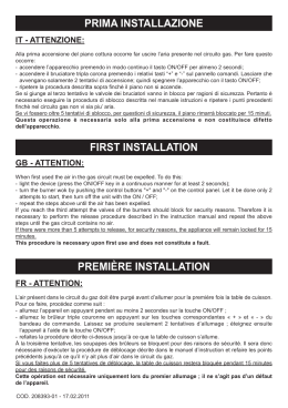
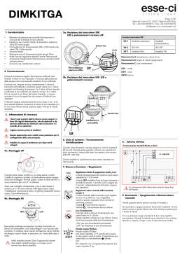
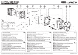
FCX M MA AN NU UA ALLEE D DII FFU UN NZ ZIIO ON NA AM MEEN NTTO O • • D DIIR REEC CTTIIO ON NS S FFO OR R U US SEE M MA AN NU UEELL D DEE FFO ON NC CTTIIO ON NN NEEM MEEN NTT • • B BEED DIIEEN NU UN NG GS SA AN NLLEEIITTU UN NG G VENTILCONVETTORI FAN COIL VENTILO-CONVECTEURS GEBLÄSEKONVEKTOREN Sostituisce - Replace Remplace - Ersetzt: 64560.39/0005 IFCXFX 0201 64560.52 INDICE • INDEX • INDEX • INHALTSVERZEICHNIS FCX - A Funzionamento • Operation • Fonctionnement • Betrieb FCX - ACB Funzionamento • Operation • Fonctionnement • Betrieb FCX - ACT Funzionamento • Operation • Fonctionnement • Betrieb Utilizzo • Use Utilisation • Betrieb Caratteristiche di funzionamento • Operation Caracteristiques des fonctionnement • Einsatzcharakteristik Configurazione • Setting Configuration • Konfiguration Autotest USI IMPROPRI • IMPROPER USES • USAGES IMPROPES • UNSACHGEMÄßER GEBRAUCH MANUTENZIONE • MEINTENANCE • ENTRETIEN • WARTUNG PROBLEMA - PROBABILE CAUSA - SOLUZIONE ROBLEM - PROBABLE CAUSE - REMEDY PROBLEME - CAUSE PROBABLE - SOLUTION PROBLEM - MÖGLICHE URSACHE - ABHILFE 3 4 5 6 7 8 9 10 11 12 13 14 FUNZIONAMENTO FCX - A • FCX - A OPERATION FONCTIONNEMENT DU FCX - A • BETRIEB DER FCX - A Commutatore manuale (versione A) Manual switch (A version) Commande standard (version A) Standard Fernbedienung (version A) a) Per accendere/spegnere il ventilconvettore: Commutare la posizione del selettore superiore. To turn on/off the fan coil: Shift the upper button. On the remote panel with Pour allumer/eteindre le ventilconvecteur: Pouser le bouton du haut. Sur le panneau avec Einschalten/Ausschalten des Gebläsekonvektors: Die Stellung des oberen Schiebers ändern. Auf der mit b) Per scegliere la velocità del ventilatore To select fan coil speed Pour choisir la vitesse du ventilateur Ventilatorgeschwindigkeit wählen FFC CX X - A A 3 FFC CX X - A AC CB B 4 FUNZIONAMENTO FCX - ACB • FCX - ACB OPERATION FONCTIONNEMENT DU FCX - ACB • BETRIEB DER FCX - ACB Termostato elettronico a funzioni ridotte (versione ACB) Reduced-function electronic thermostat (ACB version) Thermostat électronique à fonctions réduites (version ACB) Elektronischer Thermostat mit eingeschränkten Funktionen (version ACB) a) Per accendere/spegnere il ventilconvettore: 1) Aprire la griglia di destra del ventilconvettore per accedere al pannello comandi. 2) Commutare la posizione del selettore superiore: si accende/spegne la spia rossa. To turn on/off the fan coil: 1) Open the fancoil right grille to reach the control panel. 2) Change over the upper button: red goes on/off. Pour allumer/éteindre le ventiloconvecteur: 1) Ouvrir la grille à droit du ventiloconvecteur pour atteindre le panneau commandes. 2) Pousser le bouton du haut: le témoin rouge s’allume/s’éteint. Einschalten/Ausschalten des Gebläsekonvektors: 1) Um den thermostats zu betätigen, Das rechte Gitter öffnen. 2) Die obene taste rüecken: leuchtet/erlöscht die rote Lampe auf. b) Per scegliere il funzionamento - To select operating mode Pour choisir le mode fonctionnement - Betriebsmodus anwählen Inverno • Winter Hiver • Winter Estate • Summer Eté • Sommer c) Per scegliere la velocità del ventilatore To select fan coil speed Pour choisir la vitesse du ventilateur Ventilatorgeschwindigkeit wählen d) Per impostare la temperatura: ruotare la manopola verso la zona blu per un’azione di raffreddamento e verso quella rossa per un’azione di riscaldamento. La spia gialla vicino alla manopola indica il tipo di funzionamento (spenta se l’unità non è in funzione, accesa se è in funzionamento). To set the temperature: turn the knob towards the blue zone in order to cool or towards the red zone in order to heat. The yellow pilot light near the knob shows the operation mode (off, if the unit is not working; on, if it is working). Pour programmer la température: tourner le bouton vers la zone bleue pour une action de refroidissement et vers la zone rouge pour une action de chauffage. Le voyant jaune près du bouton indique le type de fonctionnement (il est éteint si l’unité n’est pas en marche; il est allumé si l’unité est en fonction). Für die Temperatureinstellung: den Bedienungsknopf gegen den blauen Bereich für den Kühlbetrieb und gegen den roten Bereich für den Heizbetrieb drehen. Die gelbe Kontrollampe in der Nähe des Bedienungsknopfes zeigt die Betriebsart an (kein Aufleuchten bei ausgeschalteter Einheit, ein Aufleuchten im Betrieb). FUNZIONAMENTO FCX - ACT • FCX - ACT OPERATION FONCTIONNEMENT DU FCX - ACT • BETRIEB DER FCX - ACT Il pannello comandi è alloggiato sotto lo sportellino con griglia a destra o a sinistra del ventilconvettore (fig. 4). Il pannello può essere protetto da manomissioni, bloccando con una vite lo sportellino di copertura. Il termostato di regolazione controlla il funzionamento del ventilconvettore per mantenere nell’ambiente la temperatura impostata. Il modo di funzionamento in riscaldamento o in raffreddamento, avviene in modo automatico (cambio stagione) e dipende dalla temperatura dell’acqua circolante nell’impianto. Il pannello comprende (fig. 1): –(A) selettore acceso-spento e modo di ventilazione; –(B) selettore della temperatura; –(C) led indicatore del modo di funzionamento (blu, rosso e fucsia); –(D) led giallo indicatore di richiesta ventilazione (o anomalie di funzionamento se lampeggiante). The control panel is located under the door with grid on the left or right-hand side of the fancoil (fig. 4). To prevent tampering with unit controls, secure the door with a screw. The thermostat controls the operation of the fancoil, which is regulated to maintain the temperature setting. The unit operating mode switches automatically between heating and cooling (season change), depending on the temperature of the water in the system. The panel features (fig. 1): -(A) ON/OFF and ventilation mode selector switch; -(B) temperature selector switch; -(C) operating mode LED indicator lamp (blue, red and pink); -(D) ventilation request yellow LED lamp (also indicates operating fault when flashing). Le panneau de commande se trouve sous le volet à grille, à droite ou à gauche du ventilo-convecteur (fig. 4). Le panneau peut être protégé contre les manipulations en bloquant le volet de couverture à l'aide d'une vis. Le thermostat de régulation contrôle le fonctionnement du ventilo-convecteur, de façon à maintenir constante la température programmée dans la pièce. Le mode de fonctionnement Chauffage ou Rafraîchissement se fait automatiquement (changement de saison) et il dépend de la température de l'eau qui circule dans l'installation. Le panneau comprend (fig. 1): -(A) sélecteur marche-arrêt et mode de ventilation; -(B) sélecteur de la température; -(C) led indiquant le mode de fonctionnement (bleu, rouge et fuchsia); -(D) led jaune indiquant une demande de ventilation (ou des anomalies de fonctionnement si elle clignote). Das Bedienteil ist unter der Klappe mit Ausströmgitter rechts oder links am Gebläsekonvektor angeordnet (Abb. 4). Es kann durch Sichern der Klappe mit einer Schraube gegen unbefugtes Verstellen geschützt werden. Der Temperaturregler steuert den Betrieb des Gebläsekonvektors so, dass die eingestellte Raumtemperatur konstant gehalten wird. Die Einschaltung der Betriebsart Heizen oder Kühlen erfolgt automatisch (Umschaltung von Heizen/Kühlen) in Funktion der Temperatur des in der Anlage zirkulierenden Wassers. Auf dem Bedienteil sind folgende Elemente angeordnet (Abb. 1): -(A) Wahlschalter Ein/Aus und Gebläsebetrieb; -(B) Temperaturschalter; -(C) Anzeige-Led der Betriebsart (blau, rot und fuchsia); -(D) Gelbe Led zur Anzeige der Anforderung des Gebläsebetriebs (oder Betriebsstörungen bei Blinken). B - C A Fig.1 + D V1 =Velocità minima Minimun fan speed Vitesse minimale Mindestgeschwindigkeit V2 =Velocità media Mediun fan speed Vitesse moyenne Mittlere Geschwindigkeit V3 =Velocità massima Maximun fan speed Vitesse maximale Höchstgeschwindigkeit FFC CX X - A AC CTT 5 FFC CX X - A AC CTT 6 UTILIZZO (FCX-ACT) USE (FCX-ACT) COMANDI: CONTROLS: Selettore della Velocità (A) OFF Il ventilconvettore è spento. Può però ripartire in modalità Caldo (funzione Antigelo) se la temperatura ambiente diventa inferiore a 8°C e la temperatura dell’acqua è idonea, in questo caso il led rosso lampeggia. AUTO Il termostato mantiene la temperatura impostata cambiando la velocità del ventilatore in Modo Automatico, in funzione della temperatura ambiente e di quella impostata. A Il termostato mantiene la temperatura impostata mediante cicli di accensione e spegnimento, utilizzando rispettivamente la velocità minima, media o massima del ventilatore. Selettore della Temperatura (B) Consente di impostare la temperatura desiderata (fig. 3). La temperatura corrispondente al selettore B impostato nella posizione centrale (fig. 5), dipende dal modo di funzionamento attivo (Caldo 20°C, Freddo 25°C, Antigelo 8°C). C Le differenze di temperatura massima e minima rispetto alla posizione centrale sono +8°C e -8°C + - Speed selector switch (A) OFF The fancoil is off, though will restart in heating mode (antifreeze function) if room temperature drops below 8°C and water temperature is suitable; in this case, the red LED lamp will flash. AUTO The thermostat maintains temperature of the setting by adjusting fan speed in automatic mode, according to the room temperature and the temperature setting. The thermostat maintains the temperature of the setting by on-off cycles, using minimum, medium and maximum fan speeds as required. Fig. 2 - + Temperature selector switch (B) Use to make the required temperature setting (fig. 3). The temperature at the central position (fig. 5) will depend on the current operating mode (Heating 20°C, Cooling 25°C, Antifreeze 8°C). D The maximum temperature deviations from the central position are +8°C and -8°C Season change Cambio stagione The FCX-ACT fancoil automatically sets to Il ventilconvettore FCX- ACT imposta automatiHeating or Cooling mode according to the temFig. 3 camente il funzionamento a Caldo o a Freddo perature of the water circulating through the in funzione delle temperature dell’acqua nell’impianto; unit. In special cases, season change can be made by adjuper impostazioni particolari è possibile il cambio stagione sting the temperature selector switch. agendo sul selettore temperatura. Visualizzazioni luminose Il led C cambia di colore per indicare il modo di funzionamento attivo: ROSSO Caldo (riscaldamento), BLU Freddo (raffreddamento), FUCSIA lampeggiante indica che l’acqua nell’impianto non ha ancora raggiunto la temperatura idonea per abilitare la ventilazione, GIALLO acceso indica che la richiesta di ventilazione è attiva; lampeggiante indica una anomalia di funzionamento della sonda ambiente (Modo Emergenza). Displays The LED indicator lamp C changes colour to indicate the current operating mode: RED Heating, BLUE Cooling, PINK When flashing, water in unit has not yet reached temperature required to enable ventilation, YELLOW Ventilation request is activated. When flashing, an ambient probe operating fault has been detected (Emergency mode). Fig. 4 UTILISATION (FCX-ACT) GEBRAUCH (FCX-ACT) COMMANDES: Bedienteile: Sélecteur de la Vitesse (A) OFF Le ventilo-convecteur est éteint. Il peut toutefois repartir en mode Chauffage (fonction Antigel) si la température ambiante s'abaisse au-dessous de 8°C et que la température de l'eau est appropriée; dans ce cas, la led rouge se met à clignoter. Drehzahl-Wahlschalter (A) OFF Der Gebläsekonvektor ist ausgeschaltet. Er wird wieder in der Betriebsart Heizen (Einfrierschutz-Funktion) eingeschaltet, sobald die Raumtemperatur unter 8 °C abfällt und die Wassertemperatur dies zulässt. In diesem Fall blinkt die rote Led-Diode. + - AUTO Le thermostat maintient la température programmée en modifiant la vitesse du ventilateur en Mode Automatique, en fonction de la tempéra- A ture ambiante et de la température programmée. AUTO Der Temperaturregler hält die eingestellte Temperatur durch Regelung der Gebläsedrehzahl im Automatikbetrieb in Funktion von Raumtemperatur und eingestelltem Temperatur-Sollwert konstant. Le thermostat maintient la températuFig. 2 re programmée en exécutant des Der Temperaturregler hält den eingecycles d'allumage et d'arrêt et en utilisant stellten Temperatur-Sollwert durch zykrespectivement la vitesse minimale, moyenne ou maximale lisches Ein- und Ausschalten konstant, er setzt dazu entweder die du ventilateur. unterste, die mittlere oder die höchste Gebläsedrehzahl ein. Sélecteur de la Température (B) Il permet de programmer la température désirée (fig. 3). La température correspondant au sélecteur réglé sur la position centrale (fig. 5) dépend du mode B de fonctionnement actif (Chaud 20°C, Froid 25°C, Antigel 8°C). Les différences de température maximale et C minimale par rapport à la position centrale sont +8°C et -8°C. + - Temperaturschalter (B) Dieser Schalter dient zur Einstellung der gewünschten Raumtemperatur (Abb. 3). Die Temperatur bei Mittelstellung des Wahlschalters (Abb. 5) ist von der jeweils aktiven Betriebsart abhängig (Heizen 20 °C, Kühlen 25 °C, Einfrierschutz 8 °C). Die Differenz der höchsten und niedrigsten D Temperatur zur Mittelstellung beträgt +8 °C und -8 °C. Changement de saison Umschaltung Kühl-/Heizbetrieb Le ventilo-convecteur FCX- ACT règle automatiDer Gebläsekonvektor FCX-ACT schaltet selbquement le fonctionnement en Chauffage ou sttätig in Funktion der Wassertemperaturen in Fig. 3 Rafraîchissement en fonction de la température der Anlage die Betriebsart Heizen oder Kühlen de l'eau présente dans l'installation; pour des réglages partiein. Für spezielle Einstellungen kann die Umschaltung von culiers, le changement de saison est possible en agissant sur Kühl-/Heizbetrieb mit dem Temperaturschalter vorgenomle sélecteur de température. men werden. Visualisations lumineuses La led C change de couleur pour indiquer le mode de fonctionnement actif: ROUGE Chaud (chauffage), BLEU Froid (rafraîchissement), FUCHSIA Si la led clignote, elle indique que l'eau présente dans l'installation n'a pas encore atteint la température appropriée pour valider la ventilation, JAUNE allumée, la led indique que la demande de ventilation est active; elle clignote pour indiquer une anomalie de fonctionnement de la sonde ambiante (Mode Urgence). Riscaldamento • Heating Chaud • Warm Raffreddamento • Cooling Froid • Kalt 20°C + C FROST PROTECTION 8°C 25°C - 12°C Leuchtanzeigen Die Led-Diode C zeigt die jeweils aktive Betriebsart durch eine Farbänderung an: ROT Heizen (Heizung); BLAU Kühlen (Kühlung); FUCHSIA Durch Blinken wird angezeigt, dass die Wasserfüllung der Anlage noch nicht die zur Einschaltung des Gebläses erforderliche Temperatur erreicht hat.; GELB Zeigt durch Leuchten an, dass der Betrieb des Gebläses angefordert wurde. Blinken zeigt eine Funktionsstörung des Raumfühlers an (Notbetrieb). D 28°C - 17°C C + D 33°C 8°C + C D 8°C Fig. 5 FFC CX X - A AC CTT 7 FFC CX X - A AC CTT 8 CARATTERISTICHE DI FUNZIONAMENTO I ventilconvettori FCX-ACT sono forniti pronti a funzionare in configurazione standard, ma consentono all’installatore di adeguarli alle necessità specifiche dell’impianto con accessori dedicati e personalizzando le funzioni agendo sui Dip-Switch interni (vedi IMPOSTAZIONI DIP-SWITCH e figg. 12 e 13). La risposta ai comandi è immediata, tranne casi particolari. Tipologie d’impianto I ventilconvettori della serie FCX-ACT sono progettati per impianti a 2 tubi, nelle varianti: - senza valvola; - con valvola a 2 vie (sonda acqua a valle della valvola); - con valvola a 3 vie (sonda acqua a monte della valvola). Ventilazione La ventilazione a tre velocità può essere comandata sia manualmente con selettore in posizione V1, V2 e V3 (il ventilatore è utilizzato con cicli di acceso-spento sulla velocità selezionata), oppure automaticamente con selettore in posizione AUTO (la velocità del ventilatore è gestita dal termostato in funzione delle condizioni ambientali). Per impianti con valvola e installazione Sonda Acqua a monte della valvola è possibile un ritardo (ventilazione ritardata fino ad un massimo 2’40”) tra accensione valvola ed abilitazione ventilatore (preriscaldamento scambiatore). Cambio stagione Il termostato cambia stagione automaticamente. Il cambio stagione avviene in base alla temperatura dell’acqua rilevata nell’impianto. In funzione delle settaggio dei Dip è possibile avere due modi di cambio stagione dal lato acqua: - con il solo controllo della temperatura minima/massima; - con il controllo della temperatura minima/massima ed il preriscaldamento della batteria (ventilazione ritardata fino ad un massimo di 2’40”). Solo per impianti particolari con sonda acqua a valle oppure valvola a 2 vie, il cambio stagione avviene dal lato aria, agendo sul selettore di temperatura; questa impostazione permette di poter utilizzare il ventilconvettore in impianti preesistenti con valvola a 2 vie, ma è sconsigliata in quanto riduce la facilità d’uso del termostato elettronico (la visualizzazione dello stato di funzionamento Caldo/Freddo tramite led risulta alterata, dipende dalla temperatura selezionata e dalla temperatura dell’aria nell’ambiente ). Controlli sulla temperatura dell’acqua Il termostato abilita la ventilazione solamente se la temperatura dell’acqua è idonea al modo Caldo o Freddo. Le soglie di abilitazione 35°C o 39°C a caldo e 17°C o 22°C a freddo sono configurabili tramite i Dip-Switch. Il pannello comandi segnala la situazione in cui la temperatura dell’acqua non sia adeguata al modo di funzionamento impostato, tramite il lampeggio altermato sul led C del colore fucsia con i colori rosso o blu relativi al modo attivo . Nel caso sia installata la valvola a 3 vie la sonda acqua SW (di serie) dev’essere sostituita con l’accessorio SW3 il cui bulbo deve essere posizionato sul tubo di mandata a monte della valvola. Comando valvola La valvola può essere controllata in due modalità: - ottimizzata: sfrutta la capacità del ventilconvettore a Caldo di erogare calore anche con ventilazione spenta, e a Freddo di avere una ventilazione continua mantenendo il controllo della temperatura ambiente tramite la valvola; - normale: la valvola apre o chiude in corrispondenza dell’accensione o spegnimento del ventilatore. Modo Emergenza In caso di avaria della sonda ambiente SA il termostato entra in modalità Emergenza, indicata dal lampeggiare del led (D) giallo. In questa condizione il termostato si comporta nel modo seguente: - con selettore (A) in posizione OFF la valvola acqua è chiusa ed il ventilatore spento. - con selettore (A) in posizione AUTO, V1, V2 e V3 la valvola acqua è sempre aperta ed il ventilatore esegue dei cicli di acceso - spento; in questa situazione la potenza erogata dal terminale viene comandata maualmente tramite il selettore (B): ruotando verso destra la durata del ciclo di Acceso aumenta; ruotando verso sinistra la durata diminuisce. OPERATION FCX-ACT fancoils are delivered ready to operate in standard configuration, though can be adjusted by the installation technician to specific requirements by means of dedicated accessories and configuration of functions at the internal dipswitches (see DIP SWITCH CONFIGURATION and figures 12 + 13). Response to controls is immediate, except in special cases. Unit types FCX-ACT fancoils are designed for twin-tube units, in the following types: - without valve; - with 2-way valve (water probe below valve); - with 3-way valve (water probe above valve). Ventilation Ventilation speed can be controlled either manually by setting the selector switch to position V1, V2 or V3 (the fan operates in on-off cycles according to the speed selected), or automatically when the selector switch is set to the AUTO position (fan speed is controlled by the thermostat according to room temperature detected). In the case of units with water probe above the valve, an operating delay (maximum time 2'40") can be set between valve start and fan enable (exchanger preheating). Season change The thermostat changes seasonal operation automatically. Season change takes place according to the water temperature detected in the unit. According to the dipswitch settings, two types of season change (water side) are possible: - with minimum/maximum temperature control only; - with minimum/maximum temperature control and coil preheating (fan operation delay maximum 2'40"). In the case of special units with water probe below the valve or fitted with 2-way valve, season change takes place from the air side, through operation of the temperature selector switch. Though this setting allows use of the fancoil in pre-existing 2way valve plants, it is not recommended, given that it hampers the operation of the electronic thermostat (the Heating/Cooling mode status display by LED is altered, depending on the temperature selected and the room air temperature). Water temperature controls The thermostat only enables fan operation when the water temperature is suitable for Heating or Cooling mode. The enabling thresholds 35°C or 39°C (heating) and 17°C or 22°C (cooling) can be configured as required by means of the dipswitches. If the water temperature is not suitable for the operating mode selected, LED lamp C on the control panel flashes alternately pink, red and blue next to the relative mode. If a 3-way valve is installed, replace the water probe SW (standard accessory) with the accessory SW3. Position the bulb of the latter accessory on the delivery line above the valve. Valve control La valvola può essere controllata in due modalità: - optimised: this mode exploits the capacity of the fancoil (Heating) to supply heat even when fan operation has been shut down; during Cooling, ventilation continues for control of room temperature by the valve. - normal: the valve opens or closes, depending on whether the fan starts up or shuts down. Emergency mode In the event of fault in the ambient probe SA, the thermostat sets to Emergency mode, indicated by the flashing of the yellow LED lamp (D). In this condition, the thermostat operates as follows: - with selector switch (A) in OFF position: water valve is closed and fan off; - with selector switch (A) in AUTO, V1, V2 or V3 position: the water valve remains open and the fan performs on - off cycles; in this case, the power supplied by the terminal is controlled manually by means of the selector switch (B): rotate the switch to right to increase cycle duration, or to the left to reduce it. CARACTERISTIQUES DE FONCTIONNEMENT Les ventilo-convecteurs FCX-ACT sont fournis prêts à fonctionner en configuration standard, mais ils permettent à l'installateur de les adapter aux besoins spécifiques de l'installation avec des accessoires spécifiques et en personnalisant les fonctions en agissant sur les commutateurs dip internes. (voir REGLAGES COMMUTATEURS DIP et fig. 12 et 13). La réponse aux commandes est immédiate, à l'exception des cas particuliers. Types d'installation Les ventilo-convecteurs de la série FCX-ACT sont conçus pour les installations à 2 tubes, dans les variantes : - sans vanne; - avec vanne à 2 voies (sonde de l'eau en aval de la vanne); - avec vanne à 3 voies (sonde de l'eau en amont de la vanne). Ventilation La ventilation à trois vitesses peut être commandée manuellement, avec le sélecteur sur la position V1, V2 et V3 (le ventilateur est utilisé avec des cycles de marche-arrêt à la vitesse sélectionnée), ou automatiquement, avec le sélecteur sur la position AUTO (la vitesse du ventilateur est gérée par le thermostat en fonction des conditions ambiantes). Pour les installations munies d'une vanne et avec Sonde Eau installée en amont de la soupape, un retard est possible (ventilation retardée jusqu'à un maximum de 2'40") entre la mise en marche de la vanne et la validation du ventilateur (préchauffage de l'échangeur). Changement de saison Le thermostat change automatiquement de saison. Le changement de saison a lieu en fonction de température de l'eau mesurée dans l'installation. En fonction des réglages des Dip, il est possible d'avoir deux modes de changement de saison sur le côté eau : - uniquement avec le contrôle de la température minimale/maximale; - avec le contrôle de la température minimale/maximale et le préchauffage de la batterie (ventilation retardée jusqu'à un maximum de 2'40"). Uniquement pour les installations particulières munies d'une sonde de l'eau en aval ou d'une vanne à 2 voies, le changement de saison se fait sur le côté air en agissant sur le sélecteur de température. Ce réglage permet de pouvoir utiliser le ventilo-convecteur dans des installations préexistantes avec vanne à 2 voies. Cela est pourtant déconseillé, dans la mesure où cela réduit la facilité d'emploi du thermostat électronique (la visualisation de l'état de fonctionnement Chauffage/Rafraîchissement au moyen de la led est faussée et dépend de la température sélectionnée et de la température de l'air ambiant). Contrôles de la température de l'eau Le thermostat valide la ventilation uniquement si la température de l'eau est appropriée au mode Chauffage ou Rafraîchissement. Les seuils de validation de 35°C ou 39°C en chaleur et de 17°C ou 22°C en rafraîchissement se configurent au moyen des commutateurs dip. Le panneau de commande signale la situation où la température de l'eau n'est pas appropriée au mode de fonctionnement programmé, par le clignotement sur la led C de la couleur fuchsia avec le rouge ou le bleu relatif au mode actif. Si l'installation est munie d'une vanne à 3 voies, la sonde de l'eau SW (de série) doit être remplacée par l'accessoire SW3 dont le bulbe doit être positionné sur le tuyau de refoulement situé en amont de la vanne. Commande de la vanne La vanne peut être contrôlée de deux manières différentes - optimisée: mode recourant à la capacité du ventilo-convecteur en Chauffage de fournir de la chaleur même si la ventilation est éteinte et, en Rafraîchissement, d'assurer une ventilation continue tout en maintenant le contrôle de la température ambiante au moyen de la vanne; - normale: la vanne s'ouvre ou se ferme à la mise en marche ou à l'arrêt du ventilateur. Mode Urgence En cas de panne de la sonde de température ambiante SA, le thermostat se met en mode Urgence, ce qui est indiqué par le clignotement de la led (D) jaune. Dans cette condition, le thermostat se comporte de la manière suivante : - Le sélecteur (A) étant sur la position OFF, la vanne eau est fermée et le ventilateur est éteint. - Le sélecteur (A) étant sur la position AUTO, V1, V2 et V3, la vanne d'eau est toujours ouverte et le ventilateur exécute des cycles de marche - arrêt; dans cette situation, la puissance fournie par le terminal est commandée manuellement au moyen du sélecteur (B) : en le tournant vers la droite, la durée du cycle Marche augmente; en le tournant vers la gauche, cette durée diminue. EINSATZCHARAKTERISTIK Die Gebläsekonvektoren FCX-ACT werden betriebsbereit in Standardkonfiguration geliefert. Der Installateur kann sie durch spezielle Zubehörteile auf die jeweiligen Anforderungen der Anlage abstimmen und deren Funktionen kundenspezifisch mit den internen DIP-Schaltern programmieren (siehe EINSTELLUNG DER DIP-SCHALTER und Abb. 12 u. 13). Die Schaltantwort auf Befehle erfolgt außer in speziellen Fällen verzögerungsfrei. Anlagenausführungen Die Gebläsekonvektoren der Serie FCX-ACT sind für Zweileitungsanlagen mit folgenden Varianten konzipiert: - ohne Ventil; - mit Zweiwegeventil (Wassertemperaturfühler hinter dem Ventil); - Dreiwegeventil (Wassertemperaturfühler vor dem Ventil). Gebläse Das dreistufige Gebläse kann wahlweise manuell mit Wahlschalter in den Stellungen V1, V2 und V3 (Betrieb des Gebläses durch zyklisches Ein-/Ausschalten mit der gewählten Drehzahl) bzw. automatisch mit Wahlschalter in der Stellung AUTO betrieben werden (Regelung der Gebläsedrehzahl über den Temperaturregler in Funktion des Raumklimas). Bei Anlagen mit Ventil und Anordnung des Wassertemperaturfühlers vor dem Ventil kann eine Verzögerungszeit (Verzögerung des Gebläsebetriebs um max. 2 Min u. 40 Sek.) zwischen Ventilumschaltung und Freigabe des Gebläses (Vorwärmen des Wärmeaustauschers) eingestellt werden. Umschaltung von Kühl-/Heizbetrieb Der Regler führt die Umschaltung der Betriebsarten Kühlen/Heizen automatisch durch. Die Umschaltung von Kühl-/Heizbetrieb erfolgt in Funktion der Temperatur der Wasserfüllung der Anlage. In Funktion der Einstellung der DIP-Schalter sind zwei Arten der Umschaltung von Kühl-/Heizbetrieb möglich: - Nur Kontrolle der Mindest-/Höchsttemperatur; - Kontrolle der Mindest-/Höchsttemperatur und Vorwärmen des Wärmeaustauschers (Gebläsebetrieb bis max. 2 Min u. 40 Sek. verzögert). Nur bei speziellen Anlagen mit Wassertemperaturfühler hinter dem Ventil oder Zweiwegeventil wird die Umschaltung von Kühl/Heizbetrieb luftseitig mit dem Temperaturschalter geschaltet. Diese Einstellung ermöglicht die Verwendung des Gebläsekonvektors in bestehenden Anlagen mit 2-wege-Ventil, wird jedoch nicht empfohlen, da sie die Bedienungsfreundlichkeit des elektronischen Reglers einschränkt (die Anzeige der Betriebsart Kühlen/Heizen mittels LedDioden ist abweichend, sie richtet sich nach der gewünschten Raumtemperatur sowie der effektiven Raumlufttemperatur). Kontrolle der Wassertemperatur Der Regler gibt den Gebläsebetrieb nur frei, wenn die Wassertemperatur für die Betriebsarten Heizen oder Kühlen geeignet ist. Die Freigabe-Schwellwerte betragen 35 °C bzw. 39 °C für Heizen und 17 °C bzw. 22 °C für Kühlen, sie werden über DIP-Schalter konfiguriert. Auf dem Bedienteil wird durch abwechselndes Blinken der fuchsiafarbenen Led C in den Farben Rot und Blau (je nach aktiver Betriebsart) angezeigt, wenn die Wassertemperatur nicht zur gewünschten Betriebsart passt. Falls ein Dreiwegeventil installiert ist, muss der Wassertemperaturfühler SW (Standardversion) durch Zubehörteil SW3 ersetzt werden, dessen Kugel an der Vorlaufleitung vor dem Ventil montiert wird. Ventilsteuerung Das Ventil kann auf zwei Arten angesteuert werden: - Optimierter Betrieb: Hierbei wird die Fähigkeit des Gebläsekonvektors genutzt, in heißem Zustand auch bei ausgeschaltetem Gebläse Wärme abgeben zu können, und in kaltem Zustand durch Regelung der Raumtemperatur über das Ventil eine kontinuierliche Lüftung aufrechtzuerhalten. - Normalbetrieb: Das Ventil öffnet bzw. schließt bei Ein- und Ausschaltung des Gebläses. Notbetrieb Bei Ausfall des Raumfühlers SA schaltet der Regler auf Notbetrieb um und zeigt dies durch Blinken der gelben Led (D) an. In diesem Zustand ist die Schaltlogik des Reglers wie folgt: - Bei Wahlschalter (A) auf OFF sind das Wassermengenventil geschlossen und das Gebläse ausgeschaltet. - Bei Wahlschalter (A) in Stellung AUTO, V1, V2 oder V3 ist das Wassermengenventil geöffnet und das Gebläse führt zyklische Ein-/Ausschaltungen durch. In diesem Fall wird die Leistungsabgabe des Innengeräts von Hand über Wahlschalter (B) geregelt. Drehen nach rechts verlängert die Dauer der Einschaltung, Drehen nach links verkürzt sie. FFC CX X - A AC CTT 9 FFC CX X - A AC CTT 10 CONFIGURAZIONE FCX-ACT• FCX-ACT SETTING • CONFIGURATION FCX-ACT • KONFIGURATION FCX-ACT OFF ON Fig. 6 IMPOSTAZIONI DIP-SWITCH Da eseguire in fase di installazione solo da personale specializzato. Agendo sui Dip-Switch (figg. 6 e 7) all’interno del termostato otterremo le seguenti funzionalità: (Per un corretto funzionamento i Dip 1 e 2 devono avere la stessa impostazione). Dip 1 (Default OFF ) Valvola di intercettazione: -se assente impostare OFF -se presente impostare ON Dip 2 (Default OFF ) Posizione della sonda temperatura acqua: -con sonda a valle della valvola o valvola 2 vie impostare OFF, -con sonda a monte della valvola o valvola 3 vie impostare ON -la combinazione Dip.1 ON con Dip.2 OFF è sconsigliata, può trovare applicazione solo in caso di installazione su impianti che utilizzano solo 2 vie preesistenti. Dip 3 (Default OFF) Gestione valvola: -per Valvola Ottimizzata impostare OFF -per Valvola Normale impostare ON Dip 4 (Default OFF) Correzione Sonda a Caldo per compensare il surriscaldamento della strutttura metallica: -correzzione ottimizzata impostare OFF -correzzione fissa impostare ON Dip 5 (Default OFF) Abilitazione modo Caldo in base alla temperatura dell’acqua: -per modo Caldo Normale (39°C) impostare OFF -per modo Caldo Ridotto (35°C) impostare ON Dip 6 (Default OFF) Abilitazione modo Freddo in base alla temperatura dell’acqua: -per modo Freddo Normale (17°C) impostare OFF -per modo Freddo Ridotto (22°C) impostare ON DIPSWITCH CONFIGURATION Configuration of dipswitches must only be carried out by qualified personnel during unit installation. Adjust the dipswitches (figures 6 + 7) inside the thermostat for the following functions: (Dip 1 and 2 must have the same configuration for a correct functioning). Dipswitch 1 (Default OFF ) Shut-off valve: - if not fitted, set to OFF - if fitted, set to ON Dipswitch 2 (Default OFF ) Water temperature probe: - if probe is below valve or 2-way valve is fitted, set to OFF - if probe is above valve or 3-way valve is fitted, set to ON Combination of Dip.1 ON with Dip.2 OFF is not recommended (used only for installation on two units using only pre-existing 2-way valves). Dipswitch 3 (Default OFF) Valve control: - for Optimised valve, set to OFF - for Normal valve, set to ON Dipswitch 4 (Default OFF) Probe (Heating) correction to compensate overheating of metal structure: - for optimised correction, set to OFF - for fixed correction, set to ON Dipswitch 5 (Default OFF) Enable Heating mode according to water temperature: - for Normal Heating mode (39°C), set to OFF - for Reduced Heating (35°C), set to ON Dipswitch 6 (Default OFF) Enable Cooling mode according to water temperature: - for Normal Cooling (17°C), set to OFF - for Reduced Cooling (22°C), set to ON FFC CX X - A AC CTT 11 CONFIGURAZIONE FCX-ACT • FCX-ACT SETTING • CONFIGURATION FCX-ACT • KONFIGURATION FCX-ACT Valvola di intercettazione assente No shut off valve OFF 1 ON * Vanne d'interception absenté Keine Absperrventil Sonda Acqua sullo scambiatore o valvola a 2 vie Temperature water on exchanger or on 2-way valve * Sonde eau sur l'échangeur ou vanne à 2 voies Wasserfühler auf Wärmetauscher oder 2-Wege Ventil Gestione valvola ottimizzata Optimised valve control * Gestion vanne optimisée Optimaler Ventilkontrolle Correzione Sonda ottimizzata Optimised probe correction * Correction sonde optimisée Normaler Heizbetrieb Abilitazione Caldo Normale Enable standard set heating * Validation chaleur normale Normaler Heizbetrieb Abilitazione Freddo Normale Enable standard set cooling * Validation rafraîchissement normal Normaler Kühlbetrieb 2 3 4 5 6 Abilitazione Freddo Ridotto Enable reduced set cooling Validation rafraîchissement réduit Reduzierter Kèhlbetrieb Abilitazione Caldo Ridotto Enable reduced set heating Validation chaleur réduit Reduzierter Heizbetrieb Correzione Sonda fissa Standard probe control Correction sonde fixe Standardkorrektur des Fühlers Gestione valvola normale Standard valve control Gestion vanne normale Standardkorrektur des Fühlers Sonda Acqua a Monte della valvola o valvola a 3 vie Temperature probe before valve or 3-Way valve Sonde eau en a mont de la vanne ou vanne à 3 voies Wasserfühler vor Ventil oder 3-Wege Ventil Valvola di intercettazione presente Shut off valve is present Présence de la vanne d'interception Absperrventil anwesend * = Impostazioni di fabbrica Factory settings Configurations de l'usine Werkseinstellung REGLAGES DES COMMUTATEURS DIP A faire exécuter au cours de l'installation uniquement par du personnel spécialisé. En agissant sur les commutateurs dip (Fig. 6 et 7) situés à l'intérieur du thermostat, on obtient les fonctions suivantes: (Pour un fonctionnement correct Dip 1 et 2 doivent être dans la même position). Dip 1 (Default OFF ) Vanne d'arrêt: -si absente, régler OFF -si présente, régler ON Dip 2 (Default OFF ) Position de la sonde de température de l'eau: - avec une sonde en aval de la vanne ou avec une vanne à 2 voies, régler OFF, - avec une sonde en amont de la vanne ou avec une vanne à 3 voies, régler ON; - la combinaison Dip.1 ON avec Dip.2 OFF est déconseillée; elle ne peut être appliquée qu'en cas d'installation sur les systèmes utilisant uniquement deux voies préexistantes. Dip 3 (Default OFF) Gestion de la vanne: - pour la Vanne Optimisée, régler OFF - pour la Vanne Normale, régler ON Dip 4 (Default OFF) Correction de la sonde en Chauffage pour compenser la surchauffe de la structure métallique : - correction optimisée, régler OFF - correction fixe, régler ON Dip 5 (Default OFF) Validation mode Chauffage en fonction de la température de l'eau: - pour mode Chauffage Normal (39°C), régler OFF - pour mode Chauffage Réduit (35°C), régler ON Dip 6 (Default OFF) Validation mode Rafraîchissement en fonction de la température de l'eau : - pour mode Rafraîchissement Normal (17°C), régler OFF - pour mode Rafraîchissement Réduit (22°C), régler ON Fig. 7 EINSTELLUNG DES DIP-SCHALTERS Diese Einstellung muss bei der Installation von einer Fachkraft vorgenommen werden. Mit den DIP-Schaltern (Abb. 6 u. 7) im Temperaturregler werden folgende Funktionen aktiviert: (Für einen normalen Betrieb sollen Dip 1 - 2 dieselbe Einstellung haben). Dip-Schalter 1 (Voreinstellung OFF ) Absperrventil: - falls nicht montiert, auf OFF schalten - falls montiert, auf ON schalten Dip-Schalter 2 (Voreinstellung OFF ) Position des Wassertemperaturfühlers: - Temperaturfühler hinter dem Ventil oder Zweiwegeventil auf OFF schalten, - Temperaturfühler vor dem Ventil oder Dreiwegeventil - auf ON schalten. - Die Kombination Dip-Schalter 1 auf ON und Dip-Schalter 2 auf OFF ist nicht empfehlenswert. Sie wird nur bei Installationen in bestehende Anlagen mit nur 2 Leitungen verwendet. Dip-Schalter 3 (Voreinstellung OFF) Ventilsteuerung: - Ventil mit optimiertem Betrieb: auf OFF schalten - Ventil mit Normalbetrieb: auf ON schalten Dip-Schalter 4 (Voreinstellung OFF) Bei Heizbetrieb Korrektur des Temperaturfühlers zur Kompensation der Wärmeausdehnung des Metallgehäuses: - Optimierte Korrektur: auf OFF schalten - Korrektur mit Festwert: auf ON schalten Dip-Schalter 5 (Voreinstellung OFF) Freigabe des Heizbetriebs in Funktion der Wassertemperatur: - für normalen Heizbetrieb (39 °C) auf OFF schalten - für reduzierten Heizbetrieb (35 °C) auf ON schalten Dip-Schalter 6 (Voreinstellung OFF) Freigabe des Kühlbetriebs in Funktion der Wassertemperatur: - für normalen Kühlbetrieb (17 °C) auf OFF schalten - für reduzierten Kühlbetrieb (22 °C) auf ON schalten. FFC CX X - A AC CTT 12 AUTOTEST AUTOTEST FUNCTION É necessario eseguire la funzione Autotest per accertare il funzionamento del ventilatore, delle valvole e della resistenza. La sequenza di Autotest è la seguente: 1) Selettore (B) in posizione centrale. 2) Selettore (A) in posizione OFF. 3) Agendo sul selettore (A), eseguire velocemente la sequenza: AUTO → OFF → V1 → OFF → V2 → OFF → V3 → OFF. A questo punto si entra in modo AUTOTEST, il LED FUCSIA lampeggia. 4) Con il selettore (A) in posizione AUTO si accende la valvola. Il led giallo (D) esegue cicli di 1 lampeggio. 5) Con il selettore (A) in posizione V1 si accende la velocità minima V1. Il led giallo (D) esegue cicli di 2 lampeggi. 6) Con il selettore (A) in posizione V2 si accende la velocità media V3. Il led giallo (D) esegue cicli di 3 lampeggi. 7) Con il selettore (A) in posizione V3 si accende la velocità massima V3. Il led giallo (D) esegue cicli di 4 lampeggi . La modalità Autotest si interrompe automaticamente dopo un minuto. This function is designed to check the operation of the fan, valves and heaters. To run the Autotest function, proceed as follows: 1) Selector switch B in central position. 2) Selector switch A in OFF position. 3) Adjust the selector switch A rapidly to obtain the following sequence: AUTO → OFF → V1 → OFF → V2 → OFF → V3 → OFF. At this stage the unit sets to AUTOTEST mode (PINK LED flashing). 4) With the selector switch A in the AUTO position, the valve is activated. Yellow LED (D) runs 1-flash cycles. 5) With the selector switch A in the V1 position, minimum speed V1 is activated. Yellow LED (D) runs 2-flash cycles. 6) With the selector switch A in the V2 position, the medium speed V2 is activated. Yellow LED (D) runs 3flash cycles. 7) With the selector switch A in the V3 position, the maximum speed V3 is activated. Yellow LED (D) runs 4-flash cycles. The Autotest function automatically stops after one minute. AUTOTEST AUTOTEST-FUNKTION Il est nécessaire d'exécuter la fonction Autotest Die Autotest-Funktion muss ausgeführt werden, pour contrôler le fonctionnement du ventilateur, um den einwandfreien Betrieb des Gebläses des vannes et de la résistance. sowie der Ventile und des Heizelements nachLa séquence de l'Autotest est la suivante: zuweisen. 1) Sélecteur (B) sur la position centrale. Der Ablauf der Autotest-Funktion ist wie folgt: 2) Sélecteur (A) sur la position OFF. 1) Wahlschalter (B) in Mittelstellung. Fig. 8 3) A l'aide du sélecteur (A), exécuter rapidement 2) Wahlschalter (A) in Stellung OFF. la séquence: 3) Mit Wahlschalter (A) rasch die folgende Sequenz schalten: AUTO → OFF → V1 → OFF → V2 → OFF → V3 → OFF. AUTO → OFF → V1 → OFF → V2 → OFF → V3 → OFF. A ce moment donné, on accède au mode AUTOTEST, la LED Hiermit wird der AUTOTEST-Modus eingeschaltet, die FUCHFUCHSIA clignote. SIAFARBENE LED blinkt. 4) Le sélecteur (A) étant sur la position AUTO, la vanne s'allu4) Mit Wahlschalter (A) in Stellung AUTO das Ventil einschalme. La led jaune (D) exécute des cycles de 1 clignotement. ten. Die gelbe Led (D) blinkt zyklisch jeweils einmal. 5) Le sélecteur (A) étant sur la position V1, la vitesse minimale 5) Mit Wahlschalter (A) in Stellung V1 die Mindestdrehzahl V1 V1 est lancée. La led jaune (D) exécute des cycles de 2 clignoeinschalten. Die gelbe Led (D) blinkt zyklisch jeweils zweimal. tements. 6) Mit Wahlschalter (A) in Stellung V2 die mittlere 6) Le sélecteur (A) étant sur la position V2, la vitesse moyenne Drehzahlstufe V2 einschalten. Die gelbe Led (D) blinkt zykliV3 est lancée. La led jaune (D) exécute des cycles de 3 clignosch jeweils dreimal. tements. 7) Mit Wahlschalter (A) in Stellung V3 die Höchstdrehzahl V3 7) Le sélecteur (A) étant sur la position V3, la vitesse maximale einschalten. Die gelbe Led (D) blinkt zyklisch jeweils viermal. V3 est lancée. La led jaune (D) exécute des cycles de 4 clignoDer Autotest-Modus bricht automatisch nach einer Minute ab. tements. La fonction Autotest s'interrompt automatiquement au bout d'une minute. 13 GHE 0 LE RI 20.00 O I MA SOTT GUERRA E PACE ASSASSINIO SUL L'ORIENT EXPRESS USI IMPROPRI • IMPROPER USES • USAGES IMPROPRES • UNSACHGEMÄßER GEBRAUCH MANUTENZIONE MAINTENANCE ENTRETIEN WARTUNG Il ventilconvettore AERMEC è costruito con tecnologie moderne che ne assicurano l’efficenza ed il funzionamento nel tempo. Pertanto l’unica manutenzione che necessita è la pulizia del filtro dell’aria per avere un funzionamento ottimale del ventilconvettore e, soprattutto, per ottenere una corretta filtrazione dell’aria. È sufficiente pulire periodicamente il filtro, estraendolo dalla sua sede. Il lavaggio può essere effettuato con acqua corrente e normali detergenti, occorre asciugare bene il filtro prima di riposizionarlo nella sua sede. Una pulizia quindicinale può essere sufficiente per ambienti non eccessivamente polverosi. The AERMEC fancoil is constructed with state of the art technology that ensures long-term efficiency and operation. The only maintenance required is to clean the air filters, which optimises the fancoils operation and, above all, achieves an effective filtration of the air. It is quite sufficient to periodically wash the filter, by simply sliding it out of its housing. The filter can be washed with tap water and usual detergents. Make sure it is dry before replacing in its housing. Cleaning every fifteen days is enough for rooms which are not excessively dusty. Le convecteur soufflant AERMEC est construit avec des technologies modernes qui garantissent son efficacité et son fonctionnement pour longtemps. C'est pourquoi, le seul entretien qu’il requiert est le nettoyage du filtre à air pour assurer un fonctionnement optimal du convecteur soufflant et surtout pour obtenir un filtrage parfait de l’air. Pour se faire, il suffit de nettoyer périodiquement le filtre en l’enlevant de son emplacement. Le lavage peut se faire avec de l’eau et des détergents habituels. Bien essuyer le filtre avant de le remettre dans son emplacement. Un nettoyage par quinzaine est suffisant pour des locaux qui ne sont pas excessivement poussiéreux. Der Gebläsekonvektor AERMEC ist nach modernen Technologien gebaut, die eine dauerhafte Leistungsfähigkeit und eine lange Standzeit gewährleisten. Für einen optimalen Betrieb des Gebläsekonvektors ist als einzige Wartung die regelmäßige Reinigung des Luftfilters erforderlich, um eine ordnungsgemäße Luftfiltration zu sichern. Der Filter ist für die Reinigung auszubauen. Das Spülen des Filtermaterials kann mit Leitungswasser und normalen Reinigungsmitteln erfolgen. Der Filter ist vor dem erneuten Einsatz sorgfältig zu trocknen. Eine Reinigung alle zwei Wochen ist bei nicht übermäßig staubhaltigen Räumen ausreichend. PER PULIRE L’UNITÀ: Non indirizzare getti d’acqua sull’unità. Può causare scosse elettriche o danneggiare l’unità. Non usare acqua calda, sostanze abrasive o solventi; per pulire l’unità usare un panno soffice. TO CLEAN THE UNIT: Do not splash water on the unit. It could result in electrical shock or damage to the product. Do not use hot water, abrasive powders or strong solvents; to clean the unit use a soft cloth. POUR NETTOYER L’UNITÉ: Ne pas diriger de jet d’eau en direction de l’unité. Cela peut causer des chocs électriques ou endommager l’unité. Ne pas utiliser d’eau chaude, de substances abrasives ou de solvants; pour nettoyer l’unité, utiliser un chiffon doux. REINIGUNG DES GERÄTES: Keine Wasserstrahlen auf das Gerät richten, da Stromschläge oder Geräteschäden entstehen könnten. Kein heißes Wasser, Scheuermittel oder Lösungsmittel verwenden. Das Gerät mit einem weichen Tuch reinigen. PERICOLO: Togliere tensione prima d’iniziare le operazioni di pulizia del filtro e/o dell’unità. DANGER: Switch off power supply before cleaning filter and/or unit. DANGER: Couper la tension avant de commencer les opérations de nettoyage du filtre et/ou de l'unité. GEFAHR: Vor der Reinigung des Filters und/oder des Gerätes die Stromversorgung abschalten. 14 PROBLEMA • PROBLEM PROBLEME • PROBLEM PROBABILE CAUSA • PROBABLE CAUSE CAUSE PROBABLE • MÖGLICHE URSACHE Poca aria in uscita Feeble air discharge Il y a peu d’air en sortie Schwacher Luftstrom am Austritt Errata impostazione della velocità sul pannello comandi SOLUZIONE • REMEDY SOLUTION • ABHILFE Scegliere la velocità corretta sul pannello comandi Wrong speed setting on the control panel Select the speed on the control panel Mauvaise préselection de la vitesse sur le panneau de commandes Choisir la vitesse sur la panneau de commandes Falsche Geschwindigkeitseinstellung am Bedienpaneel Die Geschwindigkeit am Bedienpaneel wählen Filtro intasato Pulire il filtro Blocked filter Clean the filter Filtre encrassé Nettoyer le filtre Filter verstopft Filter reinigen Ostruzione del flusso d’aria (entrata e/o uscita) Rimuovere l’ostruzione Obstruction of the air flow (inlet and/or outlet) Remove the obstruction Obstruction du flux d’air (entrée/sortie) Enlever l’objet faisant obstruction Luftstrom behindert (Eintritt bzw. Austritt) Verstopfung beseitigen Mancanza di acqua calda Non fa caldo Controllare la caldaia Poor hot water supply It does not heat Control the boiler Il n’y a pas d’eau chaude Pas de chaleur Verifier la chaudière Kein Warmwasser Keine Heizung Kaltwasserseitigen Wärmeaustauscher kontrollieren Impostazione errata del pannello comandi Impostare il pannello comandi Wrong setting on control panel See control panel settings Mauvaise présélection sur le panneau de commandes Présélectionner au panneau de commandes Falsche Einstellung am Bedienpaneel Richtige Einstellung am Bedienpaneel vornehmen Mancanza di acqua fredda Non fa freddo Controllare il refrigeratore Poor chilled water supply It does not cool Control the chiller Il n’y a pas d’eau froide Pas de froid Vérifier le réfrigerateur Kein Kaltwasser Keine Kühlung Kaltwasserseitigen Wärmeaustauscher kontrollieren Impostazione errata del pannello comandi Impostare il pannello comandi Wrong setting on control panel See control panel settings Mauvaise présélection sur le panneau de commandes Présélectionner au panneau de commandes Falsche Einstellung am Bedienpaneel Richtige Einstellung am Bedienpaneel vornehmen Mancanza di corrente Il ventilatore non gira Controllare la presenza di tensione elettrica No current The fan does not turn Control the power supply l n’y a pas de courant Le ventilateur ne tourne pas Contrôler l’alimentation électrique Kein Strom Ventilator Arbeitet nicht Kontrollieren, ob Spannung anliegt È intervenuta, se presente, la sonda, perchè l’acqua è scesa Controllare la caldaia sotto i 35 °C (nel funzionamento invernale) If present, the water sensor has tripped because the temperature Control the boiler has dropped below 35 °C (in winter mode) Si elle est présente, la sonde de température de l’eau s’est mise Vérifier la chaudière en route car celle-ci est en dessous de 35 °C (fonctionnement hivernal) Es hat, sofern vorhanden, der Warmwassersensor angesprochen, Kaltwasserseitigen Wärmeaustauscher konda die Wassertemperatur unter 35 °C gesunken ist (im trollieren Winterbetrieb) Fenomeni di condensazione Sono state raggiunte le condizioni limite di temperatura e umi- Inalzare la temperatura dell’acqua oltre i sulla struttura esterna dell’appa- dità descritte nel Manuale Tecnico (Limiti di funzionamento). limiti minimi descritti nel Manuale Tecnico. recchio. Condensation on the unit The limit conditions of temperature and humidity indicated in Increase the water temperature beyond the cabinetCondensation on the the Technical booklets (Operating limits) have been reached. minimum limits indicated in the technical unit cabinet booklet. Phénoménes de condensation On a atteint les conditions limite de température et de humidité Elever la température de l’eau audelà des sur la structure externe de indiquées dans le Manuel Tecnique (Limites de fonctionne- limites minimales indiquées dans le Manuel ment). l’appareil. Tecnique. Kondenswasserbildung am Erreichen der maximalen Temperatur- und Feuchtigkeitswerte Erhöhung der Wassertemperatur oberhalb der (Betriebsgrenzen) anhand der technischen Anleitung. Gerät. in technischen Anleitung beschriebenen Minimalgrenze. Per anomalie non contemplate, interpellare tempestivamente il Servizio Assistenza For anomalies don’t hesitate, contact the aftersales service immediately Pour toute anomalie non répertoriée, consulter le service après-vente Sich bei hier nicht aufgeführten Störungen umgehend an den Kundendienst wenden 15 Minima temperatura media dell’acqua Per evitare fenomeni di condensazione sulla struttura esterna dell’apparecchio con ventilatore in funzione, la temperatura media dell’acqua non deve essere inferiore ai limiti riportati nella tabella sottostante, che dipendono dalle condizioni termo-igrometriche dell’aria ambiente. I suddetti limiti si riferiscono al funzionamento con ventilatore in moto alla minima velocità . In caso di prolungata situazione con ventilatore spento e passaggio di acqua fredda in batteria, è possibile la formazione di condensa all’esterno dell’apparecchio. Average minimum water temperature To prevent the formation of condensate on the exterior of the unit, the average water temperature should not drop below the limits given in the table (see below); the limits are given by the humidity conditions and temperature of ambient air. The above limits refer to units operating at minimum speed. During periods with fans switched off and water is flowing in the heat exchanger, the condensate might collect on the exterior of the unit Température moyenne minimale de l'eau Pour éviter des phénomènes de condensation sur la structure extérieure de l'appareil, la température moyenne de l'eau ne doit pas être inférieure aux limites indiquées dans le tableau ci-dessous, qui dépendent des conditions thermo-hygrométriques de l'air ambiant. Les limites précitées se rapportent au fonctionnement à la vitesse minimale. En cas de longue période avec ventilateur éteint et passage d'eau froide dans la batterie la formation de condensas à l'extérieur de l'appareil est possible. Durchschnittliche Mindest-Wassertemperatur Um Kondensationserscheinungen auf der Außenseite der Einheit zu verhindern, darf die durchschnittliche Wassertemperatur nicht unter die Grenzwerte in untenstehender Tabelle sinken. Die Grenzwerte hängen von den thermohygrometrischen Bedienungen der Raumluft ab und betreffen die kritischste Anwendung den Betrieb bei Mindestdrehzahl. Beim stehenden Ventilator und Kaltwasserdurchfluß in den Wärmetauscher ist eine Kondesatbildung am Gerät möglich. MINIMA TEMPERATURA MEDIA ACQUA MINIMUM AVERAGE WATER TEMPERATURE TEMPÉRATURE MINIMUM MOYENNE DE L’EAU MINIMALE MITTLERE WASSERTEMPERATUR Temperatura a bulbo umido dell’aria ambiente °C Wet bulb temperature °C Température bulbe humide °C Temperatur F.K. °C 15 17 19 21 23 21 3 3 3 6 - Temperatura a bulbo secco dell’aria ambiente °C Dry bulb temperature °C Température bulbe sèche °C Temperatur T.K. °C 23 25 27 29 3 3 3 3 3 3 3 3 3 3 3 3 5 4 3 3 8 7 6 5 31 3 3 3 3 5 GARANZIA DI 3 ANNI La garanzia è valida solo se l’apparecchio è venduto ed installato sul territorio italiano. Il periodo decorre dalla data di acquisto comprovata da un documento che abbia validità fiscale (fattura o ricevuta) e che riporti la sigla commerciale dell’apparecchio. Il documento dovrà essere esibito, al momento dell’intervento, al tecnico del Servizio Assistenza Aermec di zona. Il diritto alla garanzia decade in caso di: - interventi di riparazione effettuati sull’apparecchiatura da tecnici non autorizzati; - guasti conseguenti ad azioni volontarie o accidentali che non derivino da difetti originari dei materiali di fabbricazione. L’Aermec Spa effettuerà la riparazione o la sostituzione gratuita, a sua scelta, delle parti di apparecchiatura che dovessero presentare difetti dei materiali o di fabbricazione tali da impedire il normale funzionamento. Gli eventuali interventi di riparazione o sostituzione di parti dell’apparecchio, non modificano la data di decorrenza e la durata del periodo di garanzia. Le parti difettose sostituite resteranno di proprietà dell’Aermec Spa. Non è prevista in alcun caso la sostituzione dell’apparecchio. La garanzia non copre le parti dell’apparecchio che risultassero difettose a causa del mancato rispetto delle istruzioni d’uso, di un’errata installazione o manutenzione, di danneggiamenti dovuti al trasporto, di difetti dell’impianto (es: scarichi di condensa non efficienti). Non sono coperte, infine, le normali operazioni di manutenzione periodica (es: la pulizia dei filtri d’aria) e la sostituzione delle parti di normale consumo (es: ifiltri d’aria). Le Agenzie di Vendita Aermec ed i Servizi di Assistenza Tecnica Aermec della vostra provincia sono negli Elenchi Telefonici dei capoluoghi di provincia - vedi “Aermec” - e nelle Pagine Gialle alla voce “Condizionatori d’aria - Commercio”. I dati tecnici riportati nella presente documentazione non sono impegnativi. L’Aermec S.p.A. si riserva la facoltà di apportare in qualsiasi momento tutte le modifiche ritenute necessarie per il miglioramento del prodotto. Technical data shown in this booklet are not binding. Aermec S.p.A. shall have the right to introduce at any time whatever modifications deemed necessary to the improvement of the product. AERMEC S.p.A. I-37040 Bevilacqua (VR) - Italia Via Roma, 44 - Tel. (+39) 0442 633111 Telefax (+39) 0442 93566 - 0442 93730 www.aermec.com Les données mentionnées dans ce manuel ne constituent aucun engagement de notre part. Aermec S.p.A. se réserve le droit de modifier à tous moments les données considérées nécessaires à l’amelioration du produit. Im Sinne des technischen Fortsschrittes behält sich Aermec S.p.A. vor, in der Produktion Änderungen und Verbesserungen ohne Ankündigung durchzuführen. carta riciclata recycled paper papier recyclé recycled Papier
Scarica