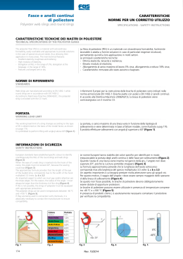
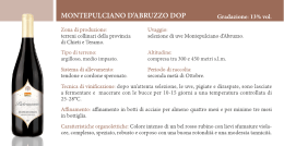
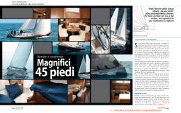
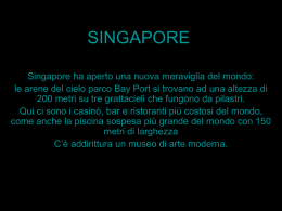
R/SP/8150/03
Data 25/06/2013
SPECIFICA PRODOTTO
ISTRUZIONI PER L’USO E LA MANUTENZIONE
Informazioni tecniche
Condizioni d’uso previste e limiti operativi
Prescrizioni per gli operatori
Rischi residui
Modalità e frequenza delle ispezioni periodiche d’idoneità
BRACA DI SOLLEVAMENTO IN NASTRO PIATTO
IN POLIESTERE UNI EN 1492-1
ART. 8150 – 8153 – 8156 – 8157 – 8158 – 8159 – 8160 – 8161
Sede produttiva Accessori per funi ROBUR
Zona Industriale – C.da S. Nicola
67039 SULMONA (L’AQUILA)
Tel. +39.0864.2504.1 – Fax +39.0864.253132
www.roburitaly.com – [email protected]
Divisione della BETA UTENSILI SPA, Via Volta, 18 - 20845 SOVICO (MB) ITALY Tel. +39.039.20771-Fax + 39.039.2010742
1)
CARATTERISTICHE TECNICHE DELL’ACCESSORIO
MATERIALE IMPIEGATO:
Definizione
Poliestere 100%
Asole:
Le asole sono rinforzate con protezioni antiusura e sono del tipo:
Art. 8150: Asola piatta (Tipo N°1)
Art. 8153: Asola ripiegata ½ larghezza da un lato (Tipo N°3)
Art. 8156, 8157, 8158, 8159, 8160, 8161: Asola ripiegata ½ larghezza da
due lati (Tipo N°4)
Colore:
Il colore della braca identifica in modo immediato il carico massimo di
esercizio WLL (vedi tabella “A”).
Ulteriori segni di identificazione sono rappresentati da righe longitudinali
tante quante sono le tonnellate di portata.
L’articolo è prodotto secondo la norma UNI EN 1492-1 e la sua designazione secondo normativa è
“braca di tipo B2”, ovvero “braca a due strati con rinforzo delle asole”.
Il collaudo viene eseguito in base a specifiche e regole interne in riferimento alla
norma UNI EN ISO 9001.
L’articolo è conforme alla Direttiva Macchine 2006/42/CE.
Divisione della BETA UTENSILI SPA, Via Volta, 18 - 20845 SOVICO (MB) ITALY Tel. +39.039.20771-Fax + 39.039.2010742
CARATTERISTICHE DIMENSIONALI:
TABELLA “A”
Carichi massimi di esercizio (WLL) in funzione del fattore modale
Colore
braca
Viola
Verde
Giallo
Grigio
Rosso
Marrone
Blu
Arancio
H
mm
30
60
90
120
150
180
230
300
Sollevamento Sollevamento a
strozzo
diritto
1t
2t
3t
4t
5t
6t
8t
10 t
0,8 t
1,6 t
2,4 t
3,2 t
4,0 t
4,8 t
6,4 t
8,0 t
braca usata a U
parallela
β=da 0° a 45°
β= da 45° a 60°
2t
4t
6t
8t
10 t
12 t
16 t
20 t
1,4 t
2,8 t
4,2 t
5,6 t
7,0 t
8,4 t
11,2 t
14,0 t
1t
2t
3t
4t
5t
6t
8t
10 t
WLL= CARICO MASSIMO DI ESERCIZIO
COEFFICIENTE DI SICUREZZA: 7
L = LUNGHEZZA DELLA BRACA: DA 1 A 12 METRI.
ATTENZIONE: il coefficiente di sicurezza è soltanto un’indicazione per la sicurezza del prodotto.
Non si devono mai superare i carichi (WLL) indicati nella tabella.
Divisione della BETA UTENSILI SPA, Via Volta, 18 - 20845 SOVICO (MB) ITALY Tel. +39.039.20771-Fax + 39.039.2010742
CODICI DI IDENTIFICAZIONE
VIOLA
CODICE
VERDE
CODICE
GIALLO
CODICE
1 t METRI 1
1 t METRI 2
1 t METRI 2,5
1 t METRI 3
1 t METRI 4
1 t METRI 5
1 t METRI 6
081500010
081500020
081500025
081500030
081500040
081500050
081500060
2 t METRI 1
2 t METRI 1,5
2 t METRI 2
2 t METRI 2,5
2 t METRI 3
2 t METRI 4
2 t METRI 5
2 t METRI 6
2 t METRI 8
081530010
081530015
081530020
081530025
081530030
081530040
081530050
081530060
081530080
3 t METRI 1,5
3 t METRI 2
3 t METRI 2,5
3 t METRI 3
3 t METRI 4
3 t METRI 5
3 t METRI 6
3 t METRI 8
3 t METRI 10
081560015
081560020
081560025
081560030
081560040
081560050
081560060
081560080
081560100
GRIGIO
CODICE
ROSSO
CODICE
MARRONE
CODICE
4 t METRI 2
4 t METRI 3
4 t METRI 4
4 t METRI 5
4 t METRI 6
4 t METRI 8
4 t METRI 10
4 t METRI 12
081570020
081570030
081570040
081570050
081570060
081570080
081570100
081570120
5 t METRI 2
5 t METRI 3
5 t METRI 4
5 t METRI 5
5 t METRI 6
5 t METRI 8
5 t METRI 10
5 t METRI 12
081580020
081580030
081580040
081580050
081580060
081580080
081580100
081580120
6 t METRI 3
6 t METRI 4
6 t METRI 5
6 t METRI 6
6 t METRI 8
6 t METRI 10
081590030
081590040
081590050
081590060
081590080
081590100
BLU
CODICE
ARANCIO
CODICE
8 t METRI 5
8 t METRI 6
8 t METRI 8
8 t METRI 10
081600050
081600060
081600080
081600100
10 t METRI 5
10 t METRI 6
10 t METRI 8
10 t METRI 10
081610050
081610060
081610080
081610100
Nota: la lunghezza effettiva di esercizio (EWL) della braca Robur non differirà più del 3% rispetto alla lunghezza
nominale riportata nelle tabelle precedenti.
Definizioni:
• Carico massimo di esercizio (WLL): la massa che al massimo la braca di nastro tessuto piatto è
progettata per sostenere in tiro dritto, e che una braca è autorizzata a sostenere nel normale
servizio di sollevamento (vedere tabella A).
• Lunghezza nominale (L): lunghezza specifica della braca, da punto portante a punto portante.
• Lunghezza effettiva di esercizio (EWL): lunghezza finita reale della braca, da punto portante a
punto portante.
• Fattore modale: fattore applicato al carico massimo di esercizio (WLL) di una braca di
sollevamento, al fine di arrivare al carico massimo di esercizio per un dato modo di assemblaggio
o utilizzo.
• Coefficiente di sicurezza: è il rapporto tra il carico di rottura minimo garantito e il carico
massimo di esercizio. Nell’articolo in oggetto è 7.
• Ispezione: controllo visivo relativo allo stato della braca per individuare evidenti danneggiamenti
o usure che possono alterarne l’utilizzo.
• Persona competente: persona designata, istruita correttamente, qualificata per conoscenza ed
esperienza pratica, che ha ricevuto le istruzioni necessarie per eseguire le prove e gli esami
richiesti.
2)
SPECIFICHE DI COLLAUDO
L’accessorio è sottoposto presso il costruttore a una serie di severi controlli per accertarne la
funzionalità prestazionale in conformità alla norma UNI EN 1492-1.
Divisione della BETA UTENSILI SPA, Via Volta, 18 - 20845 SOVICO (MB) ITALY Tel. +39.039.20771-Fax + 39.039.2010742
La numerosità dei campioni e i relativi piani di campionamento sono scelti in funzione della
caratteristica da verificare in accordo e per quanto previsto da rigide procedure interne, e i risultati
archiviati nell’ufficio qualità dello stabilimento di Sulmona.
3)
COME LEGGERE LA MARCATURA
All’interno dell’asola, in una posizione protetta, è apposta un’etichetta riportante in maniera
indelebile marcature e sigle che identificano il prodotto e ne definiscono le caratteristiche e
applicazioni.
Parte anteriore
Sul lato anteriore dell’etichetta (fig. 1) sono riportate le
seguenti informazioni:
1)
2)
3)
4)
5)
6)
7)
8)
9)
Materiale 100% PES (poliestere)
Lunghezza nominale
Simbolo del fabbricante
Codice articolo (p. es. 8150)
Codice di rintracciabilità
Data di costruzione
Norma di riferimento (UNI EN 1492-1)
Carico massimo di esercizio a tiro dritto (WLL)
Marchio CE
Fig. 1
Parte posteriore
Sulla parte posteriore (fig. 2) sono riportati le informazioni sul
carico massimo di utilizzazione e il fattore modale da applicare in
funzione della tipologia d’imbraco.
Fig.2
Divisione della BETA UTENSILI SPA, Via Volta, 18 - 20845 SOVICO (MB) ITALY Tel. +39.039.20771-Fax + 39.039.2010742
4)
AVVERTENZE GENERALI
Il manuale deve essere custodito da persona responsabile allo scopo preposta, in un luogo idoneo,
affinché esso risulti sempre disponibile per la consultazione nel miglior stato di conservazione. In
caso di smarrimento o deterioramento, la documentazione dovrà essere prontamente sostituita
scaricandola dal sito del costruttore: www.roburitaly.com
Il costruttore si riserva la proprietà materiale ed intellettuale del presente manuale e ne vieta la
duplicazione, anche parziale, per fini commerciali.
Con riferimento a quanto riportato in queste istruzioni d’uso, BETA UTENSILI SPA declina ogni
responsabilità in caso di:
•
•
•
•
•
•
uso degli accessori contrario alle leggi nazionali sulla sicurezza e sull’antinfortunistica;
errata scelta o predisposizione dell’apparecchio di sollevamento con il quale saranno
connessi;
mancata o errata osservanza delle istruzioni per l’uso;
modifiche agli accessori;
uso improprio e omessa manutenzione ordinaria;
uso combinato ad accessori non conformi.
!ATTENZIONE: I dati di marcatura riportati sull’etichetta applicata alla braca devono essere
sempre perfettamente leggibili; le brache di sollevamento senza riferimenti di identificazione
devono essere rese inutilizzabili e rottamate.
Non è consentito apporre caratteri aggiuntivi a quelli di fabbricazione.
5)
CRITERI DI SCELTA
I parametri che devono essere attentamente considerati nella scelta della braca sono:
5.A CARICO MASSIMO DI ESERCIZIO
Il peso del carico da sollevare deve essere inferiore o uguale al valore del carico massimo di utilizzo
(WLL) previsto per la braca di sollevamento presa in considerazione, in funzione della tipologia di
imbraco, indicato sul prodotto e riportato nella tabella “A”.
Attenzione: l’angolo di ciascun braccio non deve mai superare 60° rispetto alla verticale (fig. 3).
β MAX 60°
Fig. 3
Divisione della BETA UTENSILI SPA, Via Volta, 18 - 20845 SOVICO (MB) ITALY Tel. +39.039.20771-Fax + 39.039.2010742
5.B ELEMENTO DI ACCOPPIAMENTO
Quando si selezionano e specificano le brache di sollevamento, si devono considerare le modalità di
utilizzo e la natura del carico da sollevare.
Se si utilizzano più brache per sollevare il carico, queste devono essere identiche.
Gli eventuali terminali accessori e dispositivi di sollevamento devono essere compatibili con le
caratteristiche delle brache di sollevamento.
Sia il carico che gli eventuali terminali accessori devono essere esenti da bave o asperità che possono
provocare tagli o sfilacciamenti, causando una grave perdita di resistenza.
Assicurarsi che l’elemento di accoppiamento sia adeguato alle caratteristiche di portata della braca,
abbia uno spessore e una composizione chimica adeguati e garantisca una resistenza meccanica
sufficiente alla trazione esercitata dalla presa.
5.C TEMPERATURE D’IMPIEGO
L’intervallo di temperatura in cui è consentito l’impiego della braca di sollevamento in poliestere
(PES) va da –40 °C a +100 °C.
A temperature basse ha luogo la formazione di ghiaccio in presenza di umidità.
Questo può agire da agente di taglio e abrasivo, causando danni interni alla braca. Inoltre il ghiaccio
riduce la flessibilità della braca, rendendola in casi estremi inservibile per l’utilizzo.
6) CARICHI NON AMMESSI
Non è consentita la movimentazione dei seguenti carichi:
•
•
•
•
•
aventi un peso superiore al carico massimo di utilizzazione;
aventi temperature superiori o inferiori a quelle ammesse;
classificati come pericolosi (p. es. materiali infiammabili, esplosivi ecc.);
che possono cambiare la loro configurazione statica e/o il loro baricentro o il loro stato
chimicofisico;
immersi in soluzioni acide o esposti a vapori acidi; a tal proposito, la tabella
successiva elenca, per una maggior comprensione, la resistenza del poliestere agli
agenti chimici:
TABELLA DI RESISTENZA AGLI AGENTI CHIMICI
Materiale braca Acidi Alcoli Aldeidi Alcali forti Sbiancanti Solventi Idrocarburi Petroli Detergenti Acqua di mare
Poliestere
*
si
no
no
si
* Il poliestere si disintegra in acido solforico concentrato
si
si
si
si
si
Divisione della BETA UTENSILI SPA, Via Volta, 18 - 20845 SOVICO (MB) ITALY Tel. +39.039.20771-Fax + 39.039.2010742
7) CONTROLLI PRELIMINARI
Prima di ogni utilizzo, le brache di sollevamento devono essere controllate da personale competente
adeguatamente addestrato.
• La braca deve essere ispezionata per assicurare che non siano presenti difetti, tagli,
sfilacciamenti o danni, inclusi danni nascosti dalla sporcizia, i quali possono
influire sul sicuro utilizzo dell’accessorio.
• Controllare l’integrità della marcatura in tutte le sue parti, in particolare le
prescrizioni di portata, al fine di identificare con precisione l’accessorio in
funzione del carico di lavoro.
• Controllare le cuciture, i rinforzi e le eventuali protezioni sui punti di contatto o
presa.
8) INSTALLAZIONE - ISTRUZIONI PER IL MONTAGGIO
Quando si utilizzano le brache di sollevamento, devono essere eseguite corrette pratiche di
imbracatura. Sollevamento e abbassamento devono essere pianificati prima di cominciare la
movimentazione.
Le brache di sollevamento devono essere posizionate sul carico correttamente e in modo sicuro.
Devono essere collocate sul carico in maniera che il peso gravi uniformemente su tutta la loro
larghezza; non devono quindi essere mai annodate o torte.
Le brache devono essere protette contro i bordi taglienti, l’attrito e l’abrasione, causati sia dal carico
che dal’apparecchiatura di sollevamento. Dove rinforzi e protezioni sono parte integrante della braca,
essi devono essere correttamente posizionati. Nel caso in cui questi, anche se correttamente
posizionati, non siano sufficienti, devono essere integrati con protezioni aggiuntive.
Le brache devono essere protette da sorgenti di calore e fiamme libere.
All’interno dell’asola non devono essere inseriti attrezzi che abbiano spigoli taglienti o bave, e
l’angolo di apertura della stessa non deve superare i 20° (fig. 4), per evitare che la cucitura possa
strapparsi sotto carico.
CORRETTO
ERRATO
Fig. 4
Divisione della BETA UTENSILI SPA, Via Volta, 18 - 20845 SOVICO (MB) ITALY Tel. +39.039.20771-Fax + 39.039.2010742
Il raggio di curvatura del gancio che accoglie l’asola della braca deve essere almeno 0,75 volte la
larghezza portante della braca.
Nella fig. 5, l’illustrazione di due esempi di inserimento dell’asola nel gancio: uno corretto, con
l’asola ben distesa nella sella del gancio adeguato; e l’altro errato, con l’asola aggrovigliata nella sella
di un gancio di raggio troppo piccolo.
CORRETTO
ERRATO
Fig. 5
Le cuciture delle brache non devono mai essere collocate sui ganci o su altri dispositivi di
sollevamento. Durante il sollevamento le cuciture devono lavorare sempre sulla parte dritta della
braca.
Il carico deve essere fissato dalla braca in maniera tale da non potersi rovesciare durante il
sollevamento. La braca deve essere disposta in modo che il punto di sollevamento sia direttamente
sopra al baricentro e il carico sia bilanciato e stabile. In mancanza di queste condizioni, la braca
potrebbe muoversi e generare calore a causa dell’attrito.
Quando si usa una braca a “U”, il carico deve essere fissato e stabile, in quanto non vi è azione di
presa come con il sistema a strozzo, e la braca può rotolare attraverso il punto di sollevamento.
Per le brache utilizzate a coppie, è raccomandato l’utilizzo di un bilanciere, cosicché i bracci della
braca siano sospesi quanto più verticalmente possibile e per assicurare che il carico sia equamente
diviso tra i bracci.
Divisione della BETA UTENSILI SPA, Via Volta, 18 - 20845 SOVICO (MB) ITALY Tel. +39.039.20771-Fax + 39.039.2010742
Quando una braca è utilizzata a strozzo, deve essere posizionata in modo da consentire che si formi
l’angolo naturale di 120° ed evitare la generazione di calore per attrito.
La braca di sollevamento non deve mai essere forzata in posizione, né si deve tentare di stringere la
presa. Nella fig. 6 è illustrato il metodo corretto di fissaggio di un carico in una braca di sollevamento
usata a doppio strozzo. Il doppio strozzo offre una maggiore sicurezza e contribuisce a impedire che
il carico scivoli attraverso la braca.
Fig. 6
Nel caso di brache utilizzate come sistemi a tre bracci, se i bracci non sono simmetricamente disposti
nel piano, vi sarà una tensione più grande nel braccio in cui la somma degli angoli piani rispetto ai
bracci adiacenti è più elevata. Si ha il medesimo risultato nelle brache a quattro bracci, con
l’eccezione che occorrerebbe mettere in conto anche la rigidità del carico; se il carico è rigido, può
avvenire che la maggioranza della massa sia sopportata solamente da tre o anche due bracci, mentre i
rimanenti bracci servono solo a equilibrare il carico.
9)
USO DELL’ACCESSORIO - PRESA E MANOVRA
Prestare sempre la massima attenzione a ogni specifico avvertimento per la movimentazione del
carico. Prima di azionare il sollevatore, assicurarsi che il carico sia libero di muoversi e non sia
bloccato da elementi di collegamento o da altri impedimenti.
È buona norma, prima di procedere al sollevamento, effettuarne uno di prova, per testare l’insieme.
Mettere in tiro la braca prima di sollevare.
Stare lontani con le mani o altre parti del corpo quando la braca è posta in tensione.
Il carico va sollevato lentamente; va controllato che sia sicuro e che assuma la posizione preventivata.
Muovere il carico con movimenti lenti, lineari e costanti, evitando brusche accelerate o frenate che,
per effetto dell’inerzia, possono creare pericolose oscillazioni.
Predisporre anticipatamente il luogo di deposito al suolo del carico, assicurandosi che il terreno (o il
pavimento) sia adeguatamente resistente per sopportare il carico.
Assicurarsi che l’accesso al luogo di deposito sia privo di ostacoli e che le persone siano a distanza di
sicurezza.
Il carico deve essere appoggiato con cautela, facendo attenzione che la braca non si impigli; non
intrappolare quindi la braca sotto il carico al momento della posa a pavimento.
Prima di allentare la braca, controllare che il carico sia ben sopportato e stabile.
Una volta che il carico è appoggiato in sicurezza, la braca deve essere rimossa a mano, e mai
allontanata con l’apparecchio di sollevamento, né trascinata sul pavimento.
Divisione della BETA UTENSILI SPA, Via Volta, 18 - 20845 SOVICO (MB) ITALY Tel. +39.039.20771-Fax + 39.039.2010742
10)
CONTROINDICAZIONI D’USO
L’utilizzo delle brache di sollevamento per scopi non previsti, il loro uso in condizioni estremamente
pericolose e la carenza di manutenzione possono comportare gravi situazioni di pericolo per
l’incolumità delle persone esposte e di danno per l’ambiente di lavoro, oltre che pregiudicare la
funzionalità e la sicurezza effettiva del prodotto. Le azioni di seguito citate, che, ovviamente, non
possono coprire l’intero arco di potenziali possibilità di “cattivo uso” dell’accessorio, costituiscono
tuttavia quelle “ragionevolmente” più prevedibili. Quindi:
•
•
•
•
•
•
•
•
•
•
•
•
•
•
•
NON utilizzare la brache collegandole ad apparecchiature di dimensioni, temperatura,
punto d’aggancio e forma non idonei alle sue caratteristiche;
NON applicare carichi maggiori alla portata della braca;
NON utilizzare le brache in poliestere per sollevare carichi con spigoli o punte;
NON utilizzare brache di dubbia provenienza e/o identificazione;
NON tentare di effettuare ricuciture o riparazioni sulle brache;
NON sollevare il carico sottoponendo le brache a sollecitazioni di tipo dinamico;
NON fare oscillare il carico durante la movimentazione;
NON sollevare e trasportare carichi in volo (aeromobili);
NON usare le brache per trazionare carichi vincolati;
NON mettere in tensione apparecchiature che possono cambiare la loro configurazione
statica, il loro baricentro o lo stato chimicofisico;
NON utilizzare l’accessorio in apparecchiature destinate al trasporto di persone o
animali;
NON allacciare le brache tra di loro con dei nodi per ottenere prolunghe;
NON accorciare mai le brache facendo nodi; la resistenza potrebbe diminuire del 50%;
NON utilizzare le brache immerse in soluzioni acide o in ambienti con vapori acidi;
NON lasciare le brache sul terreno, al fine di evitare che possano transitarvi sopra ruote
o cingoli di veicoli.
11)
IDONEITÀ ALL’UTILIZZO
L’accessorio è stato sottoposto a collaudo presso il costruttore per accertare la rispondenza funzionale
e prestazionale dello stesso. L’attestato che accompagna la fornitura certifica il superamento con esito
positivo dei test di collaudo previsti dalla norma. L’utilizzatore deve eseguire in ogni caso, prima di
iniziare a operare, la verifica della rispondenza funzionale e prestazionale dell’accessorio installato
per confermare l’idoneità all’impiego dell’intera installazione.
Divisione della BETA UTENSILI SPA, Via Volta, 18 - 20845 SOVICO (MB) ITALY Tel. +39.039.20771-Fax + 39.039.2010742
12)
ISPEZIONE E MANUTENZIONE
Comprende gli interventi di ispezione e manutenzione, eseguiti da persona competente istruita allo
scopo, relativi a controlli durante l’impiego ed eventuali azioni, come previsto nella tabella
“Interventi di manutenzione e controllo”.
Al termine dell’operazione di sollevamento le brache devono essere riportate alle corrette condizioni
di stoccaggio. Devono essere conservate in condizioni pulite e asciutte, in locali ben ventilati e a
temperatura ambiente, al riparo da fonti di calore, non a contatto con sostanze chimiche, fumi,
superfici corrosive, luce solare diretta o altre sorgenti di radiazioni ultraviolette.
Prima di essere immagazzinate, le brache devono essere ispezionate, per controllare eventuali danni
verificatisi durante l’utilizzo. Verificare l’assenza, su tutta la loro lunghezza, di difetti superficiali
quali tagli, incisioni, sfilacciamenti o abrasioni. Controllare l’integrità e la leggibilità della marcatura
posta sull’etichetta e l’identificazione della braca. Le brache che presentano difetti, anche lievi, non
devono essere immagazzinate, ma rottamate e sostituite.
Se le brache di sollevamento sono venute a contatto con acidi e/o alcali prima
dell’immagazzinamento, si raccomanda la diluzione in acqua o la neutralizzazione con un mezzo
idoneo.
Le brache bagnate durante l’utilizzo o in seguito a un lavaggio devono essere appese e lasciate
asciugare naturalmente prima di essere conservate.
Qui di seguito è riportata la tabella che riassume le operazioni di manutenzione da eseguire e la loro
frequenza.
Tabella interventi di manutenzione e controllo
Tipo di controllo
Controllo visivo gener.
Controllo etichetta
Usura
Frequenza intervento
A ogni utilizzo
Mese
Anno
x
x
x
La braca che ha perso le sue caratteristiche e, di conseguenza, l’attitudine all’impiego per cui è
stata costruita deve essere tagliata e demolita, in modo tale che non possa più essere utilizzata.
13)
DEMOLIZIONE E ROTTAMAZIONE DELL’ACCESSORIO
L’accessorio deve essere demolito mediante taglio, in modo tale che non possa più essere utilizzato,
nel caso presenti:
- difetti superficiali quali tagli, incisioni, sfilacciamenti o abrasioni;
- etichetta mancante, abrasa o illeggibile in modo tale da renderne difficile l’individuazione.
Divisione della BETA UTENSILI SPA, Via Volta, 18 - 20845 SOVICO (MB) ITALY Tel. +39.039.20771-Fax + 39.039.2010742
R/SP/8150/03
Date 25/06/2013
PRODUCT SPECIFICATIONS
OPERATING AND MAINTENANCE INSTRUCTIONS
Technical Specifications
Operating Conditions and Limits
Operator’s Instructions
Residual Risks
How and how often periodical fitness inspections should be conducted
WEBSLINGS,
MADE OF POLYESTER, UNI EN 1492-1
ITEMS 8150 – 8153 – 8156 – 8157 – 8158 – 8159 – 8160– 8161
Manufacturing site ROBUR wire rope accessories
Zona Industriale – C.da S. Nicola
I-67039 SULMONA (L’AQUILA)
Tel. +39.(0)864.2504.1 – Fax +39.(0)864.253132
www.roburitaly.com – [email protected]
Division of BETA UTENSILI SPA, Via Volta, 18 - 20845 SOVICO (MB) ITALY Tel. +39.(0)39.20771-Fax + 39.(0)39.2010742
1)
MATERIAL:
Definition
Loop reinforcement:
Colour
TECHNICAL SPECIFICATIONS OF ACCESSORY
100% polyester
Reinforced loops with antiwear protection, eye types:
Art.8150: Flat Eye (type N°1)
Art.8153: Folded Eye ½ width from one side (type N°3)
Art.8156-8157-8158-8159-8160-8161: Folded Eye ½ width from two
sides (type N°4)
Sling colour immediately identifies working load limit (WLL)
(see Table “A”)
The number of lines along the length of the websling indicates its load
capacity in tons.
The item is manufactured in accordance with UNI EN 1492-1. Its description under this stardard is
“B2 type slings”, “two layer sling with reinforced eyes”.
The test is performed on the basis of in-house specifications and rules in accordance with UNI EN
ISO 9001.
The item complies with Machine Directive 2006/42/EEC.
Division of BETA UTENSILI SPA, Via Volta, 18 - 20845 SOVICO (MB) ITALY Tel. +39.(0)39.20771-Fax + 39.(0)39.2010742
DIMENSIONAL SPECIFICATIONS:
TABLE “A”
Working load limits (WLL) according to modal factor
Sling
colour
Purple
Green
Yellow
Grey
Red
Brown
Blue
Orange
Straight
H
mm lifting
30
60
90
120
150
180
230
300
1t
2t
3t
4t
5t
6t
8t
10 t
Choke hitch
0.8 t
1.6 t
2.4 t
3.2 t
4.0 t
4,8 t
6,4 t
8,0 t
U-shaped sling
parallel
β= 0° ÷ 45°
β= 45° ÷ 60°
2t
4t
6t
8t
10 t
12 t
16 t
20 t
1.4 t
2.8 t
4.2 t
5.6 t
7.0 t
8,4 t
11,2 t
14,0 t
1t
2t
3t
4t
5t
6t
8t
10 t
WLL= WORKING LOAD LIMIT
SAFETY COEFFICIENT: 7
L = SLING LENGTH: 1 TO 12 METRES.
CAUTION:
The safety coefficient is only provided by way of example, in relation to product
safety.
The working load limits (WLL) shown in the table should never be exceeded.
Division of BETA UTENSILI SPA, Via Volta, 18 - 20845 SOVICO (MB) ITALY Tel. +39.(0)39.20771-Fax + 39.(0)39.2010742
IDENTIFICATION CODES
PURPLE
CODE
GREEN
CODE
YELLOW
CODE
1 t METRES 1
1 t METRES 2
1 t METRES 2,5
1 t METRES 3
1 t METRES 4
1 t METRES 5
1 t METRES 6
081500010
081500020
081500025
081500030
081500040
081500050
081500060
2 t METRES 1
2 t METRES 1,5
2 t METRES 2
2 t METRES 2,5
2 t METRES 3
2 t METRES 4
2 t METRES 5
2 t METRES 6
2 t METRES 8
081530010
081530015
081530020
081530025
081530030
081530040
081530050
081530060
081530080
3 t METRES 1,5
3 t METRES 2
3 t METRES 2,5
3 t METRES 3
3 t METRES 4
3 t METRES 5
3 t METRES 6
3 t METRES 8
3 t METRES 10
081560015
081560020
081560025
081560030
081560040
081560050
081560060
081560080
081560100
GREY
CODE
RED
CODE
BROWN
CODE
4 t METRES 2
4 t METRES 3
4 t METRES 4
4 t METRES 5
4 t METRES 6
4 t METRES 8
4 t METRES 10
4 t METRES 12
081570020
081570030
081570040
081570050
081570060
081570080
081570100
081570120
5 t METRES 2
5 t METRES 3
5 t METRES 4
5 t METRES 5
5 t METRES 6
5 t METRES 8
5 t METRES 10
5 t METRES 12
081580020
081580030
081580040
081580050
081580060
081580080
081580100
081580120
6 t METRES 3
6 t METRES 4
6 t METRES 5
6 t METRES 6
6 t METRES 8
6 t METRES 10
081590030
081590040
081590050
081590060
081590080
081590100
BLUE
CODE
ORANGE
CODE
8 t METRES 5
8 t METRES 6
8 t METRES 8
8 t METRES 10
081600050
081600060
081600080
081600100
10 t METRES 5
10 t METRES 6
10 t METRES 8
10 t METRES 10
081610050
081610060
081610080
081610100
Note: the effective working length (EWL) of a Robur sling will not differ more than 3% of the nominal length indicated in
the previous tables.
Definitions:
• Working load limit (WLL): the maximum load a websling has been designed to support when
pulled straight and a sling is allowed to support during ordinary lifting operations (see Table A).
• Nominal length (L): specific length of the sling, from bearing point to bearing point.
• Effective working length (EWL): actual length of the sling from bearing point to bearing point.
• Modal factor: factor applied to the working load limit (WLL) of a websling to get to the
maximum working load for a certain assembly or operation mode.
• Safety coefficient: guaranteed minimum breaking load to working load limit ratio. In this item it
is 7.
• Inspection: visual testing of the state of the websling, to check for clear damage or wear which
may affect its use.
• Trained person: a designated, suitably trained person who has proper know-how and practical
expertise and has been given the instructions needed to perform any required tests and
examinations.
2)
TESTING SPECIFICATIONS
The accessory is subjected to several stringent tests for performance and compliance with UNI EN
1492-1 at the manufacturer’s.
Division of BETA UTENSILI SPA, Via Volta, 18 - 20845 SOVICO (MB) ITALY Tel. +39.(0)39.20771-Fax + 39.(0)39.2010742
The number of samples and the related sampling plans are chosen according to the characteristic to
test under stringent internal procedures, and the results are filed in the quality department of the
factory in Sulmona.
3)
HOW TO READ MARKINGS
The loop accommodates – in a protected position – a label with indelible marks and codes which
identify the product and define its specifications and applications.
Front
The front side of the label (fig. 1) carries the following
information:
1)
2)
3)
4)
5)
6)
7)
8)
9)
100% PES (polyester) material
Nominal length
Manufacturer’s symbol
Item code (e.g. 8150)
Traceability code
Manufacturing date
Reference standard (UNI EN 1492-1)
Working load limit (WLL) when pulled straight
CE mark
Fig. 1
Back
The back side (fig. 2) carries information about the maximum
operating load and the modal factor to apply according to sling
type.
Fig. 2
Division of BETA UTENSILI SPA, Via Volta, 18 - 20845 SOVICO (MB) ITALY Tel. +39.(0)39.20771-Fax + 39.(0)39.2010742
4)
GENERAL WARNINGS
The manual must be kept by the person in charge in a suitable place and readily available for
consultation, in optimal conditions. should it be lost or damaged, the manual can easily be retrieved
on the constructor's web site: www.roburitaly.com
the constructor detains all material and intellectual rights on the manual, and restricts its duplication,
albeit partial, for any commercial use.
As regards the information provided in these operating instructions, BETA UTENSILI SPA will
accept no responsibility in the event of:
•
•
•
•
•
•
any use of the accessories other than the uses under national safety and accident
prevention laws;
mistaken choice or arrangement of the apparatus they are going to be connected to;
failure to comply with, or properly follow, the operating instructions;
changes to the accessories;
misuse or failure to carry out routine maintenance jobs;
use with noncompliant accessories.
!CAUTION: The marking data on the label attached to the websling should always be
perfectly legible; any webslings that do not carry any identification references should be made
unusable and scrapped.
No characters other than the manufacturer’s may be affixed.
5)
SELECTION CRITERIA
The following parameters should be carefully considered in choosing the websling:
5.A WORKING LOAD LIMIT
The weight of the load to lift should be lower than or equal to the working load limit (WLL)
recommended for the websling being considered, according to sling type, as printed on the product
and shown in Table “A”.
Caution: the angle of each arm should never exceed 60° compared to the vertical (fig. 3).
β MAX 60°
Fig. 3
Division of BETA UTENSILI SPA, Via Volta, 18 - 20845 SOVICO (MB) ITALY Tel. +39.(0)39.20771-Fax + 39.(0)39.2010742
5.B
CONNECTING PART
When any websling is selected and specified, both the purpose and the type of load to lift should be
considered.
If several slings are used to lift the load, these should be identical.
Any additional terminals and lifting devices should be compatible with the characteristics of the
webslings.
Both the load and any additional terminals should be free from fins or roughness which might cause
cuts or breaks, thereby resulting in major strength loss.
Make sure that the connecting part suits the load capacity of the sling, is thick enough, has a proper
chemical composition and an adequate mechanical resistance to traction forces.
5.C OPERATING TEMPERATURES
The temperature range within which the polyester (PES) websling can be used is –40 °C ÷ +100 °C.
At low temperatures ice will form in the presence of humidity.
This may result in cuts and abrasion, thereby causing internal damage to the sling. In addition, ice
will affect the flexibility of the sling, thereby making it unserviceable under extreme circumstances.
6) NONPERMISSIBLE LOADS
The following loads should not be handled:
•
•
•
•
•
any load exceeding the working load limit in weight;
any load whose temperature does not lie within the permissible range;
any load classified as hazardous (e.g. flammable, explosive materials etc.);
any load that may change its static configuration and/or centre of gravity or chemical
and physical state;
any load immersed in acid solutions or exposed to acid vapours; the table below deals
with polyester resistance to chemicals:
TABLE: RESISTANCE TO CHEMICALS
Sling material Acids Alcohols Aldehydes Strong alkalis Bleachers Solvents Hydrocarbons Oils Detergents Sea water
Polyester
*
yes
no
no
yes
* Polyester disintegrates in concentrated sulphuric acid
yes
yes
yes
yes
yes
Division of BETA UTENSILI SPA, Via Volta, 18 - 20845 SOVICO (MB) ITALY Tel. +39.(0)39.20771-Fax + 39.(0)39.2010742
7) PRELIMINARY TESTS
Before any websling is used, it should be tested by suitably trained personnel.
• The sling should be inspected to make sure that it is free from defects, cuts, breaks
or damage, including damage hidden by dirt, which might affect the safety of the
accessory.
• Check the state of all the parts of the marking; in particular make sure that the
capacity requirements are met, so that the accessory can be accurately identified
according to the working load.
• Check the stitches as well as the reinforcements and any protective parts on the
contact or grip points.
8) INSTALLATION - ASSEMBLY INSTRUCTIONS
Whenever any websling is used, proper slinging procedures should be followed. Lifting and lowering
operations should be planned before handling.
The webslings should be safely secured to the load.
They should be so placed on the load as to allow weight to be uniformly distributed over their entire
width; hence they should never be knotted or twisted.
The slings should be protected against sharp edges, friction and abrasion, as caused by both the load
and the lifting device. Any reinforcements and protective parts that are an integral part of the sling
should be correctly placed. If these should not prove enough, even if correctly placed, they should be
supplemented with additional protective parts.
The slings should be protected from heat sources and open flames.
The loop should not accommodate any devices with sharp edges or fins, and its opening angle should
not exceed 20° (fig. 4), to prevent the stitches from getting torn under any loads.
CORRECT
INCORRECT
Fig. 4
Division of BETA UTENSILI SPA, Via Volta, 18 - 20845 SOVICO (MB) ITALY Tel. +39.(0)39.20771-Fax + 39.(0)39.2010742
The radius of curvature of the hook accommodating the sling loop should be at least 0.75 times the
load-bearing width of the sling.
Fig. 5 shows two examples of loop insertion into the hook, namely a correct one, with the loop
stretched out in the saddle of a suitable hook, and an incorrect one, with the loop tangled in the saddle
of a hook with an excessively small radius.
CORRECT
INCORRECT
Fig. 5
The stitches of the slings should never be placed on the hooks or on any other lifting devices. While
lifting any load, the stitches should always work on the straight part of the sling.
The load should be so secured by the sling as not to overturn while being lifted. The sling should be
so placed that the lifting point lies just above the centre of gravity and the load is balanced and firm.
If these conditions are not satisfied, the sling might move and produce heat through friction.
Whenever a U-shaped sling is used, the load should be well secured and firm, because there is no
grip, unlike the choke hitch system, and the sling may roll through the lifting point.
As for slings used in pairs, it is recommended that a rocker arm be used, so that the arms of the sling
can be suspended as vertically as possible and the load can be equally distributed between the arms.
Division of BETA UTENSILI SPA, Via Volta, 18 - 20845 SOVICO (MB) ITALY Tel. +39.(0)39.20771-Fax + 39.(0)39.2010742
When the sling is used with a choke hitch, it should be so positioned as to form a natural angle of
120° and avoid producing heat through friction.
The websling should never be forced into position, nor should hold be increased. Fig. 6 shows how to
correctly secure a load in a websling used with a double choke hitch, which results in enhanced safety
and helps prevent the load from sliding through the sling.
Fig. 6
Whenever any slings are used as three-arm systems, if the arms are not symmetrically arranged in the
plane, tension will be higher in the arm with the largest sum of the plane angles compared to the
adjacent arms. The same result is achieved in four-arm slings; only the rigidity of the load should also
be considered. If the load is rigid, mass may mainly be supported by three or even two arms, the
remaining arms just performing a load balancing function.
9)
USING ACCESSORY – GRIP AND HANDLING
Always pay attention to any specific warning when handling the load. Before operating the lifting
apparatus, make sure that the load is capable of freely moving and is not stopped by any connecting
parts or any other obstacles.
Before lifting any load, it is recommended that a test lift be carried out.
Pull the sling before lifting the load.
Keep your hands or any other parts of your body away if the sling has been pulled.
The load should be lifted slowly, making sure that it has been fixed firmly and takes the expected
position.
Move the load slowly, linearly and continuously, avoiding sudden acceleration or braking, which may
cause – through inertia – dangerous swinging.
Choose the place where to put down the load onto the ground beforehand, making sure that the
ground (or the floor) is capable of supporting the load.
Make sure that the place where the load is to be put down is free from obstacles and that everybody is
safely distant from it.
The load should be put down cautiously, being careful not to get the sling entangled; hence do not let
the sling be trapped under the load, while laying it on the floor.
Before loosening the sling, make sure that the load is suitably supported and firm.
Once the load has been put down safely, the sling should be removed by hand and should never be
moved away with the lifting apparatus, nor should it be dragged on the floor.
Division of BETA UTENSILI SPA, Via Volta, 18 - 20845 SOVICO (MB) ITALY Tel. +39.(0)39.20771-Fax + 39.(0)39.2010742
10)
NONPERMISSIBLE USE
Using the webslings for any purposes other than the purposes they have been designed for, using
them under extremely dangerous conditions and performing poor maintenance may pose a severe
hazard to the safety of the people being exposed and cause severe damage to the working
environment, while affecting the actual serviceability and safety of the product. The precautions
mentioned below, which, obviously enough, cannot cover the whole spectrum of potential “misuses”
of the accessory, should be “reasonably” deemed to be the most common steps to take. Therefore:
•
•
•
•
•
•
•
•
•
•
•
•
•
•
•
DO NOT connect the slings to any apparatus which does not match their specifications
in terms of size, temperature, hook-up point and shape;
DO NOT apply loads exceeding the carrying capacity of the sling;
DO NOT use polyester slings to lift edged or pointed loads;
DO NOT use unreliable and/or poorly identified slings;
DO NOT attempt to restitch or mend any slings;
DO NOT lift the load while subjecting the slings to dynamic stress;
DO NOT let the load swing while handling it;
DO NOT lift and carry any loads in any aircraft;
DO NOT use the slings to pull restrained loads;
DO NOT stretch any apparatus that may change its static configuration, centre of
gravity or chemical and physical state;
DO NOT use the accessory in any apparatus designed to carry people or animals;
DO NOT connect the slings to each other through knots to extend them;
DO NOT shorten the slings through knots; a 50% reduction in strength might occur;
DO NOT use any slings immersed in acid solutions or in the presence of acid vapours;
DO NOT leave the slings on the ground, to prevent any vehicle wheels or tracks from
running on them.
11)
FITNESS FOR USE
The accessory was tested for serviceability and performance at the manufacturer’s. The certificate
supplied with it states that the tests under the relevant standards were passed. However, before
starting working, the user should test the installed accessory for serviceability and performance, to
prove the entire system is fit for use.
Division of BETA UTENSILI SPA, Via Volta, 18 - 20845 SOVICO (MB) ITALY Tel. +39.(0)39.20771-Fax + 39.(0)39.2010742
12)
INSPECTION AND MAINTENANCE
Inspections and maintenance jobs should be performed by a trained person, who should check the
accessory during use and take such steps as may be required according to the table “Maintenance
jobs and inspections”.
After any load has been lifted, the slings should be restored to proper storage conditions. They should
be stored under clean and dry conditions, in well-ventilated rooms, at ambient temperature, away
from heat sources, and not in contact with chemicals, fumes, corrosive surfaces, direct sunlight or any
other ultraviolet radiation sources.
Before being stored away, the slings should be checked for any damage caused during operation.
Check the slings for such surface defects as cuts, indentations, breaks or abrasions over their entire
length. Check the markings on the label and the identification information about the slings and make
sure that they are legible. Any slings with defects – including small defects – should be scrapped and
replaced, and should not be stored away.
If the webslings have come into contact with any acids and/or alkalis before being stored away,
dilution with water or neutralization with a suitable medium is recommended.
Any slings that get wet while being used or after being washed should be hung and left to dry
naturally before being stored away.
The table below sums up the maintenance jobs to carry out and their frequency.
Maintenance jobs and inspections
Type of inspection
General visual inspection
Label state
Wear
Frequency
Whenever used
Month
Year
x
x
x
Any sling that has lost its characteristics and is thus no longer fit for the purpose it has been
designed for should be cut and scrapped, so that it cannot be used anymore.
13)
SCRAPPING ACCESSORY
The accessory should be scrapped by cutting, so that it can no longer be used, if:
- it has any surface defects, including cuts, indentations, breaks and abrasion;
- the label is missing, worn or illegible to such an extent as to be hardly identifiable.
Division of BETA UTENSILI SPA, Via Volta, 18 - 20845 SOVICO (MB) ITALY Tel. +39.(0)39.20771-Fax + 39.(0)39.2010742
Scaricare