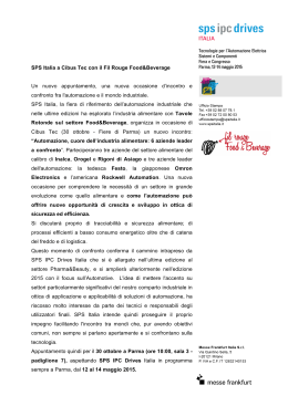
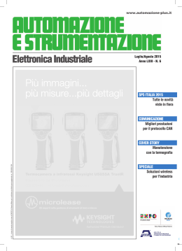
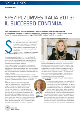
Deutsch
Français
PAW Mischer-Stellmotor Typ SR5/SR10
SR5 / SR10
PAW Mischer-Stellmotor
Servomoteur de vanne PAW
Valve actuator PAW
Servomotore di valvole PAW
Verwendung
Die PAW Mischer-Stellmotore Typ SR5 und SR10 werden als elektromotorische Antriebe für PAW Mischer (3- und 4-Wege-Mischer, Nennweiten DN20
bis DN50) eingesetzt. Die Stellmotore sind für die Ansteuerung durch handelsübliche Regelsysteme mit 3-Punkt Ausgang vorgesehen.
Wirkungsweise
Der PAW Mischer-Stellmotor Typ SR5 bzw. SR10 wird infolge einer patenten
Rasttechnik einfach auf den Mischer aufgesteckt. Die Befestigung erfolgt
mittels zweier Rastbolzen, die zum Lieferumfang gehören. Diese beiden
Rastbolzen dienen zusätzlich als Verdrehsicherung. Aufgrund der kompakten
Bauform und geringen Abmessungen passen die Stellmotore SR5 und SR10
in die Ausschnitte der Isolationen aller PAW Heizungs-Armaturengruppen.
Der Drehwinkel (Stellbereich) ist durch Endschalter auf 90° begrenzt. Das
Erreichen der Endschalter führt zum Abschalten des Antriebes; der Antrieb ist
dann stromlos.
Der Stellmotor kann mit Hilfe eines Stellknopfes (Betätigung mit SchlitzSchraubendreher) auf Handbetrieb umgeschaltet werden. Dabei wird das
Getriebe ausgerastet und der Mischer kann mit dem Hand-Drehgriff
(Stellungsanzeiger) beliebig eingestellt werden.
Hinter / unter dem Hand-Drehgriff ist eine blau-rote Farbskala zur Anzeige der
Mischerstellung eingelegt. Im Lieferzustand befindet sich der Stellantrieb am
linken Endanschlag. Die Skala ist für den Einsatzfall “Vorlauf rechts“
vorbereitet (im Sichtfenster des Hand-Drehgriffs ist die Skala blau). Für den
Einsatzfall “Vorlauf links“ kann die Farbskala umgekehrt werden, so dass
dann die Skala im Sichtfenster des Hand-Drehgriffs rot ist – siehe 3) der
Montageanleitung (Rückseite).
Anschluss-Schema Dreipunkt-Steuerung
br
blau Regler
weiß
English
Valve actuator type SR5/SR10
Servomotore PAW Tipo SR5/SR10
Application
Le servomoteur de vanne PAW type SR5 et SR10 est utilisé pour la motorisation
de vannes mélangeuses PAW (3 voies et 4 voies, DN 20 à DN50). La commande
se fait par des systèmes de régulation 3-points usuels.
Application
The valve actuators PAW type SR5 and SR10 can be used for motorising PAW
slipper valves (3 way and 4 way valves, DN20 up to DN50). These actuators can
be operated by any controller/compensator with a 3-point output.
Uso
Il servomotore PAW tipo SR5 e SR10 viene impiegato per la motorizzazione di
miscelatori PAW (miscelatore a 3 – 4 vie, DN20 – DN40). La messa in funzione
avviene attraverso un comune sistema di regolazione a tre punti.
Mode de fonctionnement
Le servomoteur de vanne PAW type SR5 resp. SR10 est monté sur la vanne
mélangeuse simplement en l’enqliquetant grâce à son système de montage
pratique. La fixation se fait au moyen de deux tiges de guidage fournies avec
l'appareil . Ces tiges servent également d'arrêt anti-rotation. Par ses formes
compactes et ses petites tailles, les servomoteurs SR5 et SR10 s’adaptent
parfaitement à la découpe des coffrets d'isolation de tous les groupes
hydrauliques PAW prévus à cet effet.
L'angle de rotation est limité à 90° par des contacts de fin de course. Lorsque
ceux-ci sont atteints, le servomoteur est coupé électriquement, c.à.d. il ne
consomme plus de courant.
Le servomoteur peut être mis en fonctionnement manuel au moyen d'un bouton
sur le boîtier. En tournant ce bouton, le réducteur est débrayé et la vanne
mélangeuse peut ainsi être mise dans n'importe quelle position en tournant la
poignée du servomoteur. La position de la vanne mélangeuse est indiquée sur le
cadran bleu-rouge réversible. Le servomoteur est livré en position finale à
gauche pour être utilisé pour «départ à droite» Ainsi, la partie bleue du cadran
est visible. Pour l’utilisation «départ à gauche», le cadran peut être tourné pour
que la partie rouge du cadran soit présentée dans la découpe de la poignée (voir
fig 3 de l’instruction de montage au verso).
Operation
Modalità di funzionamento
Grazie ad un pratico sistema ad innesto il servomotore PAW tipo SR5 e SR10
viene inserito con facilità sul miscelatore. Il fissaggio avviene grazie a due viti
ad innesto, incluse nella fornitura, che hanno anche la funzione di elementi
anti-rotazione.
I servomtori SR5 e SR10 si adattano perfettamente alla sezione dell’isolamento
di tutti i gruppi idraulici PAW grazie alla loro forma compatta e alle ridotte
dimensioni d’ingombro.
L’angolo di rotazione è limitato a 90° dagli interrutori di fine corsa; quando
questi si spengono s’interrompe l’alimentazione elettrica del servomotore, che
quindi non consuma corrente elettrica.
Il servomotore può essere messo in funzione manualmente ruotando con un
cacciaviti ad intaglio un interruttore. In questo modo vengono disinnestati gli
igranaggi e il miscelatore può essere posizionato in qualsiasi posizione
ruotando la manopola del servomotore. Tale posizione è indicata da una scala
di colori blu-rosso, situata dietro/sotto la manopola che indica la posizione del
miscelatore. Allo stato di fornitura il servomotore è posto in posizione finale
sinistra e la scala di colori è posizionata per “mandata destra” (è visibile la
parte blu della scala di colori). Nel caso di “mandata sinistra” la scala di colori
può essere ruotata, in modo tale che la parte rossa della scala sia visibile nella
sezione della manopola (vedi fig. 3 istruzioni di montaggio sul retro).
Servomoteur de vanne type SR5/SR10
brun
Régulateur
bleu
blanc
Schema dei raccordi messa in funzione a tre punti
Danger
The equipment must be connected to the electric power
supply in a manner which
complies with the legal
requirements applicable at
the place of use.
SR5 /SR10
ma
blu
Regulatore
blanco
Avvertenza
L’allacciamento elettrico deve
essere effettuato nel rispetto
delle normative vigenti.
SR5 /SR10
Informationen
Informations
English
Information
Italiano
Informazione
70871-00001.D
Le branchement électrique
doit être conforme aux prescriptions légales.
SR5 /SR10
SR5 /SR10
Français
br
blueController
white
Consigne de sécurité
Der elektrische Anschluss
hat gemäss den gesetzlichen Vorschriften zu
erfolgen.
Deutsch
Thanks to an easy clicking system the PAW valve actuators type SR5/ SR10 is
inserted directly to the slipper valve. The actuator is fixed with two fixing and
anti-rotation bolts which are supplied together with the actuator. Thanks to its
small size and compact form the SR5/SR10 fits perfectly into the cut-out of the
isolation boxes of the PAW hydraulic distribution kit.
The angle of rotation is limited to 90°. When the actuator reaches either end
position the voltage supply is interrupted by limit switches.
The actuator can be put into manual mode by turning the button on the
housing cover which will disengage the gears. The actuator can now be put in
any position by turning the handle and this position is indicated by means of a
reversible blue-red scale. The actuator is supplied in the left end position and
the scale is positionned for «left supply» (blue part of scale visible). For the
operation «right supply» the scale can be turned so that the red part of the
scale will be visible in the cut-out of the handle (see fig. 3 on the back of the
assembly instruction).
Wiring diagramm 3-point control
Schéma de raccordement commande 3 points
Sicherheitshinweis
Italiano
Technische Daten PAW Mischer-Stellmotor PAW SR5/SR10
SR5
SR10
Caractéristiques servomoteur de vanne PAW SR5/SR10
SR5
SR10
Technical data valve actuator PAW SR5/SR10
SR5
Speisespannung
Leistungsverbrauch
Dimensionnierung
Schutzklasse
Anschluss
Drehwinkel
Drehmoment
Laufzeit
Drehsinn
Handverstellung
Stellungsanzeige
Umgebungstemperatur
Wartung
Gewicht
Tension d'alimentation
Consommation
Dimensionnement
Classe de protection
Raccordement
Angle de rotation
Couple de rotation
Temps de marche
Sens de rotation
Positionnement manuel
Indication de position
Température ambiante
Entretien
Poids
Power supply
Power consumption
For wiring sizing
Protection class
Connection
Angle of rotation
Torque
Running time
Direction of rotation
Manual operation
Indication of position
Ambient temperature
Maintenance
Weight
230 V 50 Hz
2,5 W
2,5 VA
3,5 W
3,5 VA
II (schutzisoliert)
Kabel 1,5 m , 3 x 0,75mm2
90° elektrisch begrenzt
5 Nm
10 Nm
140 s
140 s
wählbar an Klemmen
mech. Getriebeausrastung
umkehrbares Anzeigeschild
0°C...+50°C
wartungsfrei
400 g
230 V 50 Hz
2,5 W
2,5 VA
3,5 W
3,5 VA
II (isolation de sécurité)
câble 1,5 m , 3 x 0,75 mm2
90° limité électriquement
5 Nm
10 Nm
140 s
140 s
sélectable aux bornes
débrayage mécanique
cadran reversible
0°C...+50°C
sans entretien
400 g
SR10
230 V 50 Hz
2.5 W
2.5 VA
3.5 W
3.5 VA
II (without earth wire)
lead 1.5 m, 3 x 0.75 mm2
electrically limited to 90°
5 Nm
10 Nm
140 s
140 s
selectable on terminals
mechanical disengagement
reversible scale
0°C...+50°C
maintenance-free
400 g
Dati tecnici servomotore PAW SR5/SR10
SR5
Tensione di alimentazione
Consumo
Dimensionamento
Classe di protezione
Allacciamento
Senso di rotazione
Momento torcente
Tempo di funzionamento
Senso di rotazione
Posizionamento manuale
Indicazione posizione
Temperatura ambiente
Manutenzione
Peso
SR10
230 V 50 Hz
2,5 W
3,5 W
2,5 VA
3,5 VA
II (isolamento di sicurezza)
cavo 1,5 m , 3 x 0,75 mm2
limitata elettricamente a 90°
5 Nm
10 Nm
140 s
140 s
selezionabile sui morsetti
disattivazione meccanica
quadro reversibile
0°C...+50°C
nessuna
400 g
70871-00001.D
Scaricare