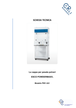
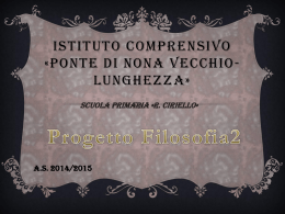
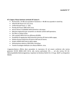
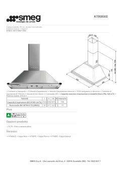
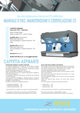
User and maintenance manual and CE certification
80
0
m
m
MANUALE D’USO, MANUTENZIONE E CERTIFICAZIONE CE
810 - 121
0 - 1610 m
m
CAPPE ASPIRANTI
serie mod. C1/C2/C3 - matricola:
prodotto da/produced by:
IRIDE International srl
Via S.Giuseppe 5, Azzano Decimo - PN
Italia
emesso da/issued by
IRIDE International srl
Via S.Giuseppe 5, Azzano Decimo - PN
Italia
h. 2100 mm (da terra)
HOODS
Series models C1 / C2 / C3 – serial number:
emesso il/issued on
Direttiva 89/392/C.E.E. e suoi aggiornamenti..
CAPPE ASPIRANTI da 800 ( C3 ) - 1200 ( C2 ) - 1600 ( C1 )
730 mm
DESCRIZIONE GENERALE CAPPE ASPIRANTI
La cappa è composta da posto saldatura, porte o cassettoni,
saliscendi in cristallo temperato su cornice in alluminio, impianto
di aspirazione, quadro comando e prese di corrente. Il reparto
filtraggio è composto da 2 prefiltri in metallo con costruzione a
nido d’ape e all’interno sono alloggiati altri 2 filtri a carboni attivi
da sostituire periodicamente*. Il carbone attivo è un carbone
che con particolari tecniche viene attivato ad adsorbire.
L’assorbimento è un particolare fenomeno fisico per cui un
solido adsorbente fissa sulla propria superfice un’altra sostanza
(adsorbato). Costruzione metallica esterna in lamiera di acciaio
elettrozincato, interno in acciaio inox. La cornice dei cristalli
temperati è realizzata in alluminio anodizzato. La cappa deve
essere collegata ad una canna fumaria per permettere la
fuoriuscita dei fumi che vengono prodotti dal fornello e dal forno
per cilindri. L’altezza del foro deve essere da terra di 2200mm e
deve avere un diametro di 120mm. La ditta Iride International
s.r.l. non risponde per gli allacciamenti che vengono effettuati
con cavi di spessore inferiore a quanto indicato nello schema
“CENTRALINO”.
FUME HOOD GENERAL DESCRIPTION
The fume hood comprises a welding set, doors or dresser,
vertical sliding tempered crystal sash with aluminium frame,
suction equipment, control panel and plug sockets. The filtering
equipment comprises two metal pre-filters with a honeycomb
pattern and it also hosts 2 activated carbon filters to be
periodically replaced.* Activated carbon is a carbon which,
through specific techniques, acquires a large absorptive
capacity. Absorption is a specific physical phenomenon which
allows an absorbing body to fix on its surface another substance
(adsorbate). The external metal case is made of galvanised
steel plate, whereas stainless steel is used internally. The frame of
the tempered crystal sash is made of anodised aluminium. The
fume hood must be connected to a flue to allow the emission
of the fumes produced by the hot plate and the cylinder
furnace. The hole must be 2,200 mm high from the ground and
the hole diameter must be 120 mm wide. Iride International s.r.l.
is not responsible for any connection carried out with cables
not complying with the minimum thickness required by the
“ELECTRICAL PANEL” diagram.
* il lavaggio dei prefiltri metallici deve avvenire almeno ogni
600 ore di lavoro; la pulizia dovrà essere effettuata con una
vaporiera. Anche i filtri a carboni attivi devono essere sostituiti
ogni 600 ore di lavoro, considerando l’uso medio della cappa
da parte di n.6 utenti.
* the metal pre-filters must be washed at least every 600 working
hours; the cleaning must be performed using a vapour cleaning
machine. Likewise, the activated carbon filters must be replaced
every 600 working hours, considering the average use of the
hood by 6 users.
1986 • 2011
arredamenti per laboratori odontotecnici e studi dentistici
montaggio, uso e manutenzione
COMPONENTI DELLO SCHEMA ELETTRICO
1interruttore diff. puro 2P 25A 0,03A “AC”
2interruttore magn. 1P+N 16A “C”
su cappa da 800 - 1 presa
su cappa da 1200 - 2 prese
su cappa da 1600 - 3 prese
3porta fusibile sezion. 1P 10A 3x38 ritardato.
4interruttore 2P 25A.
5interruttore orario digitale mod. settimanale
6interruttore 2P 25A.
ALTRI COMPONENTI CAPPA
int. 1, spina CE mobile 2P+T 16A 220V
int. 2, prese CE parete 2P+T 16A 220V
int. 3, plafoniera ovale da 60W C/GABBIA
DESCRIZIONE IMPIANTO
L’impianto elettrico varia a seconda del modello scelto
(cappa da 800, 1200, 1600).
Nella cappa da 800 vengono utilizzati cavi della portata
di 4mm2, pertanto la portata massima è di 4500W.
Nelle cappe da 1200 e 1600 vengono utilizzati cavi
della portata di 6mm2 pertanto la portata massima è
di 6000W. Quando si parla di portata massima si intende
l’assorbimento di tutta la cappa ad esempio la cappa
da:
(800) 1 lampada 60W+motore 500W+presa 1-2500W = 3060W
(1200) 1 lampada 60W+motore 500W+presa 1-2500W+presa
2-2500W = 5560W
(1600) 1 lampada 60W+motore 500W+presa 1-2500W+presa
2-2000W+presa 3-1000W = 5560W
ATTENZIONE! La somma totale delle prese non deve superare i
6000W, quindi le varie prese possono avere un valore diverso ma
il valore massimo sopra indicato non deve essere superato.
WIRING DIAGRAM COMPONENTS
1-
residual current operated circuit-breaker
(without over-current release) 2P 25A 0.03A
“AC”
2thermomagnetic switch 1P+N 16A “C”
800 hood - 1 plug socket
1,200 hood - 2 plug sockets
1,600 hood - 3 plug sockets
31P 10A 3x38 delayed fuse disconnector door.
42P 25A switch
5digital time switch – weekly model
62P 25A switch
OTHER HOOD COMPONENTS
switch 1, mobile CE plug 2P+T 16A 220V
switch 2, wall CE plug sockets 2P+T 16A 220V
switch 3, 60W oval overhead light with CAGE
SYSTEM DESCRIPTION
The electrical system changes according to the model
required (800, 1,200 or 1,600 hood).
The 800 hood uses cables with a carrying capacity of 4
mm2, therefore the maximum carrying capacity is 4,500W.
The 1,200 and 1,600 hoods use cables with a carrying
capacity of 6 mm2, therefore the maximum carrying
capacity is 6,000W. The maximum capacity is the electrical
input of the entire hood. For example, the following hoods:
(800) 1 lamp 60W+motor 500W+plug 1-2,500W = 3,060W
(1200) 1 lamp 60W+motor 500W+plug 1-2,500W+plug 22,500W = 5,560W
(1600) 1 lamp 60W+motor 500W+plug 1-2,500W+plug 22,000W+plug 3-1,000W = 5,560W
WARNING! The total sum of the plugs must not exceed
6,000W, hence the various plugs may have different values
but the above mentioned maximum value must never be
exceeded.
CENTRALINO
Fili 220W
Corrugato
L. 1800
L. 1100
2,5
Linea
6
M
2,5
2,5
marrone
A
B
D
N
blu
2
2
2
3
4
blu
N
A
2,5
1,5
blu
marrone
C
D
N
1
M
6m
N
5
6
N
B
2,5
2,5
presa 1
2,5
presa 2
2,5
presa 3
1,5
1,5
lampada
N
M
B
C
aspirazione
pulizia - sostituzione filtro
SCHEMA ELETTRICO - WIRING DIAGRAM
All’interno della scatola stagna ci sono 2 morsetti liberi, marrone e blu; per il collegamento della massa collegare
la barra di rame. All’interno trovate anche un fusibile di ricambio e le istruzioni per l’orologio.
Within the watertight case there are 2 free clamps, brown and blue; in order to connect the ground, connect the
copper rod. A spare fuse and clock instructions are also supplied with the package.
USCITA FUMI - SMOKE OUTLET
Foro Ø 120mm, per la fuoriuscita
dei fumi aspirati.
Ø120 mm hole to let out the
fumes.
(A)- ENTRATA ARIA (facoltativo)
(A)- AIR INLET (optional)
Su questo attacco si può collegare
un tubo Ø 80mm comunicante
con l’esterno per permettere alla
cappa chiusa ermeticamente di
funzionare con riciclo interno.
FILTRAGGIO
Il sofisticato sistema di filtraggio
per polveri pesanti permette che
le polveri vengano convogliate
nell’intercapedine del fianco
destro della cappa.
This connection may be used with
a Ø 80mm pipe communicating
with the outside to allow the
hermetically sealed hood to work
with an internal air recycle.
FILTERING
This sophisticated heavy dust
filtering system allows dusts to be
conveyed into the hollow space
on the right side of the hood.
1
CENTRALINO ELETTRICO
ELECTRICAL PANEL
FILTRO INTERNO - INTERNAL FILTER
Per la sua sostituzione vedi figure
1, 2 e 3.
Procedere con ordine inverso per
riassemblare.
To replace it, see figures no. 1, 2
and 3.
To reassemble, repeat the steps in
reverse order.
2
CHIUSURA ERMETICA
Normalmente sono presenti due
fermi per evitare la chiusura
totale del vetro. Nel caso in cui
l’utilizzatore segua le istruzioni
del punto (A)-ENTRATA ARIA
(consigliato), si possono togliere
i fermi così da permettere la
chiusura ermetica della cappa e
di conseguenza poter utilizzare il
sistema del riciclo interno.
HERMETICAL SEALING
Usually there are two clamps to
prevent the glass from closing
completely. When the user is
following the instructions of item
(A)-AIR INLET (recommended),
the clamps can be removed to
allow for the hermetical sealing
of the hood and consequently to
use the internal recycle system.
3
POSTO SALDATURA
Posto saldatura, regolabile in
attezza e con piano ruotabile a
360°.
WELDING SET
Welding set, adjustable in height
and a 360° revolving table.
CERTIFICAZIONE CE
DICHIARAZIONE DI CONFORMITÀ
Noi IRIDE INTERNATIONAL S.r.l. arredamenti per studi dentistici e laboratori odontotecnici, con sede legale
in Via San Giuseppe 5 - 33082 Azzano Decimo - Località Tiezzo - PN:
DICHIARIAMO SOTTO LA NOSTRA RESPONSABILITÀ CHE IL PRODOTTO CAPPE ASPIRANTI É STATO PROGETTATO
E COSTRUITO IN ESCLUSIVA IN CONFORMITÀ CON LA SEGUENTE NORMA ARMONIZZATA:
CEI EN 60601-1(CEI65-5) del 1991 e suo aggiornamento del 1994
CEI EN 60204-1(CEI 44/5 e 44/6)
E LE RICHIESTE DELLA DIRETTIVA:
2006/42/CE
2006/95/CE
2004/108/CE
IRIDE INTERNATIONAL S.R.L.
DECLARATION OF CONFORMITY
We, IRIDE INTERNATIONAL S.r.l. – furniture for dentist offices and dental laboratories, with registered
headquarters in Via San Giuseppe 5 - 33082 Azzano Decimo - Località Tiezzo - PN:
HEREBY DECLARE UNDER OUR OWN RESPONSIBILITY THAT THE PRODUCT “HOODS” TO WHICH THIS DECLARATION
RELATES WERE DESIGNED AND BUILT IN EXCLUSIVE MANUFACTURING IN CONFORMITY WITH THE FOLLOWING
HARMONISED STANDARDS:
IEC EN 60601-1(IEC 65-5) of 1991 and its 1994 amendments
IEC EN 60204-1(IEC 44/5 and 44/6)
AND THE REQUIREMENTS OF THE DIRECTIVE:
2006/42/CE
2006/95/CE
2004/108/CE
IRIDE INTERNATIONAL S.R.L.
1986 • 2011
IRIDE INTERNATIONAL s.r.l.
Via S. Giuseppe 5 | 33082 Azzano Decimo - PN
tel. +39 0434 633242 | fax +39 0434 632546
[email protected] | www.irideinternational.com
Scaricare