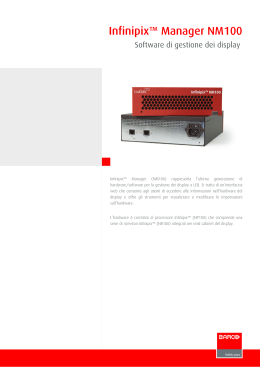
dental
and
medical
Istruzioni per l’uso
Instructions for use
Mode d’emploi
Bedienungsanleitung
Istrucciones para el uso
PHANTOM SX 3
PHANTOM KM 3
equipment
TECNO-GAZ, La ringrazia di aver acquistato un prodotto della sua gamma e la invita alla
lettura, in ogni parte del presente Manuale Istruzione.
All’interno troverà tutte le istruzioni necessarie per un corretto utilizzo del prodotto. Si
prega di seguire attentamente le avvertenze contenute, di conservarlo inalterato,
facilmente reperibile ed accessibile all’operatore.
Il contenuto del presente Manuale può essere modificato, senza preavviso ne ulteriori
obblighi, al fine di includere variazioni e miglioramenti.
È vietata la riproduzione o la traduzione di qualsiasi parte del presente manuale senza il
consenso scritto di TECNO-GAZ.
La informiamo che la ns. Ditta rimane a Sua completa disposizione per fornire notizie e
delucidazioni in merito a tutto quanto concerne l’utilizzo del prodotto.
Grazie e buon lavoro
TECNO-GAZ S.p.A.
TECNO-GAZ wishes to thank you for your purchasing one of its range of products and
you are invited to read this booklet thoroughly.
This booklet contains all of the information necessary to use the product correctly.
Please adhere closely to the notices contained within and conserve the booklet, without
making changes, in a place where it is easy to find and is accessible to the operator.
The contents of this manual can be changed, without warning or additional obligations, so
that the manufacturer can include variations and improvements.
It is prohibited to copy or translate any of this booklet without the written permission of
TECNO-GAZ.
Our Company remains at your complete disposal to provide any kind of information you
may need for operating the appliance.
Again thank you and good work.
TECNO-GAZ S.p.A.
1
DPNF001 Rev.2
INDICE
ITALIANO
7 - 23
INGLESE
24 - 40
2
DPNF001 Rev.2
PAR. 1
DICHIARAZIONE DI CONFORMITÀ CE
EEC CONFORMITY STATEMENT
La sottoscritta - The company: TECNO-GAZ S.p.A. - Strada Cavalli n. 4 - 43038 Sala Baganza, Parma, Italia.
Dichiara, sotto la propria responsabilità, che il FORNO PER PRERISCALDO CILINDRI
Declares under its own responsibility that the PRE-HEATING OVEN FOR CYLINDERS
Nelle version
For versions
PHANTOM SX 3
PHANTOM KM 3
TARGHETTA
PLATE
Costruito da TECNO-GAZ S.p.A., è conforme alle disposizioni legislative che traspongono la Direttiva
Macchine 98/37/CE, la Direttiva Bassa Tensione 93/68/CEE, la Direttiva Compatibilità elettromagnetica
89/336/CEE (classe 1A non idoneo ad uso domestico) e le loro successive modifiche e integrazioni.
Manufactured by TECNO-GAZ S.p.A., complies with the Machine Directive 98/37/CE, the Low Tension
Directive 93/68/CEE, the Electromagnetic Compatibility Directive 89/336/CEE (class 1A inadequate for
household use) and their relative amendments and modifications.
• Riferimento fascicolo tecnico Cod. FT-PN.
• Technical documentation reference code FT-PN.
• Il Sistema Qualità di TECNO-GAZ è conforme alle Norme ISO 13485 e ISO 9001, approvato da DNV (Det
Norske Veritas Italia) Certificato n°CERT-04798-99-AQ-BOL-SINCERT
• TECNO-GAZ quality system complies with the European Standards ISO13485 and ISO 9001, approved
by DNV (Det Norske Veritas Italy) Certificate n°CERT-04798-99-AQ-BOL-SINCERT
Nome - name: Paolo Bertozzi
Posizione - position: Presidente - President
3
DPNF001 Rev.2
PAR. 2
MARCATURA CE
CE MARKING
Il FORNO PER PRERISCALDO CILINDRI è stato esaminato secondo quanto previsto dalla
direttiva 98/37/CE e successive modifiche e integrazioni.
L’avvenuto esame è pubblicizzato dall’apposizione, sulla macchina, della targhetta con
marchio CE (qui di seguito raffigurata) e dalla dichiarazione di conformità che
accompagna il presente libretto.
The PRE-HEATING OVEN FOR CYLINDERS is projected and manufactured according to
requests by the Directive 98/37/CE and its relative amendments and modifications.
The CE label (here below shown) and the Conformity Statement that accompany this
instructions manual bear the technical data resulting from the tests carried out.
TARGHETTA
LABEL
PAR. 3
ELENCO DEI PUNTI VENDITA ED ASSISTENZA
LIST OF RETAILERS AND TECHNICAL ASSISTANCE SERVICES
PER FACILITARE I FREQUENTI AGGIORNAMENTI, L’ELENCO SUDDETTO VIENE
FORNITO SEPARATAMENTE ED ALLEGATO AL PRESENTE LIBRETTO COME
DOCUMENTO DTGF001.
THE ABOVE-MENTIONED LIST IS SUPPLIED SEPARATELY WITH THIS INSTRUCTIONS
MANUAL AS DOCUMENT DTGF001, IN ORDER TO FACILITATE FREQUENT UPDATING.
4
DPNF001 Rev.2
PAR. 4
GARANZIA
L’apparecchio è coperto da garanzia per un periodo di dodici mesi, eccezion fatta delle
parti elettriche e di riscaldamento, per le quali la garanzia ha validità di sei mesi.
Detta garanzia ha inizio dalla data di consegna dell’apparecchio al cliente, comprovata
dalla restituzione del tagliando di garanzia opportunamente compilato, timbrato e firmato
dal rivenditore.
In caso di contestazione, si ritiene valida la data riportata sulla bolla di vendita.
La riparazione o la sostituzione in garanzia di un particolare, avviene ad insindacabile
giudizio della Casa costruttrice e non comprende la trasferta del personale e le spese di
imballaggio e trasporto.
Lampade, fusibili, vetrerie e guasti o danni causati da cattiva manutenzione, negligenza,
imperizia o altre cause non imputabili al costruttore, non sono soggetti a garanzia.
Sono inoltre esclusi da garanzia i componenti soggetti a normale usura.
Non si riconosce il diritto alla sostituzione dell’apparecchio completo.
La garanzia non comporta risarcimento danni diretti e indiretti di qualsiasi natura verso
persone o cose dovuti ad eventuale inefficienza dell’apparecchio.
Non sono compresi risarcimenti per fermo macchina.
La garanzia decade automaticamente qualora l’apparecchio venga manomesso, riparato
o modificato dall’acquirente o da personale non autorizzato da TECNO-GAZ S.p.A.
Per qualsiasi intervento, rivolgersi unicamente al rivenditore di zona oppure ai centri
assistenza indicati dalla Casa costruttrice. I componenti sostituiti in garanzia dovranno
essere rispediti a TECNO-GAZ S.p.A. in porto franco. La mancata restituzione comporta
l’addebito del costo del particolare al richiedente.
WARRANTY
The appliance is warranted for a period of twelve months, excluded electric and warming
up parts for which the warranty covers up to six months.
The warranty begins the date the machine is delivered to the client, such date must
appear on the warranty coupon, which must be properly filled in, stamped and signed by
the retailer and then sent back to TECNO-GAZ S.p.A.
In case of complains, it will be considered valid the date appearing on the delivery note.
Repairing or replacement under warranty conditions of any components will be
exclusively carried out by TECNO-GAZ S.p.A; the warranty does not cover travel
expenses of personnel, neither packaging or transport expenses.
The warranty does not cover lamps, fuses, glassworks and the failure or damages caused
by wrong maintenance, negligence, unskilfulness or any other cause the manufacturer is
not to be hold responsible for.
Those materials subjected to regular wearing out are not covered by the warranty.
TECNO-GAZ S.p.A does not recognise the right to have the whole machine replaced.
The warranty does not meet any request of indemnity for direct or indirect damages
caused to goods and persons, provoked by the inefficiency of the machine.
TECNO-GAZ S.p.A does not recognize any indemnity in case the machine is not used.
5
DPNF001 Rev.2
The warranty will be automatically declined in case the machine is tampered, repaired or
modified by the client or by third parties having not been authorized by TECNO-GAZ
S.p.A.
The purchaser is compelled to contact the retailer or after-sales service centre indicated
by TECNO-GAZ S.p.A. for the repairing. The components replaced during the warranty
period must be sent back to TECNO-GAZ S.p.A. porto franco. In case the replaced
components are not been sent back to TECNO-GAZ S.p.A. the purchaser will be charged
for them.
6
DPNF001 Rev.2
INDICE
1
Dichiarazione di Conformità CE
3
2
Marcatura CE
4
3
Elenco dei punti vendita ed assistenza
4
4
Garanzia
5
5
Caratteristiche tecniche
8
6
Imballo, trasporto e stoccaggio
8
7
Impiego del forno per preriscaldo cilindri
9
8
Descrizione dell’apparecchio
9
9
Istruzioni per l’installazione
9
10
Descrizione comandi
11
11
Programmazione dati
13
12
Allarmi
19
13
Interruzione dell’energia elettrica
20
14
Emissione sostanze nocive durante il funzionamento
20
15
Lavorazioni manuali che possono causare danni
20
16
Accessori di protezione per l’operatore
21
17
Avvertenze, consigli, nozioni utili
21
18
Aspiratore e cappa aspirante
22
19
Rottamazione
22
20
Figure ed illustrazioni
23
7
DPNF001 Rev. 2
PAR. 5
CARATTERISTICHE TECNICHE
CARATTERISTICHE MECCANICHE
PHANTOM KM
PHANTOM SX
Altezza senza aspiratore
480 mm
420 mm
Altezza con aspiratore
640 mm
580 mm
Profondità senza aspiratore
320 mm
280 mm
Larghezza
325 mm
250 mm
Peso
30 Kg
20 Kg
Materiale
Ferro verniciato/Acciaio INOX AISI 304 satinato
Dimensioni utili della camera
Altezza
Profondità
Larghezza
110 mm
160 mm
170 mm
95 mm
160 mm
120 mm
CARATTERISTICHE ELETTRICHE
PHANTOM KM
PHANTOM SX
Tensione di alimentazione
220 V
Frequenza
50 Hz
Fasi
1+Neutro
Corrente fusibile
16 A
10 A
Potenza assorbita
2.4 KW
1.75 KW
Tipo di protezione
PE
Classe
1
Cavo di alimentazione mt.2
2 x 1.5mm2 + Terra
Connettore
16 A + Terra
Temperatura massima
1100 °C
Velocità massima di salita
20 °C/min
23 °C/min
Velocità minima di salita
1°C/min
PAR. 6
IMBALLO, TRASPORTO E STOCCAGGIO
Il FORNO PER PRERISCALDO CILINDRI, ha un peso esiguo ed un volume contenuto,
perciò non necessita di imballaggi eccessivamente articolati.
Protetto da un sacchetto di cellophane, viene posto in un involucro di polistirolo espanso
ed inserito in un contenitore di cartone ondulato, quindi sigillato mediante nastro adesivo.
Il trasporto deve avvenire senza scosse, urti e senza esporre il prodotto imballato
all’umidità.
ATTENZIONE:
Non disperdere il materiale di imballo nell’ambiente. Esso dovrà essere conservato per
essere riutilizzato nel caso in cui fosse necessario rispedire l’apparecchio presso TECNOGAZ per eventuali riparazioni o controlli. I prodotti imballati devono essere custoditi in
luoghi asciutti e ad una temperatura compresa tra (-10 ÷ 40 )°C.
Non è consentita la sovrapposizione di più macchine.
8
DPNF001 Rev. 2
PAR. 7
IMPIEGO DEL FORNO PER PRERISCALDO CILINDRI
Il forno PHANTOM è un apparecchio che viene utilizzato per cuocere i cilindri contenenti il
rivestimento per le microfusioni a cera persa, da impiegarsi esclusivamente nel settore
odontotecnico.
Non è consentito l’utilizzo della macchina per altri scopi o in ambienti non
pertinenti alle caratteristiche dell’apparecchio.
PAR. 8
DESCRIZIONE DELL’APPARECCHIO
Il forno per preriscaldo cilindri PHANTOM, è costituito da due parti indivisibili:
Mobile forno (Pos.151 Fig.1§ 19)
Mobile comandi (Pos.161 Fig.1§ 19)
Il mobile forno è una camera di materiale refrattario contenuta in un involucro
termoisolante.
Una resistenza elettrica posta attorno a tale camera (Pos.100 Fig.3§ 19), produce il calore.
Il controllo della temperatura è affidato ad una termocoppia (Pos.81).
Lo sportello (Pos.153) comprende il refrattario (202), il magnete per la ritenuta dello
sportello (168) e la maniglia per l’apertura (166).
Il mobile comandi contiene l’equipaggiamento elettronico per il controllo della
temperatura, la programmazione delle funzioni ed i comandi.
La parte posteriore del forno è predisposta per l’applicazione meccanica dell’aspiratore
mod. MISTRAL (Pos.195).
L’alimentazione elettrica dell’aspiratore si ottiene collegandolo alla presa apposita pos.92.
La presa pos.91 viene utilizzata per alimentare direttamente la cappa aspirante del
laboratorio.
PAR. 9
ISTRUZIONI PER L’INSTALLAZIONE
Il forno PHANTOM deve essere posizionato sotto una cappa aspirante su un
piano orizzontale stabile, non infiammabile lontano da spruzzi d’acqua e da
materiali infiammabili.
E’ vietato collegare il camino dell’aspiratore ad altri tubi o condotti aspiranti,
in quanto potrebbero creare resistenza all’uscita dei gas, oppure una
eccessiva aspirazione con conseguente perdita di calore nella camera del
forno.
Inserire la spina dell'alimentazione elettrica, pos. 93, in una presa di corrente monofase
ad una tensione di 220V 50Hz.
Detta presa deve erogare una potenza di 3 KW, essere munita di protezione di terra e di
un dispositivo salvavita.
9
DPNF001 Rev. 2
Premere l'interruttore generale Pos. 30, Pag. 9.
Sul display 27 compare OFF.
Sul display 28 appare il numero dell’ultimo programma utilizzato.
Sul display 29 appare il numero 2.
Se invece sul display pos. 27 appaiono altre indicazioni, premere subito il comando
START/STOP,pos. 9, ed appare OFF.
In questa situazione il forno è pronto per essere programmato.
Per comandare l'accensione della cappa aspirante del laboratorio, bisogna collegare la
spina, in dotazione al forno, al motore della cappa ed inserirla nella presa pos.91.
10
DPNF001 Rev. 2
PAR. 10
DESCRIZIONE COMANDI
(Rif. figura pagina successiva)
POSIZIONE
1
2
TASTO
1,2,3…..9,0
FUNZIONE
Tasti numerici
Tasto scelta ciclo
3
4
Tasto scelta fase del ciclo
+
=
Tasto attivazione/disattivazione ventola
5
Tasto lettura tempo di mantenimento impostato
6
Tasto lettura gradiente di salita impostato
7
Tasto lettura temperatura impostata
8
9
Tasto lettura temperatura forno se in fase 1
Tasto lettura tempo residuo se in fase di mantenimento
Tasto partenza/arresto ciclo
10
Tasto conferma dati in programmazione
11
Tasto cancellazione dati in programmazione
12
Tasto funzionalità indicatori su pannello
13
Tasto ingresso in programmazione
POSIZIONE
14
LED
FUNZIONE
Led forno in fase di attesa/accensione differita
15
Led forno in fase di lavoro/forno in funzione
16
Led resistenza forno in funzione
17
Led fase di programmazione in corso
18
19
Vedi figura
Vedi figura
20
Vedi figura
21
Vedi figura
22
Vedi figura
23
Vedi figura
24
Vedi figura
25
Vedi figura
26
Vedi figura
Led fase 1 (attesa/accensione differita)
Led fase 2 (programmazione temperatura e gradiente di
salita fase2 / salita fase2)
Led fase 2 (programmazione tempo mantenimento
fase2 / mantenimento fase2)
Led fase 3 (programmazione temperatura e gradiente di
salita fase3 / salita fase3)
Led fase 3 (programmazione tempo mantenimento
fase3 / mantenimento fase3)
Led fase 4(programmazione temperatura e gradiente di
salita fase4 / salita fase4)
Led fase 4 (programmazione tempo mantenimento
fase4 / mantenimento fase4)
Led fase 5 (programmazione temperatura e gradiente di
salita fase5 / salita fase5)
Led fase 5 (programmazione tempo mantenimento
fase5 / mantenimento fase5)
11
DPNF001 Rev. 2
POSIZIONE
27
DISPLAY
FUNZIONE
Display visualizzazione parametri
28
Display indicazione ciclo
29
Display indicazione fase
30
Accensione / spegnimento apparecchio
12
DPNF001 Rev. 2
PAR. 11 – PROGRAMMAZIONE DATI
Per programmare un ciclo, eseguire le operazioni sotto descritte in modo corretto e
nell’ordine indicato.
11.1. Accensione apparecchio;
11.2. Impostazione ciclo e fase;
11.3. Impostazione temperatura, gradiente di salita e tempo di mantenimento;
11.4. Impostazione temperatura spegnimento ventola oppure tempo accensione ventola
11.5. Impostazione temperatura spegnimento cappa aspirante.
11.1 - Accensione apparecchio
L’accensione dell’apparecchio avviene premendo l’interruttore generale 30; esso si
illuminerà e sul display 27 apparirà il numero indicativo della versione della scheda
elettronica;trascorsi alcuni secondi apparirà la scritta OFF. Tutti i led sono spenti.
Nel caso in cui il display riportasse scritte differenti, premere il pulsante START/STOP per
portare il forno in stato di IDLE-OFF.
11.2 - Impostazione ciclo e fase
All’accensione del forno, sul display 28 appare il numero dell’ultimo ciclo selezionato;
sul display 29 appare il numero dell’ultima fase selezionata.
La scelta del ciclo da programmare (Range da 1 a 0 per 10 cicli) si effettua premendo il
tasto
.
Sul display 28 appare la scritta C.
Premere quindi sulla tastiera numerica il numero di ciclo scelto.
Sul display 28 appare visualizzato il numero digitato.
La scelta della fase da programmare (Range da 2 a 5 per 4 fasi di lavoro) è a libera scelta
dell’operatore; possono essere impostate tutte le 4 fasi oppure alcune di esse possono
essere bypassate.
L’operatore deve comunque impostare sempre la 5a fase, in quanto in tale fase la
temperatura finale viene mantenuta anche dopo la scadenza del tempo di mantenimento
impostato, fino all’interruzione del ciclo tramite il tasto START/STOP.
ESEMPIO: Per impostare 4 fasi, programmare le fasi 2/3/4/5;
Per impostare 3 fasi, programmare le fasi 3/4/5;
Per impostare 2 fasi, programmare le fasi 4/5;
Per impostare 1 fase, programmare la fase 5.
Per procedere all’impostazione della fase di lavoro da programmare, premere il tasto
.
Sul display soprastante comparirà la scritta P.
Premere quindi sulla tastiera numerica il numero della fase scelta.
Il display sopra citato riporterà il numero digitato.
La programmazione delle fasi avviene in modo sequenziale, pertanto se si desiderasse ad
esempio programmare 4 fasi, dopo avere impostato il ciclo, selezionare la fase 2 e
procedere alla programmazione.
La scheda elettronica effettuerà automaticamente il passaggio da una fase all’altra.
Il forno PHANTOM consente all’operatore di unire cicli (l’8 e il 9) permettendo di eseguire
un ciclo a 8 fasi di lavoro (al termine della fase 4 del ciclo 8 il forno passa alla fase 2 del
ciclo 9 senza interruzione).
13
DPNF001 Rev. 2
Questa funzione si attiva premendo il tasto 9 della tastiera numerica con il forno in
IDLE-OFF.
Sul display 27 apparirà la scritta 8 9 che indica la separazione dei due cicli. Per unirli,
occorrerà premere il tasto
oppure il tasto 9 della tastiera numerica. Sul display
apparirà la scritta 8-9, indicante l’unione dei due programmi.
il dato viene confermato e il forno ritorna in stato di IDLE-OFF.
Premendo il tasto
La separazione dei cicli si otterrà rieseguendo le operazioni sopra descritte.
11.3 - Impostazione temperatura, gradiente di salita e tempo di mantenimento fasi 2,
3, 4 e 5
Per ogni fase Di lavoro l’utente può programmare in sequenza: temperatura, gradiente di
salita e tempo di mantenimento.
Per entrare nella modalità di programmazione, premere il tasto
: il display 27 visualizza
la scritta dAtA, mentre il led
lampeggerà ad intermittenza per tutta la durata della
programmazione.
Per dare avvio alla programmazione, premere il tasto
.
Durante la programmazione della fase 2, il display 29 riporta la scritta 2.
Il display 27 visualizzerà la scritta °C e successivamente, dopo alcuni secondi, l’ultima
temperatura impostata; mediante la tastiera numerica, sarà poi possibile immettere il
nuovo valore della temperatura della fase (Es. 300 °C, premere 3-0-0).
Impostando la temperatura a 0, la fase viene ignorata e premendo il tasto
alla successiva.
si passa
Per dare conferma del dato impostato, premere il tasto
.
Sul display 27 comparirà la scritta °C-M e successivamente, dopo alcuni secondi, l’ultimo
gradiente di salita impostato; a questo punto è possibile inserire il nuovo valore
(compreso tra 0 e 30°C/min) digitandolo sulla tastiera numerica (Es. 10 °C/min digitare
1-0).
Inserendo il valore 0, la temperatura salirà alla velocità massima (Con resistenza sempre
attiva).
Durante la programmazione il led 19 di salita fase 2 rimane illuminato.
La conferma del dato avviene premendo il tasto
, mentre il led 19 si spegnerà e si
illuminerà il led 20 indicante lo stazionamento della fase 2.
Sul display 27 apparirà la scritta Hr-Mn e successivamente, dopo alcuni secondi, l’ultimo
tempo di mantenimento impostato; a questo punto si potrà inserire il nuovo valore (00/23
ore – 00/59 minuti) mediante la tastiera numerica (Es. 1 ora e 30 minuti, digitare 1-3-0).
Inserendo il valore 0 non si effettuerà il tempo di mantenimento e si passerà direttamente
alla fase successiva; premendo il tasto
si confermerà il dato.
La fase 2 è ora programmata.
La procedura si ripeterà anche per le fasi successive.
Il display
ed i led della scala indicheranno la fase che si sta programmando.
Al termine della programmazione della fase 5, si procederà alla programmazione della
ventola.
14
DPNF001 Rev. 2
11.4 - Impostazione temperatura di spegnimento ventola oppure tempo accensione
ventola (dove presente)
La ventola può offrire due tipi di programmazione:
Impostazione temperatura di spegnimento ventola;
Impostazione tempo accensione ventola.
Impostazione temperatura di spegnimento ventola
Con questa impostazione la ventola si avvia quando il forno passa in fase di lavoro e si
spegne alla temperatura prestabilita.
Dopo avere confermato la programmazione della fase 5 mediante il tasto
, il display
27 riporterà in sequenza le scritte SUCt e toFF e dopo alcuni secondi apparirà l’ultima
temperatura di spegnimento impostata, mentre sul display 29 apparirà la sigla S.
Mediante la tastiera numerica sarà poi possibile inserire il nuovo valore (compreso tra 1 e
1000 °C).
.
Per la conferma premere il tasto
Impostazione tempo di accensione della ventola
In questo caso la ventola viene attivata durante le fasi di lavoro in qualsiasi momento,
premendo i tasti
e
contemporaneamente.
La programmazione di questo dato avviene solo se si è impostato come temperatura
spegnimento ventola un valore pari a 0 (toFF=0).
La programmazione avviene dopo avere impostato la temperatura di spegnimento
ventola a 0 (toFF=0) e avere confermato con il tasto
.
Sul display 27 appariranno in sequenza le indicazioni SUCt e tIME e dopo alcuni
secondi comparirà l’ultimo tempo di accensione impostato, mentre sul display 29 rimarrà
visualizzata la lettera S.
Mediante la tastiera numerica, si procederà poi ad inserire il nuovo valore (da 1 a 120
min.); confermare poi premendo il tasto
.
La ventola si avvia esclusivamente durante le fasi di lavoro premendo i tasti
e
contemporaneamente e si arresterà dopo il tempo impostato.
Nel caso in cui si volesse arrestare la ventola prima dello scadere del tempo, basterà
ripremere i tasti
e
contemporaneamente.
11.5 - Impostazione temperatura di spegnimento cappa aspirante
Al termine della programmazione della ventola, il display 27 riporterà in sequenza le
scritte Hood e toFF e dopo alcuni secondi apparirà l’ultimo valore di spegnimento
impostato, mentre sul display 29 apparirà la sigla H.
Mediante la tastiera numerica, si procederà poi ad inserire il nuovo valore (Da 0 a
.
1100°C); confermare poi premendo il tasto
Impostando un valore diverso da 0, la cappa si avvierà all’inizio del ciclo di preriscaldo e
si arresterà al valore impostato, riaccendendosi se la temperatura ridiscenderà di 20°C da
quest’ultimo. Con valore pari a 0, l’avviamento della cappa non dipenderà dall’attivazione
del riscaldamento del forno.
Il collegamento della cappa aspirante dovrà essere effettuato da personale
esperto e qualificato.
Il modellato in cera contenuto nei cilindri da preriscaldare brucia durante le
fasi di lavoro, emettendo gas nocivi per l’operatore e l’apparecchio, pertanto
il forno deve essere SEMPRE posizionato sotto una cappa aspirante.
15
DPNF001 Rev. 2
Al termine della programmazione il display 27 riporterà il tempo totale necessario per
l’esecuzione delle fasi di lavoro programmate.
Tutti i led delle fasi si illumineranno ed il display 29 riporterà la lettera t.
Tale dato sarà affidabile solo se si rispetteranno i programmi dei gradienti di salita
secondo i seguenti ranges:
PHANTOM SX
PHANTOM KM
Temperatura
Da temp.ambiente a 300°C
Temperatura
Da 301°C a 600°C
Temperatura
Da 601°C a 1100°C
Max 18 °C/min
Max 17 °C/min
Max 17 °C/min
Max 14 °C/min
Max 13 °C/min
Max 9 °C/min
Per uscire dalla programmazione delle fasi di lavoro premere il tasto
Sul display 27 appare la scritta OFF.
.
I dati impostati rimangono in memoria.
L’operatore può comunque variare i dati impostati entrando in programmazione in
qualsiasi momento.
11.6 - Programmazione partenza
L’operatore ha due possibilità:
Accensione immediata
Accensione differita
Accensione immediata.
Con il forno in OFF scegliere il ciclo e la fase di partenza; premere il tasto
ed il forno
inizierà il riscaldamento.
Accensione differita.
Con il forno in OFF scegliere il ciclo da utilizzare e impostare la fase di partenza 1
premendo il tasto
e digitando 1 sulla tastiera numerica; il display 29 riporterà la cifra 1
per tutta la durata della programmazione dell’accensione differita.
Premere il tasto
. Il led della fase 1 ed il led
Sul display 27 appare “dAY”;il tasto
giorno corrente.
si accendono.
permette di procedere e il display visualizza il
Il giorno può essere cambiato con una selezione sequenziale mediante il tasto
oppure
selezionando i tasti numerici da 1 a 7 (1=Lun; 2=MAr….ecc.) e si conferma il dato con il
tasto
.
Il display 27 riporterà la scritta “Hr.Mn” e successivamente l’ora attuale. Mediante la
tastiera numerica, si imposterà l’ora di accensione (0/23 ore - 0/59 minuti) e si confermerà
il dato mediante il tasto
.
Nel caso di partenza differita, il display 27 presenterà tre diversi casi di visualizzazione:
Se mancano più di 24 ore all’avviamento, apparirà il giorno programmato
Se mancano meno di 24 ore e più di 59 minuti, apparirà l’ora di partenza
unitamente ad un puntino lampeggiante
Se mancano 59 o meno di 59 minuti, lampeggerà il tempo mancante in minuti e
decrementerà di minuto in minuto fino all’avviamento del forno.
rimane illuminato per tutta la durata della fase 1 di accensione differita.
Il led
Alla conclusione del tempo impostato si udirà un segnale acustico che coinciderà con il
16
DPNF001 Rev. 2
passaggio alla fase di lavoro.
Nel caso in cui si intendesse interrompere la partenza ritardata, premere il tasto
Il timer dovrà inoltre essere aggiornato nei cambi ora solare/ora legale e viceversa.
Per effettuare tale operazione occorrerà premere il tasto
Sul display 27 tiME; premendo il tasto
.
con il forno in OFF.
comparirà la scritta SoL (Ora Solare) oppure
la scritta LEG (Ora Legale). Per variare il dato occorrerà premere il tasto
successivamente si confermerà il dato con il tasto
confermare con il tasto
Il forno tornerà in OFF.
e
;comparirà poi il giorno attuale sa
, come per l’ora attuale che comparirà successivamente.
11.7 - Ciclo di preriscaldo
La partenza del ciclo avviene dopo che la partenza sarà stata programmata; pertanto si
avrà o premendo il tasto
(Partenza immediata)oppure allo scadere del tempo
impostato (Partenza differita). Il passaggio dalla fase di attesa a quella di lavoro è
segnalata da un breve segnale acustico.
Il ciclo e la fase di lavoro sono indicati rispettivamente dai display 28 e 29.
Il led
si illumina e rimane acceso per tutta la durata del ciclo di preriscaldo.
Il led
di resistenza attivata si illumina indicando che le resistenze sono soggette ad
erogazione di corrente.
Sulla scala led si si illumina il led inferiore della fase in corso.
Il display 27 riporta in successione la temperatura impostata per la fase in corso e la
temperatura presente all’interno della camera.
Al raggiungimento della temperatura impostata, il forno passa sul tempo di mantenimento
impostato. Il led inferiore della fase si spegne e si illumina quello superiore.
Il led
lampeggia.
Il display 27 riporta in successione il tempo di mantenimento impostato per la fase in
corso e la temperatura presente all’interno della camera.
Ad ogni cambio di fase viene emesso un segnale acustico e si aggiornano la scala dei led
ed il display 29.
Un prolungato segnale acustico alla fine della fase 5 indicherà il termine del ciclo.
La temperatura verrà mantenuta fino a quando non si premerà il tasto
il forno in OFF.
che riporterà
L’operatore potrà comunque interrompere il ciclo avviato premendo il tasto
riportando il forno in OFF. Automaticamente verrà selezionata la fase 2.
,
11.8 - Controlli
Stato di IDLE-OFF
Nello stato di OFF si possono effettuare i seguenti controlli:
:Tenendo premuto il tasto, il display 27 visualizza la temperatura della camera.
: Tenendo premuto il tasto si esegue un esame funzionale di tutti i led e display.
Fase 1
Durante la fase 1 si potranno svolgere i seguenti controlli:
: Tenendo premuto il tasto, il display 27 visualizza la temperatura della camera.
: Se mancano più di 24 ore o meno di 59 minuti dalla partenza programmata
17
DPNF001 Rev. 2
verrà visualizzata sul display l’ora dell’avviamento.
Fasi 2,3,4 e 5
Durante le fasi 2,3,4 e 5 si potranno svolgere i seguenti controlli:
: Tenendo premuto il tasto, il display 27 visualizza la temperatura impostata per
la fase in corso.
: Tenendo premuto il tasto, il display 27 visualizza il gradiente di salita impostato
per la fase in corso.
: Tenendo premuto il tasto durante la salita programmata, il display 27 visualizza
il tempo di mantenimento programmato;durante il tempo di mantenimento, invece,
viene visualizzato il tempo di mantenimento residuo per la fase in corso
In tutti i casi sopra citati, rilasciando il pulsante premuto, il display ritornerà ad
indicare il dato precedentemente visualizzato.
18
DPNF001 Rev. 2
PAR. 12
ALLARMI
12.1 - Allarme apertura portello “oPEn”
In qualsiasi fase si trovi un ciclo di preriscaldo, se viene aperto il portello, la corrente sulle
resistenze viene disattivata ed il display 27 riporta la scritta lampeggiante oPEn.
Alla chiusura il funzionamento verrà ripristinato automaticamente.
12.2 - Allarme temperatura “oVEr”
Se la temperatura impostata è inferiore o uguale a 700°C, l’allarme si attiva ogni
qualvolta durante un ciclo si superano i 750°C.
Se la temperatura impostata è maggiore di 700°C, l’allarme di temperatura si attiva
se il dato impostato viene superato di 50°C per un periodo superiore ai 30 secondi
consecutivi.
L’allarme si attiva ogni qualvolta viene superata la temperatura di 1150°C.
L’allarme si attiva in caso di termocoppia non collegata (Rilevato dopo 30secondi)
Sul display 27 viene visualizzata la scritta oVEr lampeggiante.
L’operatore viene avvisato da un cicalino e viene interrotta la corrente alle resistenze.
Occorre spegnere l’apparecchio mediante l’interruttore generale 30.
Se la causa dell’allarme non viene eliminata, l’allarme si ripresenterà al successivo
avviamento.
Interpellare sempre personale esperto e qualificato per la risoluzione del
problema.
12.3 - Allarme termocoppia invertita “thCO”
Questo allarme si presenta nel caso in cui i cavi di collegamento della termocoppia siano
stati invertiti. Il display visualizza l’allarme thCO ad intermittenza, accompagnato da un
suono, anch’esso intermittente.
L’allarme viene resettato ripristinando il corretto collegamento dei cavi.
Tale operazione deve essere eseguita da personale esperto e
competente,con il cavo di alimentazione scollegato dalla rete elettrica.
12.4 - Allarme batteria ram “rAM”
L’allarme si presenta una volta esaurita la batteria tampone della scheda elettronica ed il
display riporta l’indicazione rAM lampeggiante, accompagnata da un suono intermittente.
L’allarme viene eliminato premendo il tasto
.
Il problema è risolvibile sostituendo la batteria tampone.
Tale operazione deve essere eseguita da personale esperto e competente,
con il cavo di alimentazione scollegato dalla rete elettrica.
19
DPNF001 Rev. 2
PAR. 13
INTERRUZIONE DELL’ENERGIA ELETTRICA.
L’interruzione dell’energia elettrica può comportare le seguenti conseguenze:
13.1 - Durante la fase 1
Il timer continua il suo lavoro, in quanto sulla scheda è presente la batteria tampone. Al
ritorno della corrente, se il tempo non è scaduto, il ciclo riprende l’attesa; se invece il
tempo impostato è scaduto, il ciclo si avvia immediatamente.
13.2 - Durante la salita nelle fasi 2,3,4 e 5.
Al ritorno della corrente il ciclo riprende da dove era stato interrotto, ripristinando la
temperatura dispersa.
13.3 - Durante il tempo di stazionamento nelle fasi 2,3,4 e 5.
La batteria consente di proseguire il tempo e al ritorno della tensione, se il tempo non è
scaduto, prosegue fino al raggiungimento del dato impostato.
Se al ritorno della tensione il tempo è scaduto, il ciclo passa alla fase successiva
ripristinando la temperatura dispersa.
PAR. 14
EMISSIONE DI SOSTANZE NOCIVE DURANTE IL FUNZIONAMENTO
Come già specificato al § 10.5, i cilindri contengono il modellato in cera; questa sostanza,
quando viene riscaldata, brucia e si trasforma in gas altamente tossici e dannosi per il
forno stesso e per l’operatore.
Prima di cuocere i rivestimenti nel forno bisogna togliere la cera in essi contenuta.
Mettendo i cilindri nel deceratore si estrae quasi tutta la cera; una minima parte, tuttavia,
rimane e produce inquinamento.
Pertanto il forno deve essere SEMPRE posizionato sotto una cappa aspirante.
TECNO-GAZ S.p.A. declina ogni responsabilità per danni prodotti a persone o a
cose dovuti a negligenza o imperizia dell'operatore.
PAR. 15
LAVORAZIONI MANUALI CHE POSSONO CAUSARE DANNI.
Tutte le operazioni manuali riguardanti la cottura dei cilindri, possono essere causa di
incidenti di natura termica.
Non e' possibile proteggere l'operatore da questi rischi perché l'impiego di barriere
impedisce l'uso della macchina.
Per evitare o limitare il pericolo di ustioni, l'operatore deve munirsi degli accessori di
protezione descritti nel paragrafo seguente.
TECNO-GAZ S.p.A. declina ogni responsabilità circa i danni causati a persone o a
cose durante lo svolgimento delle operazioni manuali.
20
DPNF001 Rev. 2
PAR. 16
ACCESSORI DI PROTEZIONE PER L’OPERATORE
L'uso del forno PHANTOM richiede i seguenti accessori per proteggere l'operatore:
a) Maschera protezione viso
b) Guanti termici
b) Grembiule termico
c) Occhiali scuri.
Ad eccezione degli occhiali scuri, fornibili a richiesta, i restanti accessori, non sono
fornibili da TECNO-GAZ.
Rivolgersi ad un negozio specializzato.
PAR. 17
AVVERTENZE, CONSIGLI, NOZIONI UTILI
Per mantenere il forno in buona efficienza, si consiglia di non utilizzarlo alla massima
temperatura per tempi eccessivamente prolungati.
Prima di spegnere il forno tramite l’interruttore generale, premere il tasto
,
riportandolo in stato di IDLE OFF, riscontrabile dalla scritta OFF visualizzata sul display
27.
È di fondamentale importanza l’utilizzo di pinze idonee per inserire ed estrarre i cilindri
nella camera del forno.
Per le operazioni di pulizia, utilizzare un panno asciutto ed un detergente liquido non
infiammabile. Asciugare con un panno morbido.
Non posizionare per alcun motivo sotto getto d’acqua. Le operazioni di
pulizia devono essere effettuate con l’interruttore generale (30) spento ed il
cavo di alimentazione scollegato dalla rete elettrica.
Non appoggiare oggetti sul cavo di alimentazione e non posizionare detto cavo in luoghi
ove possa essere calpestato o essere d’intralcio.
In caso di prolungata inattività scollegare il cavo di alimentazione.
Nel caso di trasporti, utilizzare l’imballo originale; il forno deve essere imballato freddo.
21
DPNF001 Rev. 2
PAR. 18
ASPIRATORE E CAPPA ASPIRANTE
Applicazione dell'aspiratore.
Per applicare l'aspiratore mod. MISTRAL, art.6094/F, bisogna seguire le indicazioni
allegate all'aspiratore stesso.
Non è consentito l'uso di altri tipi di aspiratori anche se adattabili.
La trasgressione di quanto sopra comporta automaticamente l'annullamento della
garanzia e della responsabilità TECNO-GAZ per eventuali danni prodotti a persone o
a cose.
Collegamento alla cappa aspirante.
Il collegamento è possibile solo se le caratteristiche elettriche dell'aspiratore della cappa
sono le seguenti:
Tensione 220V 50Hz Monofase.
Potenza max 0.5 KW.
Con il forno PHANTOM viene fornita la spina elettrica da inserire nella relativa presa
pos.91.
Detta spina deve essere collegata con cavo flessibile, avente una sezione minima di 1,5
mm² e dotato di conduttore di terra, direttamente al motoventilatore della cappa.
Il circuito di alimentazione della cappa, all'interno del forno, è dotato di fusibile di
protezione con corrente nominale di 3A, se la potenza del motore supera quella
sopraindicata, detti fusibili interrompono il circuito.
ATTENZIONE:
L’applicazione dell'aspiratore deve essere eseguita da personale autorizzato
TECNO-GAZ e comporta la dichiarazione di conformità alla direttiva macchine 98/37
CE.
La dichiarazione viene rilasciata con il libretto uso e manutenzione solo da
TECNO-GAZ.
Anche il collegamento con la cappa aspirante comporta la dichiarazione di
conformità alla direttiva 98/37 CE; in questo caso detta dichiarazione deve essere
fatta dal responsabile della ditta in cui si trovano le macchine.
PAR. 19
ROTTAMAZIONE
Il forno PHANTOM è costruito con materiali ferrosi riciclabili.
Il coibente termico che avvolge la camera del forno ed i refrattari non contengono
amianto o suoi derivati e quindi si possono consegnare alle imprese di smaltimento rifiuti.
I componenti elettronici e la batteria,contenuti nella scheda, bisogna affidarli a ditte
autorizzate allo smaltimento di detti componenti.
NON LASCIARE L'APPARECCHIO O SUE PARTI IN LUOGHI NON CUSTODITI O IN
POSIZIONI PERICOLOSE.
22
DPNF001 Rev. 2
PAR. 20
FIGURE ED ILLUSTRAZIONI
23
DPNF001 Rev. 2
INDEX
1
EEC Conformity statement
3
2
CE Marking
4
3
List of retailers and technical assistance services
4
4
Warranty
5
5
Technical features
25
6
Instructions for packaging, transport and storage
25
7
Intended use of the pre-heating oven for cylinders
26
8
Description of the appliance
26
9
Instructions for installating the appliance
26
10
Description of the controls
28
11
Instructions for programming data
30
12
Alarms
36
13
Interruption of the electric power
37
14
Harmful substances emitted by the equipment during the functioning
37
15
Manual operations which may cause damages
37
16
Safety equipment for the operator
38
17
Warning, suggestions and useful information
38
18
Aspirator and suction hood
39
19
Scrapping
39
20
Figures and pictures
40
24
DPNF001 Rev. 2
PAR. 5
TECHNICAL FEATURES
Height without aspirator
Height with aspirator
Depth without aspirator
Width
Weight
Material
MECHANICAL FEATURES
PHANTOM KM
PHANTOM SX
480 mm
420 mm
640 mm
580 mm
320 mm
280 mm
325 mm
250 mm
30 Kg
20 Kg
Vernished iron/Silked steel INOX AISI 304
Useful dimensions of the chamber
Height
Depth
Width
Supplied tension
Frequency
Phases
Fuse current
Absorbed power
Type of protection
Class
2 mt. Power supplying cable
Connector
Maximum temperature
Max. increasing speed
Min. increasing speed
110 mm
160 mm
170 mm
95 mm
160 mm
120 mm
ELECTRICAL FEATURES
PHANTOM KM
PHANTOM SX
220 V
50 Hz
1+Neutral
16 A
10 A
2.4 KW
1.75 KW
PE
1
2 x 1.5mm2 + earth
16 A + earth
1100 °C
20 °C/min
23 °C/min
1°C/min
PAR. 6
INSTRUCTIONS FOR PACKAGING, TRANSPORT AND STORAGE
The PRE-HEATING OVEN FOR CYLINDERS does not need any special packaging since it
is very small and does not weight much.
The equipment is sent protected by a cellophane bag, wrapped in a foam polystyrene
cover, placed within a corrugated cardboard box and sealed with adhesive tape.
Make sure the appliance is not bumped and shaked during transport operations; the
packed product has to be stored in a humidity free place.
ATTENTION:
Do not abandon packaging equipment in the environment. Packed equipment has to be
saved in case it becomes necessary to send the appliance back to TECNO-GAZ for
repairs or controls. The packed equipment has to be kept in a dry place and at a
temperature between -10 ÷ 40 °C.
Do not absolutely lay the machine one on top of the other one
25
DPNF001 Rev. 2
PAR. 7
INTENDED USE OF THE PRE-HEATING OVEN FOR CYLINDERS
The oven PHANTOM is used for baking cylinders contain the lining for investment
precision casting; the appliance has to be used only in odonthotechny field.
Do not absolutely use the appliance for other purposes different from those
afore indicated; neither use the appliance in fields different from
odonthotechny.
PAR. 8
DESCRIPTION OF THE APPLIANCE
The PHANTOM pre-heating oven for cylinders is composed by two indivisible
components:
Oven cabinet (Pos.151 Fig.1§ 19)
Controls board (Pos.161 Fig.1§ 19)
The oven cabinet is a chamber manufactured in refractory material, contained in a thermal
insulating lining.
An electric resistance, placed around the chamber (Pos.100 Fig.3§ 19), produces heat.
A thermocouple controls the temperature (Pos.81).
The door (Pos.153) includes the refractory component (202), the magnet for the door
blocking device (168) and the handle for the opening (166) the door.
The controls board includes the electronical equipment for controlling the temperature,
the programming of the functions and the ontrols.
The aspirator mod. MISTRAL (Pos.195) may be connected to the oven’s rear part.
Connect the aspirator to the plug pos.92 to supply power.
The plug pos.91 is used to supply power to the laboratory’s suction hood.
PAR. 9
INSTRUCTIONS FOR THE INSTALLATING THE APPLIANCE
The oven PHANTOM has to be positioned under a suction hood, laying on a
steady not flammable horizontal plane, far from water splashes and
flammable materials.
Do not absolutely connect the aspirator hood to any other type of pipes or
suctioning conduits, since they may obstruct the gases outlet, or otherwise
an excessive aspiration may cause a waste of heat inside the oven’s
chamber.
Connect the electric power plug, pos. 93, to a monophase outlet having a voltage of 220V
50Hz.
This outlet has to supply 3 KW power, it has also to be equipped with an earthing wire
and a safety device.
Push the main switch Pos. 30, Pag. 9
The display 27 shows OFF.
The display 28 shows the number of last program used.
The display 29 shows 2.
In case the display pos. 27 shows any other message press the START/STOP control,
26
DPNF001 Rev. 2
pos. 9, to display the message OFF.
Now the oven is ready to be programmed.
Connect the plug the oven is supplied with to the suctioning hood motor, then insert the
plug in the outlet pos.91 to start up the suction hood.
27
DPNF001 Rev. 2
PAR. 10
DESCRIPTION OF THE CONTROLS
Refer to figure in next page
POSITION
1
2
KEY
1,2,3…..9,0
3
4
FUNCTION
Numerical keys
Key for selecting cycle
Key for selecting cycle phase
+
=
Fan on/fan off key
5
Key for reading the set holding time
6
Key for reading the set increasing gradient
7
Key for reading the set temperature
8
9
Key for reading the oven temperature when in phase 1
Key for reading the remaining time when in holding time
Start/Stop key
10
Key for confirming the programming data
11
Key for cancelling the programming data
12
Key used for controlling the functioning state of indicators
13
Key for gaining access to programming mode
POSITION
14
LED
FUNCTION
“Oven in holding phase/deleted starting” led
15
“Oven in working phase/oven operating” led
16
“Oven resistance operating” led
17
“Programming phase in course” Led
18
19
See figure
See figure
20
See figure
21
See figure
22
See figure
23
See figure
24
See figure
25
See figure
26
See figure
“Phase 1” led (waiting time /deleted starting up)
“Phase 2” led (programming of temperature and increasing
gradient in phase 2/ increasing temperature in phase 2)
“Phase 2” led (programming of holding time in phase 2
/ holding time in phase 2)
“Phase 3” led (programming of temperature and increasing
gradient in phase 3 / increasing temperature in phase 3)
“Phase 3” led (programming of the holding time in phase
3
/ holding time in phase 3)
“Phase 4” led (programming of temperature and increasing
gradient in phase 4 / increasing temperature in phase 4)
“Phase 4” led (programming of holding time in phase 4 /
holding time in phase 4)
“Phase 5” led (programming of temperature and increasing
gradient in phase 5 / increasing temperature in phase 5)
“Phase 5” led (programming of holding time
In phase 5 / holding time in phase 5)
28
DPNF001 Rev. 2
POSITION
27
DISPLAY
FUNCTION
Parameters display
28
Cycle display
29
Phase display
30
Starting up / Stop
29
DPNF001 Rev. 2
PAR. 11
INSTRUCTIONS FOR PROGRAMMING DATA
To program a cycle you need to carry out the operations here below described correctly
and to follow the order indicated:
11.1. Start up the appliance;
11.2. Set the cycle and the phase;
11.3. Set the temperature, the increasing gradient and the holding time;
11.4. Set the temperature to which the fan will go off/on.
11.5. Set the temperature to which the suction hood will go off.
11.1 - Starting up the appliance.
Press the main switch 30 to start up the appliance; the main switch will light on and the
display 27 will show the printed circuit version number; wait a few seconds for the display
to show OFF. Now all leds will be off.
In case the display shows a different message, press the START/STOP push-button to
set the oven to IDLE-OFF state.
11.2 - Setting the cycle and the phase.
When you start up the oven the display 28 will show the number of the last selected cycle;
and the display 29 will show the number of the last selected phase.
Press the key
to select the cycle (Range from 1 to 0 for 10 cycles).
The display 28 will show the letter C.
Now press the number of the cycle selected on the digit keyboard.
The display 28 shows the number selected.
The operator may now select the phase he wants to program (Range from 2 to 5 for 4
operating phases); the operator may set all 4 phases or bypass some of them.
The 5a phase has, in any case, to be set since during this phase the final temperature is
kept constant, even after the set holding time is over, until you stop the cycle by means of
the START/STOP push-button.
EXAMPLE: Program the phases 2/3/4/5 for setting 4 phases;
Program the phases 3/4/5 for setting 3 phases;
Program the phases 4/5 for setting 2 phases;
Program the phase 1 for setting the phase 5.
Press the key
to set the operating phase you want to program.
The display above it will show the letter P.
Press now the number of the phase you want to select on the digit keyboard.
The afore mentioned display will show the selected number.
The programming of the phases takes place sequentially, therefore if you want to
program 4 phases, for example, set first the cycle, set then the phase 2 and afterwards
carry out the programming.
Phases will scroll automatically thanks to the printed circuit the appliance is equipped
with.
The oven PHANTOM allows you to unite cycles (8 and 9) so to be able to execute a cycle
with 8 operating phases (at the end of phase 4 of cycle 8, the oven passes directly to
phase 2 of cycle 9).
30
DPNF001 Rev. 2
To enable this function pres the key 9 on the numerical keyboard when the oven is in
IDLE-OFF state.
The display 27 will show the digits 8 9 which means that two cycles are separated. To
unite the cycles press the key
or the key 9 on the digit keyboard. The display will show
the digits 8-9 which means that the two programs are united.
and the oven will go back to IDLE-OFF state.
To confirm press the key
Carry out again the afore described operations to separate the cycles you want to.
11.3 - Setting of temperature, increasing gradient and holding time in phases 2, 3, 4
and 5.
You may program in sequence: the temperature, the increasing gradient and the holding
time for each operating phase.
Press the key
to gain access to programming mode; the display 27 will show the
message dAtA, while the led
will blink throughout all the period the programming
phase lasts.
Press the key
to start the programming.
During programming of phase 2 the display 29 will show the digit 2.
The display 27 will show the message °C and, after a few seconds, the last set
temperature will be displayed; to enter the new value of the phase temperature use the
digit key-board (For ex. if you want to enter 300 °C, digit 3-0-0).
If you set the temperature to 0 the phase will be ignored and if you press the key
program will pass to next phase.
the
To confirm the set data press the key
.
The display 27 will show the message °C-M and, after few seconds, the last set increasing
gradient will be displayed; now you may enter the new value (between 0 and 30°C/min)
by means of the digit key board (For ex. if you want to enter 10 °C/min,digit 1-0).
Temperature will increase to the maximum speed when you enter the value 0 (with
resistance always operating).
The led 19 that signals the increasing in phase 2 will keep alighted throughout the whole
programming phase.
To confirm the data press the key
, the led 19 will go off and the led 20 will go on to
indicate the phase 2 has become stable.
The display 27 will show the message Hr-Mn and, after few seconds, the last set holding
time will be displayed; now you may enter the new value (00/23 hours – 00/59 minutes) by
means of the digit key-board (For ex. digit 1-3-0 for entering 1 hour and 30 minutes).
If you enter the value 0 the holding time will be ignored and the program will pass directly
to the next phase; press the key
to confirm the data.
Now the phase 2 is programmed.
Carry out the same procedure for setting the next phases.
The display
and scale led will show the number of the phase being programmed.
At the end of the programming operations of phase 5, you may program the fan.
31
DPNF001 Rev. 2
11.4 - Setting the temperature the fan will stop at or the time fan will be started up (if
supplied)
The fan has two type of programming phases:
Setting of the temperature the fan will stop at;
Setting the time the fan will be started up.
Setting of the temperature the fan will stop at
The fan, thanks to this setting, starts up when the oven enters in the operating phase and
stops when the set temperature has been reached.
Press the key
to confirm the programming of phase 5, the display 27 will show the
messages SUCt and toFF in sequence and, after a few seconds, the last stop
temperature set for the fan, while the display 29 will show the letter S.
Enter the new value by means of the digit keyboard (between 1 and 1000 °C).
Press the key
to confirm data.
Setting the time the fan will be started up
In this case to start the fan anytime throughout the operating phases, press at the same
and
.
time the keys
This data may be programmed only when the value entered for fan stop temperature be 0
(toFF=0).
Set to 0 (toFF=0) the fan stop temperature and confirm the data pressing the key
to
execute the programming.
The display 27 will show the messages SUCt and tIME in sequence and, after a few
seconds, the last set starting time, while the display 29 will show the message S.
Enter the new value (from 1 to 120 min.) by means of the digit keyboard; press the key
to confirm.
To start the fan press at the same time the keys
and
fan will stop when the set temperature will be reached.
Press at the same time the keys
time is over.
and
only during operating phases;
in case you want to stop the fan before the
11.5 - Setting of suction hood stop temperature.
When you have finished programming the fan, the display 27 will show the messages
Hood and toFF and, after a few seconds, the last set stop value will be displayed, while
the display 29 will show the letter H.
Enter the new value (from 0 to 1100°C) using the digit keyboard; press the key
to
confirm data.
If you set a value different from 0, the suction hood will start up at the beginning of the
pre-heating cycle and will stop when the set temperature has been reached; the suction
hood will start again in case the temperature falls 20°C under the set temperature value. In
case the set value is 0, the starting up of the suction hood will not depend on the starting
of pre-heating oven.
The connection of the suction hood has to be carried out only by well-trained
and qualified personnel.
Since during operating phases the investment pattern, contained in the
cylinders to be heated up, burns and emits harmful gases for the operator and
the appliance, the oven has to be ALWAYS positioned under a suctioning hood.
32
DPNF001 Rev. 2
At the end of the programming phase the display 27 will show the total time necessary for
the programmed operating phases to be executed.
All the led of the phases will be alighted and the display 29 will show the letter t.
This data will be considered trustable only in case the programs of the increasing
gradients will be carried out according to the following ranges:
PHANTOM SX
PHANTOM KM
Temperature
From ambient temper. to 300°C
Temperature
From 301°C to 600°C
Temperature
From 601°C to 1100°C
Max 18 °C/min
Max 17 °C/min
Max 17 °C/min
Max 14 °C/min
Max 13 °C/min
Max 9 °C/min
Press the
key to go out from the operating phases programming mode.
The display 27 will show the message OFF.
The set data are kept in memory.
You may change the set data anytime by entering in programming mode.
11.6 - Programming the starting up
You have two possibilities:
Immediate start up
Delayed start up
Immediate start up.
key
Select the cycle and the starting phase when the oven is in OFF state; press the
for starting the oven pre-heating phase.
Delayed start up.
When the oven is in OFF state, select the cycle and set the starting phase 1 by pressing
the
key and digiting 1 on the digit key-board; the display 29 will show 1 throughout all
the programming phase of the delayed start up.
Press the
key. The led of phase 1 and the led
will go on.
The display 27 will show the message “dAY”; to procede press the key
display will show the current date.
The date may be changed by sequential selection using the
and the
key or by pressing the
digit key 1 to 7 (1=Monday; 2=Tuesday….etc.) and then pressing the key
to
confirm the data.
The display 27 will show the message “Hr.Mn” and then the actual time. Set the starting
up hour (0/23 hours - 0/59 minutes) using the digit keyboard and confirm the data by
means of the key
.
For the delayed start up the display 27 will show one of these three following messages:
If it’s more than 24 hours to the starting up, the display will show the programmed
day.
If it’s less than 24 hours and more than 59 minutes to the starting up, the display
will show the starting hour with a blinking point.
If it’s 59 minutes or less than that to the starting up, the display will show the
minutes blinking left to the starting up and it will show the decreasing time (minute
by minute) until the oven stars.
The led
keeps alighted throughout all phase 1 of the delayed start up.
33
DPNF001 Rev. 2
At the end of the set time you will hear an acoustic signal that means the passage to the
operating time is completed.
Press the
key in case you want to stop the delayed start up.
The timer will need to be update when apparent time/ standard time change.
Press the key
when the oven is in OFF state to carry out this operation.
The display 27 shows tiME; press the key
and the display will show the message
SoL (apparent time) or the message LEG (standard time). Press the key
data and then press the key
to change the
to confirm it; the display will show the actual day to be
confirmed by using the key
, as for the actual time which will be displayed
afterwards.
Then the oven will go in OFF state.
11.7 - Pre-heating cycle.
The pre-heating cycle starts only if the cycle start up has been programmed before;
therefore to start the cycle press the key
(Immediate start up) or wait for the set time
to be over (Delayed start up). A short acoustic signal means the passage from waiting
phase to operating phase has been completed.
The displays 28 and 29 will show the cycle and operating phase.
The led
goes on and keeps alighted throughout the whole pre-heating cycle.
The led
of activate resistance goes on to indicate the resistances are supplied with
power.
The lower led of the current phase on the scale of leds gets alighted.
The display 27 will show the set temperature for the current phase and the temperature
inside the chamber in sequence.
When the set temperature has been reached the oven passes to the set holding time. The
lower led of the phase goes off and the upper one gets alighted.
The led
blinks.
The display 27 will show the set holding time for the current phase and the temperature
inside the chamber in sequence.
Every time the phase changes, an acoustic signal goes on and the scale of leds and
display 29 get updated.
An long acoustic signal warns the cycle is concluded at the end of phase 5.
The temperature will be kept constant until you press the key
back to OFF state.
However you can stop the cycle by pressing the key
state. Then automatically the phase 2 will be selected.
, that will set the oven
so setting the oven to OFF
11.8 - Checks.
IDLE-OFF state
When the oven is in OFF state you will be able to carry out the following controls:
: if you keep this key pressed the display 27 will show the temperature inside
the chamber.
: if you keep this key pressed a general test of all the leds and displays will be
executed.
Phase 1
During the phase 1 it will be possible to carry out the following controls:
34
DPNF001 Rev. 2
: if you keep this key pressed the display 27 will show the temperature inside
the chamber.
: if it’s more than 24 hours or less than 59 minutes to the programmed start up,
the display will show the starting up hour.
Phases 2,3,4 and 5
During the phases 2,3,4 and 5 it will be possible to carry out the following controls:
: if you keep this key pressed the display 27 will show the temperature set for
the current phase.
: if you keep this key pressed the display 27 will show the set increasing
gradient for the current phase.
: if you keep this key pressed during the set temperature increase the display 27
will show the set holding time; while during the holding time the display will show
the remaining holding time of the current phase.
In all the cases afore described, if you release the key the display will show the
previously displayed data.
35
DPNF001 Rev. 2
PAR. 12
ALARMS
12.1 - Alarm for door open “oPEn”.
In case the door is opened during any of the phases of the pre-heating cycle, power
supplied to the resistances will be cut off and the display 27 will show the blinking
message oPEn.
Operations will be automatically restored when the door is be closed again.
12.2 - Temperature alarm “oVEr”.
If the set temperature is lower or equal to 700°C, the alarm will go on everytime the
temperature increases over 750°C during a cycle.
If the set temperature is higher than 700°C, the temperature alarm will go on
whenever the temperature increases 50°C over the set data for more than 30
consecutive seconds.
Every time the temperature is higher than 1150°C the alarm goes on.
In case the thermocouple is not connected the alarm goes on (read after 30
seconds)
The display 27 will show the blinking message oVEr.
A buzzer warns the operator and power supplied to the resistances is cut off.
Switch off the appliance by means of the main switch 30.
If the cause of the alarm has not been removed, the alarm will go on again the next time
the appliance is started up.
Ask advice only to expert and qualified personnel for any problem you could
find.
12.3 - Alarm for inverted thermocouple “thCO”.
This alarm will go on in case the connection cables of the thermocouple are inverted. The
display will show the blinking alarm thCO accompanied by an acoustic signal.
Connect the cables correctly to reset the alarm.
This operation has to be carried out only by well-trained and qualified
personnel and only after having disconnected the power supply cable from
the electric system.
12.4 - Alarm for ram battery “rAM”.
The alarm will go on when the buffer battery of the printed circuit is discharged and the
display will show the blinking message rAM accompanied with an acoustic signal. Press
the key
to reset the alarm.
Replace the buffer battery to solve the problem.
This operation has to be carried out only by well-trained and qualified
personnel and only after having disconnected the power supply cable from
the electric system.
36
DPNF001 Rev. 2
PAR. 13
INTERRUPTION OF THE ELECTRIC POWER
Failure of the electric power may be the cause the following consequences:
13.1 - During phase 1
The timer keeps counting since the printed circuit is equipped with the buffer battery.
When the electric power is supplied again the the cycle timer continues counting the
waiting time if it is not over; if otherwise the set time is over the cycle starts immediately.
13.2 - During the increasing temperature in phases 2,3,4 and 5.
When the electric power is supplied again, the cycle starts from where it was when power
failed and dispersed temperature gets restored.
13.3 - During the holding time in phases 2,3,4 and 5.
The battery allows the holding time to be continued and when the electric power is
supplied again, if the time is not over yet, it the timer keeps counting until the set data is
reached.
In case the electric power is supplied again when the time is over, the cycle passes
directly to the next phase restoring the dispersed temperature.
PAR. 14
HARMUL SUBSTANCES EMITTED BY THE EQUIPMENT DURING THE
FUNCTIONING
As described in § 10.5, the cylinders contain the investment pattern; when heated up this
substance burns and emits toxic and harmful gases both for the appliance and the
operator.
Remove the wax contained in the lining before backing them.
Most of the wax is taken out by placing the cylinders in the de-waxer; however a minimum
part of wax remains inside the cylinders and produces pollution.
Therefore the oven has to be positioned ALWAYS under a suction hood.
TECNO-GAZ S.p.A. is not to be hold responsible for damages to goods and persons
caused by negligence or unskilfulness of the operator.
PAR. 15
MANUAL OPERATIONS WHICH MAY CAUSE DAMAGES
All manual operations regarding the backing of cylinders may cause burns.
It is not possible to protect the operator by placing protective barriers around the
appliance, since they will not allow to use the appliance correctly.
To avoid or reduce the risk of burns the operator has to be equipped with the special
protective equipment described in the following paragraph.
TECNO-GAZ S.p.A. is not to be hold responsible for damages to goods and persons
caused during manual operations.
37
DPNF001 Rev. 2
PAR. 16
SAFETY EQUIPMENT FOR THE OPERATOR
The operator has to wear the following equipment to use the oven PHANTOM in safety
conditions:
a) Protective mask
b) Thermal gloves
b) Thermal apron
c) Protective glasses.
Those accessories, with the exception of protective glasses, which could be supplied if
requested, are not supplied by TECNO-GAZ.
Turn to a specialized shop.
PAR. 17
WARNINGS, SUGGESTIONS AND USEFUL INFORMATION
We suggest to avoid heating the oven to its maximum temperature for too long to keep it
in best efficiency conditions.
Press the key
to set the oven to IDLE OFF state, (see if the message OFF is
displayed in the display 27), before switching off the oven by means of the main switch.
It is very important to use special pliers for inserting in and taking out the cylinders from
the oven chamber.
Use a dry cloth with a not flammable liquid detergent to clean the appliance. Dry the
appliance by using a soft cloth.
Never wash the appliance with a jet of water. Cleaning operations have to be
carried out with the main switch off (30) and the supplying cable
disconnected from the power supply system.
Do not lean objects on the supplying cable and do not position the cable in places where
it could be trampled on or disturb operations.
Unconnect the supplying cable in case the appliance is not to be used for a long time.
Use the original packaging in case the oven has to be moved; the oven has to be packed
only when cold.
38
DPNF001 Rev. 2
PAR. 18
ASPIRATOR AND SUCTIONING HOOD.
Connecting the aspirator.
Follow the indications enclosed with the aspirator mod. MISTRAL, art.6094/F to assemble
it correctly.
Do not use any other type of aspirators even if suitable.
TECNO-GAZ is not to be hold responsible for damages to goods and persons if the
afore described request is not met; furthermore this means the warranty will be
automatically declined.
Connecting the suctioning hood.
To connect the suctioning hood the following electrical features have to be met:
Tension 220V 50Hz Monophase.
Max. power of 0.5 KW.
The plug to be inserted in the outlet pos.91 is supplied with the oven PHANTOM.
This plug has to be directly connected to the hood motorfan by means of a flexible cable,
having a minimum section of 1,5 mm² and equipped with earthing wire.
The hood feeding circuit, located within the oven, is equipped with a protection fuse with
nominal power of 3A; if the power of the motor is superior to afore indicated value, the
fuses interrupt the circuit.
ATTENTION:
The aspirator has to be assembled only by personnel authorized by TECNO-GAZ;
this operation has to be accompanied by the conformity statement according to the
Machines Directive 98/37 CE.
The conformity statement is supplied with the use and instructions manual only by
TECNO-GAZ.
Furthermore the connection to the suctioning hood has to be accompanied by the
conformity statement according to the Machine Directive 98/37 CE; in this case the
conformity statement has to be signed and made liable by the company where the
machines are installed.
PAR. 19
SCRAPPING
The oven PHANTOM is manufactured using ferrous materials that can be recycled.
Thermal insulating the oven is wrapped with and the refractory material do not contain
asbestos or its derivatives therefore can be entrusted to a company specialized in waste
disposal.
The battery and electronical components, contained in the printed circuit, have to be
entrusted to a company specialized in disposing of those product.
DO NOT LEAVE THE APPLIANCE OR ANY OF ITS PARTS IN UNATTENDED PLACES
OR IN DANGEROUS POSITIONS.
39
DPNF001 Rev. 2
PAR. 20
FIGURES AND PICTURES
OVEN CABINET
HANDLE
153 DOOR
REAR VIEW
ASPIRATOR
THERMOCOUPLE
RESISTANCE
SUCTION HOOD INLET
ASPIRATOR INLET
40
DPNF001 Rev. 2
dental
and
medical
equipment
TECNO-GAZ S.p.A.
Strada Cavalli N°4 • 43038 • Sala Baganza • Parma • ITALIA
Tel. +39 0521 83.39.26 r.a.
Fax. +39 0521 83.33.91
www.tecnogaz.com
Il presente manuale
deve
sempre
accompagnare
il
prodotto,
in
adempimento
alle
Direttive
Comunitarie
Europee.
TECNO-GAZ, si riserva il
diritto
di
apporre
modifiche al presente
documento senza dare
alcun pre-avviso.
La ditta TECNO-GAZ si
riserva la proprietà del
presente documento e
ne vieta l’utilizzo o la
divulgazione
a
terzi
senza
il
proprio
benestare
This
manual
must
always be kept with the
product, in complying
with the Directives of
European Community.
TECNO-GAZ
reserves
the right to modify the
enclosed
document
without notice.
TECNO-GAZ
reserves
the property of the
document and forbids
others to use it or
spread it without its
approval.
Ce manual doit être
gardé avec le produit,
conformément
aux
Directives
de
la
Communauté
Européenne.
TECNO-GAZ se réserve
la faculté de faires des
changements
à
ce
document sans aucun
préavis.
TECNO-GAZ se réserve
la propriété de ce
document
et
en
empêche l’utilisation ou
la divulgation sans son
consentement.
Dieses
Handbuch ist
nach den CEE Normen
immer mit dem Produkt
auszuliefern.
TECNO-GAZ behält sich
Änderungen an dem
Dokument vor.
Der
Inhalt
dieses
Dokumentes
ist
urheberrechtlich
geschützt.
Jede
weitergehende
Verwendung,
insbesondere jede Form
der
gewerblichen
Nutzung
sowie
die
Weitergabe an Dritte auch in Teilen oder in
überarbeiteter Form ist ohne Zustimmung
der Firma TECNO-GAZ
untersagt.
Este
manual
debe
siempre acompañar el
producto,
en
cuplimiento
a
las
Directivas
Europeas.TECNO-GAZ,
se reserva de derechi
de
aportar
modificaciónes a este
documento sin ningum
aviso.
La impresa TECNO-GAZ
se reserva la propiedad
de este documento y
veda el utilizzo o la
divulgación a terceros
sin su aprobación.
Scaricare