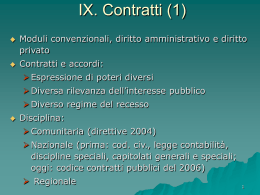
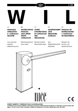
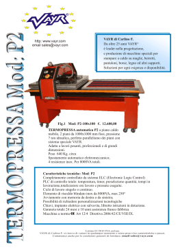
V. 009
METRO
I
GB
F
D
E
MANUALE
ISTRUZIONI
E CATALOGO
RICAMBI
INSTRUCTIONS
MANUAL
AND SPARE
PARTS
CATALOGUE
LIVRET
D’INSTRUCTIONS
ET CATALOGUE
DES
RECHANGES
ANLEITUNGSHEFT
UND
ERSATZTEILKATALOG
MANUAL DE
INSTRUCCIONES
Y CATÁLOGO
DE RECAMBIOS
Attuatore
elettromeccanico
per cancelli a
battente ad una
o due ante.
Electromechanical
actuator for
hinged gates
with one or two
wings.
Actionneur
électromécanique
pour grilles à
battants à une
ou deux portes.
Elektromechanischer
Trieb für ein-und
zweiflügelige
Tore.
Actuador
electromecánico
para cancelas de
batiente de una
o dos hojas.
(Montaggio interrato)
(Underground installation)
(Montage enterré)
(Unterfluymontage)
(Montaje en el terreno)
QUESTO LIBRETTO È DESTINATO SOLO ALL'INSTALLATORE.
L'installazione dovrà essere effettuata solamente da personale professionalmente qualificato in conformità a quanto previsto dalla
legge n° 46 del 5 marzo 1990 e successive modifiche ed integrazioni e nel pieno rispetto delle norme UNI 8612.
METRO
MODELLI E CARATTERISTICHE - MODELS AND CHARACTERISTICS - MODÈLES ET CARACTÉRISTIQUES
MODELLE UND MERKMALE - MODELOS Y CARACTERÍSTICAS
• ME 3000
• ME 3010*
• ME 3024
• ME 3000L
Motoriduttore
I
elettromeccanico
irreversibile, costruito in
alluminio pressofuso, a
tenuta stagna.
Disponibile a 230 V.
c.a. oppure in bassa
tensione.
È bene per un più
duraturo e silenzioso
funzionamento del
motoriduttore,
aggiungere ogni 6 mesi
del grasso nella staffa di
comando tramite
l'apposito ingrassatore
(fig. pag. 4).
Apertura standard
110° (360° con apposito
accessorio opzionale).
Possibilità di sblocco
interno/esterno.
Electromechanical, GB
irreversible, sealed
geared motor made
in die-cast aluminium.
Available with 230 V a.c.
or low voltage.
Every 6 months add
grease to the lubricator
on the control rod of the
gear reducer to ensure
low-noise and troublefree operation
(fig. page 4).
110° standard opening
(360° with a special
optional accessory)
Possibility of inside/
outside unlocking.
Motoréducteur
F
électromécanique
irréversible, construit en
aluminium moulé sous
pression, étanche.
Disponible à 230 V c.a.
ou à basse tension.
Pour assurer un
fonctionament plus
durable et silencieux du
motoréducteur, il est bon
d'ajouter tous les 6 mois
de la graisse dans la
bride de commande à
travers le graisseur
prévu à cet effet (fig.
page 4). Ouverture
standard 110° (360°
avec accessoire spécial
en option). Possibilité de
déblocage de l'intérieur
et de l'extérieur.
Irreversibler,
D
elektromechanischer
Getriebemotor aus
Aludruckguss,
vollkommen dicht. Steht
mit 230 V Wechselstrom
oder mit
Niederspannung zur
Verfügung. Fur einen
dauerhafteren und
leiseren Betrieb des
Getriebemotors sollte
der Steuerbugel alle 6
Monate durch die
vorgesehene Fettbüchse
eingefettet werden
(fig. Ab. 4).
Standardöffnung 110°
(mit speziellem
Sonderzubebör 360°)
Möglichkeit fur inteme
/exteme Entriegelung.
Motorreductor
E
electromecánico
irreversible, fabricado en
aluminio, fundido a
presión, con cierre
hermético.
Disponible en 230 V.
c. a. y también en
baja tensión.
Para un funcionamiento
màs duradero y silencioso
del motorreductor, se
aconseja anadir cada 6
meses grasa en el estribo
de accionamento a través
del respectivo engrasador
(fig. pag. 4).
Apertura estándar 110°
(360° con accesorios
opcionales). Posibilidad de
desbloqueo desde el
interior/exterior.
* A BAGNO D’OLIO
* IN OIL BATH
* EN BAIN D’HUILE
* IN ÖLBAD
* EN BAÑO DE ACEITE
DATI TECNICI - TECHNICAL DATA - DONNEES TECHNIQUES
Unità di misura
Unit of measure
Unité de mesure
Maßeinheit
Unidad de medida
Alimentazione - Power supply - Alimentation
Speisung - Alimentación
2
TECHNISCHE DATEN - DATOS TÉCNICOS
ME 3000 ME 3010 ME 3000L ME 3024
Vac 50 Hz
230
230
230
Vac 50/60 Hz
Vdc
Vdc
-
-
24
Corrente - Current - Courant
Strom - Intensidad
A
1.2
1.2
1.3
5
Potenza assorbita - Absorbed power
Puissance absorbée
AufgenommeneLeistung - Potencia absorbida
W
250
250
300
120
Condensatore incorporato - Condenser built-in
Condensateur incorporé - Kondensator eingebaut
Condensator incorporado
µF
10
10
-
0.8
1.4
10
Velocità - Speed - Vitesse
Geschwindigkeit - Velocidad
Rpm
1.14
1.14
Spinta max. - Maximum thrust
Pousèe maximum - Max. Schub - Empuje max.
Nm
300
300
Temperatura di esecizio - Working temperature
Température de service - Betriebstemperatur
Temperatura de servicio
°C (Min. / Max.)
250
-20° ÷ +70°
250
°C (Min. / Max.)
Termoprotezione - Thermal protection
Protection Thermique - Wärmeschutz
Termoproteccion
°C
140°
140°
140°
-
Ciclo di lavoro - Working cycle
Cycle de travail - Arbeitszyklus
Ciclo de trabajo
%
30
40
30
80
Peso motore - Motor weight - Poids moteur
Motorgewicht - Peso del motor
kg
11
11.5
11
11
METRO
LIMITI DI IMPIEGO - LIMITS OF USE - LIMITES D’UTILISATION - EINSATZGRENZEN - LÍMITES DE EMPLEO
Kg
600
500
Peso massimo anta
Maximum wing weight
Poids
Max Flügelgewicht
Peso màximo de la hoja
Lunghezza massima anta
Maximum wing lenht
Longuer maximum
Max. Flügellänge
Longitud màxima de la hoja
400
300
2,5
I
VERIFICHE
PRELIMINARI
E
A) Leggere attentamente le
istruzioni.
B) Prima di passare
all'installazione, accertarsi
che la struttura del cancello
sia solida ed appropriata.
C) Accertarsi che il cancello,
durante
tutto
il
suo
movimento, non subisca
punti di attrito.
D) Ogni anta deve avere
una
sola
cerniera,
eventualmente eliminare
la
superflua
all'atto
dell'automazione.
E) Prevedere una battuta di
arresto in chiusura e
possibilmente anche in
apertura.
GB
CHECKING
AND PRELIMINARY
PROCEDURES
A) Read the instructions
caretally.
B)
Before
starting
installation, ensure that the
structure of the gate is
sturdy and appropriate.
C) Ensure thet there is no
point of friction during the
entire movement of the gate.
D) Each gate must have just
the one hinge; remove any
other
hinges
upon
automation.
E) Install a stop for closing
and, if possible, one for
opening too.
3
F
CONTRÔLES
PRÉLIMINAIRES
A) Lire attentivement les
instructions.
B) Avant de passer à
l'installation, s’assurer que
la structure de la grille soit
solide et appropriée.
C) S’assurer que la grille
n’ait pas de points de
frottement durant tout le
mouvement.
D) Chaque battant doit
avoir une seule charnière;
éliminer éventuellement la
charnière en pius au
moment de l'automatisation.
E) Prévoir une butée en
fermeture et si possible
aussi en ouverture.
3,5
m
D
PRÜFUNGEN
UND VORBEREITENDE
ARBEITEN
A) Lesen Sie die Anleitungen
aufmerksam durch.
B) Vor der Installation
sicherstellen, daß die Struktur
Ihres Tors solide und für die
Montage geeignet ist.
C) Sicherstellen, daß das
Tor während der gesamten
Bewegug
auf
keine
Reibpunkte trifft.
D) Jeder Flügel darf nur einen
Stützzapfen haben, den
überflüssigen Stützzapfen
gegebenenfalls
bei
der
Automatisierung beseitigen.
E) Einen Endanschlag für das
Schließen und, wenn möglich,
auch für das Öffnen vorsehen.
E
CONTROLES Y
PRELIMINARES
A) Leer atentamente las
instrucciones.
B) Antes de efectuar la
instalación, comprobar que
la estructura de la cancela
sea robusta y adecuada.
C) Comprobar que la
cancela, durante todo su
movimiento, no presente
puntos de roce.
D) Cada puerta debe tener
sólo un gozne, en caso
contrario,
eliminar
el
sobrante en el momento de
la automatización.
E) Tener previsto un tope
para el cierre y, si fuera
posible, también para la
apertura.
QUADRO D' INSIEME - OVERALL PICTURE - CADRE GÉNÉRAL - ÜBERSICHTZEICHNUNG - ESQUEMA DE CONJUNTO
5
4
6
7
9
7
10
2x1
3x1
4x1
2x1
7
3
3x1,5
7
4 x 1,5 **
2x1
4x1
1
2
I
1) Colonnina per
fotocellula.
2) Coppia di arresti in
apertura.
3) Linea 230 V.
4) Quadro di comando
(centralina elettronica)
5) Antenna.
6) Lampeggiatore.
7) Fotocellula.
8) Attuatore METRO.
9) Elettroserratura verticale*
10) Selettore a chiave o
tastiera digitale
* da installare qualora il cancello
superi i mt. 2,5 di lunghezza per
ogni singola anta.
** Mod. 3024 cavo 5x1,5
8
GB
1)
2)
3)
4)
5)
6)
7)
8)
9)
10)
8
F
Column for photocell.
Pair of opening stops.
230 V line.
Control panel (or
electronic control unit).
Aerial.
Flashing light.
Photocell.
METRO actuator.
Vertical electric lock*.
Key selector or
digital keyboard.
* to install if each gate
exceeds 2,5 m in length.
** Mod. 3024 cable 5x1,5
1) Petite colonne pour cellule photo-électrique
2) Couple de butées en
ouverture
3) Ligne à 230V
4) Pupitre de commande
5) Antenne
6) Clignoteur
7) Cellule photo-électrique
8) Actionneur METRO
9) Serrure électrique
verticale*
10) Sélecteur à clé ou
clavier numérique
* à installer si le portail dèpasse
les 2,5 m de longueur pour chaque battant.
* Mod. 3024 cable 5x1,5
D
1)
2)
3)
4)
5)
6)
7)
8)
9)
10)
2
1
E
Säule für Photozelle
Paar Öffnungssperren
Linie 230 V
Schalttafel (oder elektronisches Steuergerät)
Antenne
Blinklicht
Photozelle
METRO-Trieb
Vertikales Elektroschloß*
Schlüsselschalter oder
Digital-Tastatur
* in Tore mit einer Flügellänge
von mehr als 2,5 m einzubauen.
** Mod. 3024 Kabel 5x1,5.
1) Columna para
foto-célula.
2) Par de topes en apertura
3) Línea 230 V
4) Cuadro de mando (o
centralita electrónica)
5) Antena
6) Intermitente
7) Fotocélula
8) Actuator METRO
9) Electrocerradura
vertical *
10) Selector de llave o
teclado digital
* Instalar sólo cuando cada
hoja de las puerta de la verja
supere los 2,5 m. de largo.
** Mod. 3024 Cable 5x1,5
3
METRO
DIMENSIONI D' INGOMBRO - DIMENSIONS - DIMENSIONS D’ENCOMBREMENT - RAUMBEDARF - DIMENSIONES
60
50
142,5
372
306
POSA DELLA
CASSA DI
FONDAZIONE
I
I
1)
2)
3)
4)
5)
6)
7)
8)
GB
Cerniera
Perno
Calcestruzzo
Leva di sblocco
Ingrassatore
Leva di collegamento
Sfera
Leva del riduttore
ATTENZIONE
I
GB
4
LAYING THE
FOUNDATION BOX
GB
1)
2)
3)
4)
5)
6)
7)
8)
Hinge
Pin
Concrete
Unlock lever
Greaser
Connection lever
Ball
Geared motor lever
ATTENTION
POSE DE LA
CAISSE DE
FONDATION
F
F
1)
2)
3)
4)
5)
6)
7)
8)
Charnière
Pivot
Ciment
Levier de déblocage
Graisseur
Levier de raccordement
Sphère
Levier du réducteur
ATTENTION
Togliere i dadi e le rondelle prima di fissare il motoriduttore.
Remove nuts and washers before fixing the gearmotor.
F
Enlever les écrous et les rondelle avant de fixer le motoréducteur.
D
Bevor der Getriebemotor befestigt wird, die Muttern und die
Unterlegscheiben entfernen.
E
Quite las tuercas y arandelas antes de fijar el motorreductor.
VERLEGEN DES
FUNDAMENTKASTENS
D
D
INSTALACION
DE LA CAJA DE
CIMENTACION
E
E
1) Stützzapfen
2) Zapfen
3) Stahlbeton
4) Entriegelungshebel
5) Fettbüchse
6) Verbindungshebel
7) Kugel
8) Getriebemotorhebel
1)
2)
3)
4)
5)
6)
7)
8)
Gozne
Perno
Hormigón
Palanca de desbloqueo
Engrasador
Palanca de conexión
Bola
Palanca del
motorreductor
ACHTUNG
ATENCIÓN
METRO
MEA21
Finecorsa meccanico in chiusura - Mechanical stop for closing manoeuvre - Fin de course mécanique en fermeture - Fin
de carrera mecánico en cierre - Mechanischer Endanshlag in Schließung - Wylacznik graniczny w fazie zamykania
I - Istruzioni di montaggio
GB - Assembly instructions
E - Instrucciones de montaje
F - Instructions de montage
-IVERSIONE 24 Vdc: UTILIZZO OBBLIGATORIO
VERSIONE 230 Vac: UTILIZZO CONSIGLIATO
Non sostituisce la battuta meccanica dell'anta
-FVERSION 24 Vdc: EMPLOI OBLIGATOIRE
VERSION 230 Vac: EMPLOI CONSEILL
Ne remplace pas la butée mécanique du battant
- GB 24 Vdc VERSION: MUST BE USED
230 Vac VERSION: RECOMMENDED USE
It does not replace the leaf's mechanical strike
-D24 Vdc VERSION: PFLICHT
230 VacVERSIONE: EMPFOHLEN
Mechanischer Endanshlag in Schließung
-EVERSIÒN 24 Vdc: USO OBBLIGATORIO
VERSIÒN 230 Vac: USO ACONSEJADO
No sustituye el batiente mecánico de la hoja
- PL WERSJA 24 Vdc: OBOWIAZKOWE ZASTSOWANIE
WERSJA 230 Vac: ZALECANE ZASTOSOWANIE
Nie zastepuje punktu uderzenia mechanicznego skrzydla
D - Montageanweisungen
PL - Instrukje montazu
I
1) Eseguire in base alle dimensioni d'ingombro, uno scavo di fondazione, avendo cura di prevedere un buon drenaggio, in modo da evitare il
ristagno dell'acqua.
2) Collocare la cassa all'interno dello scavo, con il perno allineato alla cerniera del cancello.
3) Prevedere un condotto per i cavi elettrici ed uno per il drenaggio.
4) Annegare nel calcestruzzo la cassa di fondazione, curandone la messa in bolla ed il livello.
5) Inserire sul perno della cassa, la leva di sblocco, avendo cura di interporre la sfera di dotazione.
6) Appoggiare l'anta del cancello sulla leva di sblocco, e fissare con saldatura robusta.
7) Ingrassare mediante apposito ugello ingrassatore.
GB
1)
2)
3)
4)
5)
6)
7)
Keeping overall dimensions in mind, dig a hole for the foundation, making sure it is properly drained to avoid the stagnation of water.
Place the box inside the hole, aligning the pin with the gate's hinge.
Lay one duct for the electric cables and one for drainage.
Bury the foundation box in concrete, making sure it is level.
Mount the unlock lever on the box’s pin, remembering to place the ball provided in between.
Rest the gate against the unlock lever and weld it firmly into place.
Use the greaser nozzle to lubricate.
F
1) Effectuer, suivant les mesures d'encombrement, un trou de fondation en ayant soin de prévoir un drainage efficace de manière à éviter la
stagnation d'eau.
2) Placer la caisse à l'intérieur du trou, avec le pivot dans l'axe de la charnière du portail.
3) Prévoir un conduit pour les câbles électriques et un pour le drainage.
4) Couler le ciment sur la caisse de fondation en veillant à la mettre de niveau.
5) Insérer sur le pivot de la caisse le levier de déblocage en faisant attention à interposer la sphère fournie.
6) Poser la porte du portail sur le levier de déblocage et fixer avec une soudure robuste.
7) Graisser avec un bec graisseur.
D
1)
2)
3)
4)
5)
6)
7)
Je nach Raumbedaff einen Graben für den Fundamentkasten ausheben, dabei eine gute Drainage vorsehen, so dass sich kein Wasser staut.
Den Fundamentkasten im Graben anordnen; der Zapfen muss mit dem Stutzzapfen des Tors ausgerichtet sein.
Eine Leitung fur die Elektrokabel und eine für die Drainage vorsehen.
Den Fundamentkasten einbetonieren, dabei auf die richtige Nivellierung und Höhe achten.
Den Entriegelungshebel auf den Zapfen am Kasten einsetzen und die mitgelieferte Kugel dazwischeniegen.
Den Torflügel auf den Entriegelungshebel stützen und gut anschweissen.
Mit der dazu bestimmten Fettbüchse schmieren.
E
1) Efectuar, de acuerdo con las dimensiones totales, un agujero de cimentación procurando prever un drenaje correcto para evitar que el agua
se estanque.
2) Colocar la caja en el interior del agujero excavado, con el perno alineado al gozne de la verja.
3) Efectuar un canal para pasar los cables eléctricos y otro para el drenaje.
4) Sumergir en el hormigón la caja de cimentación, procurando que quede bien nivelada.
5) Introducir la palanca de desbloqueo en el perno de la caja, procurando intercalar la bola entregada con el equipo.
6) Apoyar la hoja de la puerta de la verja en la palanca de desbloqueo y fijarla con una soldadura resistente.
7) Engrasar utilizando para el lo la boquilla engrasadora.
5
METRO
I
FISSAGGIO
MOTORIDUTTORE
I
GB FIXING THE
GEARED MOTOR
GB
F FIXATION
MOTOREDUCTEUR
F
D BEFESTIGUNG
DES
GETRIEBEMOTORS
D
E SUJECION DEL
MOTORREDUCTOR
E
1) Collocare il moto-riduttore all' interno della cassa e
bloccarlo con viti e rondelle
in dotazione.
1) Position the geared
motor inside the box and fix
it with the screws and
washers provided.
1) Placer le motoréducteur
à l'intérieur de la caisse et
le bloquer avec les vis et
les rondelles fournies.
1) Den Getriebemotor im
Kasten anordnen und mit
den mitgelieferten Schrauben
und
Unterlegscheiben
blockieren.
1) Colocar el motorreductor
en el interior de la caja y
bloquearlo con los tornillos
y las arandelas que se
entregan con el equipo.
2) Collegare la leva del
motoriduttore alla leva di
trascinamento mediante
l'apposita leva di collegamento.
2) Connect the geared
motor's lever to the drive
lever by means of the
connecting lever.
2) Raccorder le levier du
motoréducteur au levier
d'entraînement à l'aide du
levier de raccordement.
2) Mittels des dazu
bestimmten Hebels die
Ve r b i n d u n g
des
Getriebemotorhebels mit
dem Mitnehmerhebel
herstellen.
2) Conectar la palanca del
motorreductor
con
la
palanca
de
arrastre
mediante la correspondiente
palanca de conexión.
I
COLLEGAMENTI
ELETTRICI
Mod. ME 3000
Mod. ME 3010
GB ELECTRIC
CONNECTIONS
Mod. ME 3000
Mod. ME 3010
F BRANCHEMENTS ÉLECTRIQUES
Mod. ME 3000
Mod. ME 3010
D ELEKTROANSCHLÜSSE
Mod. ME 3000
Mod. ME 3010
E CONEXIONES
ELÉCTRICAS
Mod. ME 3000
Mod. ME 3010
I
GB
F
D
E
Nero = Fase "apre"
Black = “open” phase
Noir = Phase “ouvre”
Schwarz = Phase “auf”
Negro = Fase de apertura.
Marrone = Fase "chiude"
Brown = “close” phase
Marron = Phase “ferme”
Braun = Phase “zu”
Marrón = Fase de cierre.
Blu = Comune
Blue = common
Bleu = Commun
Blau = Gemeinsame
Azul = Común.
Giallo/Verde =
Yellow/Green =
Jaune-Vert =
Gelb/Grün =
Amarillo/Verde=
6
METRO
I
COLLEGAMENTI
ELETTRICI
Mod. ME 3024
I
GB ELECTRIC
CONNECTIONS
Mod. ME 3024
GB
F BRANCHEMENTS ÉLECTRIQUES
Mod. ME 3024
F
D ELEKTROANSCHLÜSSE
Mod. ME 3024
D
E CONEXIONES
ELÉCTRICAS
Mod. ME 3024
E
Blu = motore +
Marrone = motore Nero = encoder +
Nero = encoder -
Bleu = engine +
Brown = engine Black = encoder +
Black = encoder -
Bleu = moteur +
Marron = moteur Noir = codeur +
Noir = codeur -
Blau = motor +
Braun = motor Schwarz = encoder +
Schwarz = encoder -
Azul = motor +
Marrón = motor Negro = encoder +
Negro = encoder -
Giallo/Verde =
Yellow/Green =
Jaune/Vert =
Gelb/Grün =
Amarillo/Verde=
I
MANOVRA
MANUALE
GB MANUAL
MANOEUVRE
F MANŒUVRE
MANUELLE
D MANUELLE
BETÄTIGUNG
E MANIOBRA
MANUAL
I
GB
F
D
E
A) Abbassare il coperchio
copriserratura (1) come
indicato.
A) Lower the lock cover
(1) as shown.
A) Abaisser le couvercle de
protection de la serrure (1)
comme l'indique la figure.
A) Den Schlossdeckel (1)
wie gezeigt senken.
A) Bajar la tapa que cubre
la cerradura (1), tal como
se Indica.
B) Inserire la chiave e
ruotarla in senso orario di
90°.
B) Put the key in and turn
it 90° from left to right.
B) Introduire la clé et la
tourner de 90° dans le sens
des aiguilles d'une montre.
B) Den Schlüssel
einstecken und um 90° in
den Uhrzeigersinn drehen.
B) Introducir la llave y
girarla 90° hacia la
derecha.
C) Agire manualmente
sulI'anta.
C) Move the gate
manually.
C) Agir manuellement sur
le battant du portail.
C) Den Torflügel von Hand
betätigen.
C) Mover manualmente la
puerta.
ATTENZIONE:
Il funzionamento
automatico avverrà alla
prima manovra elettrica.
ATTENTION:
It will work automatically
with the first electrical
manoeuvre.
ATTENTION:
Le fonctionnement
automatique aura lieu à
la première manoeuvre
électrique.
ACHTUNG:
Bei der ersten
elektrischen Schaltung
erfolgt der Betrieb auf
automatische Weise.
ATENCION:
El funcionamiento
automático se activará
con la primera maniobra
eléctrica.
7
METRO
I
MONTAGGIO
ELETTROSERRATURA
1)
2)
3)
4)
5)
6)
7)
Elettroserratura.
Piastra di fissaggio elettroserratura.*
Aggancio chiavistello.*
Battuta per aggancio.
Chiavistello.
Barilotto passante.
Cancello.
7
* Specificare se orizzontale o verticale.
2
GB
FITTING THE ELECTRIC
LOCK
1) Electric lock.
2) Plate for fixing the electric lock.*
3) Latch connection.*
4) Connection rabbet.
5) Latch.
6) Through cylinder.
7) Gate.
1
6
3
4
5
* Specify whether horizontal or vertical.
F
MONTAGE DE LA
SERRURE ÉLECTRIQUE
1) Serrure électrique
2) Plaque de fixage de la serrure électrique*
3) Attache du verrou
4) Feuillure pour l’attache
5) Verrou
6) Baricaut passant
7) Grille
- Fissaggio verticale (per due ante)
I
GB - Vertical fastening (for two wings)
F
- Fixage vertical (pour deux portes)
D
- Vertikale Befestigung (für zwei Flügel)
E
- Fijación vertical (para dos hojas)
I
* Préciser si elle est horizontale ou
verticale.
GB - Horizontal fastening (for only one wing)
7
3
D
MONTAGE DES
ELEKTROSCHLOSSES
1) Elektroschloß
2) Anschlagplatte Elektroschloß *
3) Riegelanschlag *
4) Anschlag
5) Riegel
6) durchgehender Zylinder
7) Tor
- Fissaggio orizzontale (per una sola anta)
F
- Fixage horizontal (pour une seule porte)
D
- Horizontale Befestigung (für nur einen Flügel)
E
- Fijación horizontal (para una sola hoja)
2
6
1
* Angeben, ob horizontal oder
vertikal
4
E
MONTAJE DE LA
ELECTROCERRADURA
1) Electrocerradura
2) Placa de fijación de la electrocerradura*
3) Enganche del pestillo*
4) Tope para enganche
5) Pestillo
6) Cilindro pasante
7) Cancela
* Indicar si horizontal o vertical
8
5
METRO
I
ACCESSORI A
RICHIESTA
GB ACCESSORIES
ON REQUEST
F ACCESSOIRES
SUR DEMANDE
D AUF ANFRAGE
ERHÄLTLICHES
ZUBEHÖR
E ACCESORIOS A
PEDIDO
MEA2
I
- Finecorsa meccanico in chiusura.
GB
- Mechanical stop for closing manoeuvre.
F
- Fin de course mécanique en fermeture.
D
- Mechanischer Endanschlag in Schließung.
E
- Fin de carrera mecánico en cierre.
MEA1
I
GB
- Dispositivo per apertura 360°.
- Device for opening 360°.
F
- Dispositif pour ouverture à 360°.
D
- Einrichtung für 360° Öffnung.
E
- Dispositivo para la apertura a 360°.
PLA10
I
GB
- Elettroserratura 12 Vca verticale.
- Vertical 12 Vac electric lock.
F
- Serrure électrique 12 V C A verticale
D
- vertikales Elektroschloß 12 V C A
E
- Electrocerradura 12 V C A vertical.
PLA11
I
GB
- Elettroserratura 12 Vca orizzontale.
- Horizontal 12 Vac electric lock.
F
- Serrure électrique 12 V C A horizontale
D
- Horizontales Elektroschloß 12 V C A
E
- Electrocerradura 12 V C A horizontal.
9
METRO
I
GB
F
D
E
CATALOGO RICAMBI - SPARE PARTS CATALOGUE - CATALOGUE DES RECHANGES - ERSATZTEILKATALOG - CATALOGO DE RECAMBIOS
10
METRO
Nc
CODICI
ME3000
1
2
3
4
5
6
7
8
9
10
11
12
13
14
15
16
17
18
19
20
21
22
23
24
25
26
27
28
29
30
31
32
33
34
35
36
37
38
39
40
41
42
43
44
45
46
47
48
49
50
51
52
53
54
55
56
57
58
59
60
61
62
63
64
65
66
ME3010
ME3024
BMGSML 24567 BMGSML 24567 BMGSML 24567
4567 BMGIM
BMGIM
4567 BMGIM
4567
4567 BMGS
BMGS
4567 BMGS
4567
4610 PMDFC
PMDFC
4610 PMDFC
4610
4610 PMDLP
PMDLP
4610 PMDLP
4610
4610 PMDLA
PMDLA
4610 PMDLA
4610
4610 PMDLF
PMDLF
4610 PMDLF
4610
4610 PMDLC
PMDLC
4610 PMDLC
4610
PMD0573 4610 PMD0573 4610 PMD0573 4610
4610 PMDLU
PMDLU
4610 PMDLU
4610
4610 PMDST
PMDST
4610 PMDST
4610
PMDAP2 4610 PMDAP2 4610 PMDAP2 4610
PMDCO2 4610 PMDCO2 4610 PMDCO2 4610
4610 PMDIP
PMDIP
4610 PMDIP
4610
4610 PMDAU
PMDAU
4610 PMDAU
4610
PMD0039 4610 PMD0039 4610 PMD0039 4610
PPD0788 4540 PPD0788 4540 PPD0788 4540
PMD0793 4610 - PMD0794 4610 - PMD0795 4610
PMD0784 4610 - PMD0785 4610 - PMD0786 4610
PECR50B 4670 PECR50B 4670
///
PEDS501A 4650 PEDS501A 4650
///
///
///
MBA01
0727 10U450
10U450
0727
///
5320 CA
CA
5320 CA
5320
PPD0425 4540 PPD0425 4540 PPD0425 4540
5501 GOR-J
GOR-J
5501 GOR-J
5501
5501 GOR-G
GOR-G
5501 GOR-G
5501
5501 GOR1
GOR1
5501 GOR1
5501
5501 GOR3
GOR3
5501 GOR3
5501
5501 GOR-F
GOR-F
5501 GOR-F
5501
PMCU11 4630 PMCU11 4630 PMCU11 4630
4630 PMCU9
PMCU9
4630 PMCU9
4630
4630 PMCU3
PMCU3
4630 PMCU3
4630
4630 PMCU4
PMCU4
4630
///
2640 MO-G
MO-G
2640 MO-G
2640
2640 MO-H
MO-H
2640 MO-H
2640
2640 MO-C
MO-C
2640 MO-C
2640
4630 PMCS1
PMCS1
4630 PMCS1
4630
5124 16X1
16X1
5124 16X1
5124
1630 CM-D
CM-D
1630 CM-D
1630
MMCT
MPFB3
MP003
MPFB2
PMCS5
PMCS12
///
V10X20A
V4.8X13
V6X8B
V2.9X13A
V6X30B
V4X8
V4.2X13
V8X20B
V4X8-A
V10X35
D10I
D10A
R10C
R10D
R04A
R08B
R12
G6X14
2620
2601
2601
2601
4630
4630
5102
5101
5102
5101
5102
5105
5101
5102
5102
5102
5110
5110
5120
5120
5120
5120
5120
5123
MMCT
MPFB3
MP003
MPFB2
PMCS5
PMCS12
///
V10X20A
V4.8X13
V6X8B
V2.9X13A
V6X30B
V4X8
V4.2X13
V8X20B
V4X8-A
V10X35
D10I
D10A
R10C
R10D
R04A
R08B
R12
G6X14
2620
2601
2601
2601
4630
4630
5102
5101
5102
5101
5102
5105
5101
5102
5102
5102
5110
5110
5120
5120
5120
5120
5120
5123
MMCT
MPFB3
MP003
MPFB2
PMCS5
PMCS12
PPD0234
V10X20A
V4.8X13
V6X8B
V2.9X13A
V6X30B
V4X8
V4.2X13
V8X20B
V4X8-A
V10X35
D10I
D10A
R10C
R10D
R04A
R08B
R12
G6X14
2620
2601
2601
2601
4630
4630
4610
5102
5101
5102
5101
5102
5105
5101
5102
5102
5102
5110
5110
5120
5120
5120
5120
5120
5123
11
Dati cliente / Client data
Nome e cognome ........................................................ Telefono .....................................................................
Name and surname
Telephone
100% papel reciclado
IMPORTANTE / IMPORTANT
Compilare ad installazione avvenuta e trattenere ad uso garanzia.
To be completed after installation and kept for use as a warranty
Matricola .......................................................................
No. Code
Data di installazione .......................................................
Installation date
Termine garanzia ............................................................
Warranty expiry date
Installatore ......................................................................
Installer
Ditta ...............................................................................
Messrs
Indirizzo .........................................................................
Address
Telefono .........................................................................
Telephone
Descrizione materiale installato / Description of the components installed
Centrale di comando
Control box
Radio
Radio
Dispositivi di sicurezza
Safety devices
Note
Notes
papier recycle 100%
Apparecchiatura tipo ......................................................
Appliance type
100% Altpapier
Indirizzo ..................................................................................................................................................................
Address
Date
Date
Date
Date
...................................
...................................
...................................
...................................
Descrizione
Descrizione
Descrizione
Descrizione
/
/
/
/
Description..............................................................................
Description..............................................................................
Description..............................................................................
Description..............................................................................
Da compilare in caso di anomalia (inviare fotocopia della pagina allegandola all’attuatore in riparazione)
To fill in case of defect (send copy of the page enclosed with the actuator to be repaired)
Difetto segnalato / Defect ..........................................................................................................................................
.................................................................................................................................................................................
Parte riservata alla NICE spa per comunicazioni al cliente
Space reserved for NICE spa to communicate with the Clients
Data registrazione ..................................Data riparazione............................... N. Riparazione .............................
Date of registration
Repair date
Repair number
Parti sostituite .......................................................................................................................................................
Parts replaced
Note / Note.......................................................................
Firma tecnico / Technician signature
.........................................................................................
.........................................................................................
.................................................................
carta riciclata 100%
/
/
/
/
Nice SpA
Oderzo TV Italia
Via Pezza Alta, 13 Z.I. Rustignè
Tel. +39.0422.85.38.38
Fax +39.0422.85.35.85
[email protected]
Nice Belgium
Leuven (Heverlee) B
Tel. +32.(0)16.38.69.00
Fax +32.(0)16.38.69.01
[email protected]
Nice España Madrid E
Tel. +34.9.16.16.33.00
Fax +34.9.16.16.30.10
[email protected]
REV. 009
A termini di legge ci riserviamo la proprietà di questo manuale con divieto di riprodurlo o di renderlo comunque noto a terzi
o a ditte concorrenti senza nostra autorizzazione.
Nice France Buchelay F
Tel. +33.(0)1.30.33.95.95
Fax +33.(0)1.30.33.95.96
[email protected]
Nice Polska Pruszków PL
Tel. +48.22.728.33.22
Fax +48.22.728.25.10
[email protected]
www.niceforyou.com
IST ME 4865
Data
Data
Data
Data
recycled paper 100%
Controlli periodici / Periodical check-ups
Scaricare