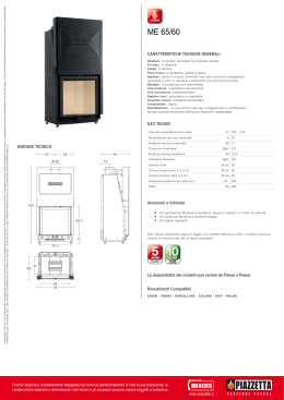
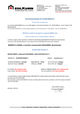
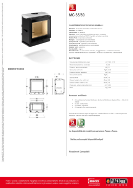
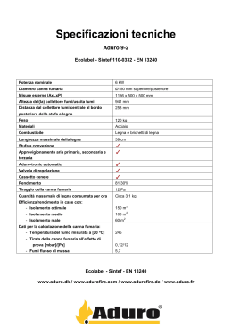
ISTRUZIONI PER L’INSTALLAZIONE, L’USO E LA MANUTENZIONE – IT
INSTRUCTIONS FOR INSTALLATION, USE AND MAINTENANCE - EN
ANWEISUNGEN FÜR DIE AUFSTELLUNG, DEN GEBRAUCH UND DIE WARTUNG - DE
CUCINA A LEGNA / WOOD COOKER / HAUSHALTHERD
AMERICA
Testata secondo / Tested to / Geprüft nach EN 12815
Complimenti per aver acquistato una prodotto a legna LA NORDICA!
Compliments for buying a wood cooker LA NORDICA!
Wir gratulieren Ihnen zum Kauf eines LA NORDICA Holzgerät!
|
•
Sentirsi bene e allo stesso tempo risparmiare energia con i prodotti LA NORDICA diventa possibile!
With LA NORDICA cookers it is now possible to feel good and to save energy at the same time!
Sich wohl fühlen und gleichzeitig Energie sparen: Mit den Produkten der Marke LA NORDICA wird es möglich!
NORME DI SICUREZZA SUGLI APPARECCHI
SAFETY PRESCRIPTIONS ON EQUIPMENT
GERÄTE-SICHERHEITSVORSCHRIFTEN
Secondo le norme di sicurezza sugli apparecchi l’acquirente e l’esercente sono obbligati ad
informarsi sul corretto funzionamento in base alle istruzioni per l’uso.
According to the safety prescriptions on equipment, the purchaser and the operator are obliged
to get informed about the correct operation according to the instructions for use.
Laut der Geräte-Sicherheitsvorschriften sind Käufer und Betreiber verpflichtet, sich über
den funktionsgerechten Betrieb auf Grundlage der Gebrauchanweisung zu informieren.
Cucina a legna / Wood cocker AMERICA
2
Istruzioni per l’uso e la manutenzione / Instructions for use and maintenance – IT – EN – Rev.03
Cucina a legna / Wood cocker AMERICA
INDICE
IT
1.
2.
3.
4.
DATI TECNICI...................................................................................................................................... 5
DESCRIZIONE TECNICA .................................................................................................................... 6
NORME PER L’INSTALLAZIONE ........................................................................................................ 7
SICUREZZA ANTINCENDIO ............................................................................................................... 7
4.1. PRONTO INTERVENTO............................................................................................................... 8
5. CANNA FUMARIA ............................................................................................................................... 9
5.1. POSIZIONE DEL COMIGNOLO.................................................................................................. 10
6. COLLEGAMENTO AL CAMINO ......................................................................................................... 11
7. AFFLUSSO D’ARIA NEL LUOGO D’INSTALLAZIONE DURANTE LA COMBUSTIONE.................... 12
8. COMBUSTIBILI AMMESSI / NON AMMESSI .................................................................................... 12
9. ACCENSIONE ................................................................................................................................... 13
10.
FUNZIONAMENTO NORMALE ...................................................................................................... 14
11.
USO DEL FORNO.......................................................................................................................... 14
12.
FUNZIONE COTTURA ALLA GRIGLIA .......................................................................................... 15
13.
FUNZIONAMENTO NEI PERIODI DI TRANSIZIONE..................................................................... 15
14.
MANUTENZIONE E CURA............................................................................................................. 15
14.1.
PULIZIA CANNA FUMARIA..................................................................................................... 15
14.2.
PULIZIA VETRO...................................................................................................................... 16
14.3.
PULIZIA CASSETTO CENERE ............................................................................................... 16
14.4.
LE MAIOLICHE ....................................................................................................................... 16
15.
FERMO ESTIVO ............................................................................................................................ 16
16.
COLLEGAMENTO ALLA CANNA FUMARIA DI UN CAMINETTO O FOCOLARE APERTO .......... 17
17.
CORRIMANO LATERALI – SIDE HAND-RAILS ASSEMBLY ......................................................... 31
18.
SCHEDA TECNICA – TECHNICAL DATA SHEETS....................................................................... 31
INDEX
EN
TECHNICAL DATA ............................................................................................................................ 18
TECHNICAL DESCRIPTION.............................................................................................................. 19
RULES FOR INSTALLATION ............................................................................................................ 20
FIRE SAFETY.................................................................................................................................... 20
4.1. FIRST-AID MEASURES.............................................................................................................. 21
5. FLUE.................................................................................................................................................. 22
5.1. CHIMNEY CAP POSITION ......................................................................................................... 22
6. CONNECTION TO THE CHIMNEY.................................................................................................... 24
7. AIR ENTRANCE INTO THE INSTALLATION PLACE DURING COMBUSTION................................. 25
8. ADMITTED/NOT ADMITTED FUEL ................................................................................................... 25
9. LIGHTING .......................................................................................................................................... 26
10.
NORMAL OPERATION .................................................................................................................. 27
11.
USE OF THE OVEN ....................................................................................................................... 27
12.
GRILL COOKING ........................................................................................................................... 27
13.
OPERATION IN TRANSITION PERIODS....................................................................................... 28
14.
MAINTENANCE AND CARE .......................................................................................................... 28
14.1.
CLEANING OF THE FLUE ...................................................................................................... 28
14.2.
CLEANING OF THE GLASS ................................................................................................... 29
14.3.
CLEANING OF THE ASH DRAWER ....................................................................................... 29
14.4.
MAJOLICAS ............................................................................................................................ 29
15.
SUMMER STOP............................................................................................................................. 29
16.
CONNECTING A CHIMNEY OR OPEN FURNACE TO THE FLUE................................................ 29
17.
CORRIMANO LATERALI – SIDE HAND-RAILS ASSEMBLY ......................................................... 31
18.
SCHEDA TECNICA – TECHNICAL DATA SHEETS....................................................................... 31
1.
2.
3.
4.
Istruzioni per l’uso e la manutenzione / Instructions for use and maintenance – IT – EN – Rev.03
3
Cucina a legna / Wood cocker AMERICA
DICHIARAZIONE DI CONFORMITA’ DEL COSTRUTTORE
Oggetto: assenza di amianto e cadmio
Si dichiara che tutti i nostri apparecchi vengono assemblati con materiali che non presentano parti di
amianto o suoi derivati e che nel materiale d’apporto utilizzato per le saldature non è presente/utilizzato in
nessuna forma il cadmio, come previsto dalla norma di riferimento.
Oggetto: Regolamento CE n. 1935/2004
Si dichiara che in tutti gli apparecchi da noi prodotti, i materiali destinati a venire a contatto con i cibi sono
adatti all’uso alimentari, in conformità al Regolamento CE in oggetto.
DECLARATION OF CONFORMITY OF THE MANUFACTURER
Object: Absence of asbestos and cadmium
We declare that the materials used for the assembly of all our appliances are without asbestos parts or
asbestos derivates and that in the material used for welding, cadmium is not present, as prescribed in
relevant norm.
Object: CE n. 1935/2004 regulation.
We declare that in all products we produce, the materials which will get in touch with food are suitable for
alimentary use, according to the a.m. CE regulation.
4
Istruzioni per l’uso e la manutenzione / Instructions for use and maintenance – IT – EN – Rev.03
Cucina a legna / Wood cocker AMERICA
Definizione : Cucina a legna secondo EN 12815
1. DATI TECNICI
AMERICA
1
Sistema costruttivo
10
Potenza nominale in kW
Rendimento in %
75.6
CO misurato al 13% di ossigeno in %
0.08
160 SP
Diametro tubo in mm
3.1
Quantità max di combustibile - legna in kg
Emissione gas di scarico in g/s- legna
12.2
Temperatura gas allo scarico in °C - legna
300
Depressione a rendimento calorifico nominale in mmH2O / Pa legna
0,12 / 12
Dimensioni apertura focolare in mm (LxH)
300x405
Dimensioni corpo focolare /piano focolare in mm (LxPxH)
400x410x460
Dimensioni forno in mm (L x H x P)
436x418x430
Tipo di griglia
Griglia piana
880
Altezza stufa in mm
1280
Larghezza stufa in mm
Profondità stufa (senza maniglie) in mm
660
Peso in Kg
321
Capitolo 4
Distanze di sicurezza antincendio
Il volume di riscaldamento delle cucine secondo EN 12815, per edifici il cui isolamento termico non
corrisponde alle disposizioni sulla protezione del calore, è:
(30 Kcal/h x m3) - tipo di costruzione favorevole:
(40 Kcal/h x m3) - tipo di costruzione meno favorevole:
(50 Kcal/h x m3) - tipo di costruzione sfavorevole:
287 m³
215 m³
172 m³
Con un isolamento termico adeguato alle disposizioni sulla protezione del calore il volume di riscaldamento
è maggiore.
Con un riscaldamento temporaneo il volume di riscaldamento diminuisce del 25% circa.
Istruzioni per l’uso e la manutenzione / Instructions for use and maintenance – IT – EN – Rev.03
5
Cucina a legna / Wood cocker AMERICA
2. DESCRIZIONE TECNICA
Le cucine a fuoco continuo de La Nordica si addicono a cucinare sulla piastra e al forno e a riscaldare
spazi abitativi per alcuni periodi, o a sostenere un riscaldamento centralizzato insufficiente. Esse sono
ideali per appartamenti di vacanza e case del fine settimana oppure come riscaldamento ausiliario durante
tutto l’anno. Come combustibili vengono utilizzati ceppi di legna.
La cucina a legna è costituita di lastre in lamiera d’acciaio smaltata e zincata, e fusioni di ghisa smaltata
(porte ,facciata e piastra).
Il focolare è internamente rivestito di singole lastre in ghisa e refrattario (ironker) ed è dotato di aria
terziaria preparata per una migliore combustione. Al suo interno si trova una griglia piana di grosso
spessore regolabile in altezza (Figura 8 Pos.C).
Il focolare è dotato di una porta panoramica con vetro ceramico interno (resistente fino a 700°C) e
temperato esterno. Questo consente un’affascinante vista sulle fiamme ardenti. Inoltre viene così impedita
ogni possibile fuoriuscita di scintille e fumo. Sotto la porta del forno si trova un cassetto estraibile portalegna con relativa porta di chiusura .
Il riscaldamento dell’ambiente avviene:
per irraggiamento: attraverso il vetro panoramico e le superfici esterne calde della stufa viene irraggiato
calore nell’ambiente.
La cucina a legna è fornita di registri d’aria primaria e secondaria, con i quali viene regolata l’aria di
combustione.
D
B
C
A
Figura 1
Registro aria primaria ( pomello inferiore Figura 1 Pos.A)
Con il registro posto nella parte inferiore del cruscotto, viene regolato il passaggio dell’aria primaria nella
parte bassa della cucina attraverso il cassetto cenere e la griglia in direzione del combustibile. L’aria
primaria è necessaria per il processo di combustione. Il cassetto cenere deve essere svuotato
regolarmente, in modo che la cenere non possa ostacolare l’entrata dell’aria primaria necessaria per la
combustione. Attraverso l’aria primaria viene anche mantenuto vivo il fuoco.
Per aprire il passaggio dell’aria bisogna ruotare il pomello in senso antiorario verso SX (ruotare in senso
orario per chiudere verso DX).
Il registro dell’aria primaria deve essere aperto appena un po’ durante la combustione di legna, poiché
altrimenti la legna arde troppo velocemente e la cucina si può surriscaldare (vedi paragrafo 10).
6
Istruzioni per l’uso e la manutenzione / Instructions for use and maintenance – IT – EN – Rev.03
Cucina a legna / Wood cocker AMERICA
Registro aria secondaria ( pomello superiore Figura 1 Pos.B)
Nella parte inferiore del cruscotto si trova il registro dell’aria secondaria. Questo pomello deve essere
aperto (quindi ruotato in senso antiorario verso SX) in particolare per la combustione di legna (vedi
paragrafo 10).
L’aria secondaria, passando attraverso il doppio vetro della porta fuoco, si riscalda ed innesca la doppia
combustione mantenendo nello stesso tempo la pulizia del vetro (con registro aperto).
Registro fumi (Figura 1 Pos.C)
(Conversione dalla funzione di cucina - USO PIASTRA a quella di cucina- USO FORNO cottura al forno e riscaldamento)
Nella parte centrale del cruscotto si trova il registro-fumi, riconoscibile da un pomello smaltato e
contrassegnato.
Quando si posiziona il registro a SX, i gas di combustione fluiscono sopra il forno direttamente verso il
tronchetto di scarico (funzione cucina - USO PIASTRA); quando invece si posiziona a DX, i gas fluiscono
intorno al forno aumentando uniformemente la temperatura al suo interno (funzione cucina-cottura al forno
e riscaldamento - USO FORNO ).
Registro di accensione (Figura 1 Pos.D)
Sulla parte superiore della cucina, tra la piastra smaltata e la facciata, si trova una leva munita di un
pomello cromato. Questa leva serve solamente a facilitare l’accensione della cucina. Quando questa è
totalmente inserita (spinta verso il retro) i fumi fluiscono direttamente verso lo scarico (tubo scarico fumi).
Ad accensione avvenuta, quando la legna inizia a bruciare bene, la leva deve essere totalmente estratta.
3. NORME PER L’INSTALLAZIONE
La cucina è assemblata e pronta per l’allacciamento e deve essere collegata mediante un raccordo
all’esistente canna fumaria della casa. Il raccordo deve essere possibilmente corto, rettilineo, orizzontale o
posizionato leggermente in salita. I collegamenti devono essere a tenuta stagna. E’ obbligatorio
rispettare norme nazionali ed europee, disposizioni locali o in materia di legislazione edilizia,
nonché regolamentazioni antincendio. Pertanto vi consigliamo di informarvi preventivamente presso il
Vs. capo spazzacamino distrettuale.
Bisogna inoltre verificare il sufficiente afflusso d’aria necessario alla combustione, a tale proposito è
fondamentale prestare attenzione a finestre e porte con chiusura stagna (guarnizioni di tenuta).
Non è consentito il collegamento di più apparecchi allo stesso camino. Il diametro dell’apertura della canna
fumaria per il collegamento deve corrispondere per lo meno al diametro del tubo fumo.
L’apertura dovrebbe essere dotata di una connessione a muro per la ricezione del tubo di scarico e di un
rosone. Il foro di uscita fumi non utilizzato deve essere ricoperto con il relativo tappo.
Prima dell’installazione verificare se la portata della sottostruttura regge il peso del vostro apparecchio. In
caso di portata insufficiente è necessario adottare opportune misure (ad es. piastra per la distribuzione del
peso ).
La Nordica S.p.a. non è responsabile del prodotto modificato senza autorizzazione e tanto meno
per l’uso di ricambi non originali.
I focolari non si devono modificare !
4. SICUREZZA ANTINCENDIO
Nell’installazione della cucina devono essere osservate le seguenti misure di sicurezza:
a) la distanza minima da elementi costruttivi ed oggetti infiammabili e sensibili al calore (mobili,
rivestimenti di legno, stoffe ecc.) deve essere di 20 cm dal retro e da entrambi i lati; al fine di
assicurare un sufficiente isolamento termico (Figura 2 pos.A).
b) davanti alla porta del focolare e nell’area di radiazione della stessa non deve esserci alcun oggetto
o materiale di costruzione infiammabile e sensibile al calore a meno di 100 cm di distanza.Tale
distanza può essere ridotta a 40 cm qualora tra il focolare e gli elementi costruttivi infiammabili si
installi una lamiera di protezione areata su entrambi i lati. Tutte le distanze minime di sicurezza
sono indicate sulla targhetta del prodotto e si devono rispettare tassativamente.
Istruzioni per l’uso e la manutenzione / Instructions for use and maintenance – IT – EN – Rev.03
7
Cucina a legna / Wood cocker AMERICA
c) qualora la cucina venga installata su un pavimento di materiale infiammabile, bisogna prevedere un
sottofondo ignifugo, per esempio una pedana d'acciaio (dimensioni secondo l’ordinamento
regionale).
Il rivestimento deve sporgere frontalmente di almeno 50 cm e lateralmente di almeno 30 cm oltre
all’apertura della porta di carico (Figura 2 pos.B).
La cucina deve funzionare esclusivamente con il cassetto cenere inserito. I residui solidi della combustione
(ceneri) devono essere raccolti in un contenitore ermetico e resistente al fuoco. La cucina non deve mai
essere accesa in presenza di emissioni gassose o vapori (per esempio colla per linoleum, benzina ecc.).
Non depositate materiali infiammabili nelle vicinanze della cucina.
Durante la combustione viene sprigionata energia termica che comporta un marcato riscaldamento delle
superfici, di porte, maniglie, comandi, vetri, tubo fumi ed eventualmente della parte anteriore
dell’apparecchio. Evitare il contatto con tali elementi senza un corrispondente abbigliamento protettivo o
senza utensili accessori (guanti resistenti al calore, dispositivi di comando). Fate in modo che i bambini
siano consapevoli di questi pericoli e teneteli lontani dal focolare durante il suo funzionamento.
Quando si utilizza un combustibile errato o troppo umido , a causa di depositi presenti nella canna fumaria
si potrebbe avere un incendio della stessa.
A
B
Figura 2
4.1.
PRONTO INTERVENTO
Se si manifesta un incendio nel collegamento o nella canna fumaria :
a) Chiudere la porta di caricamento e del cassetto cenere.
b) Chiudere i registri dell’aria comburente
c) Spegnere tramite l’uso di estintori ad anidride carbonica ( CO2 a polveri )
d) Richiedere l’immediato intervento dei Vigili del Fuoco
Non spegnere il fuoco con l’uso di getti d’acqua.
Quando la canna fumaria smette di bruciare farla verificare da uno specialista per individuare eventuali
crepe o punti permeabili.
8
Istruzioni per l’uso e la manutenzione / Instructions for use and maintenance – IT – EN – Rev.03
Cucina a legna / Wood cocker AMERICA
5. CANNA FUMARIA
Requisiti fondamentali per un corretto funzionamento dell’apparecchio:
• la sezione interna deve essere preferibilmente circolare;
•
essere termicamente isolata ed impermeabile e costruita con materiali idonei a resistere al calore,
ai prodotti della combustione ed alle eventuali condense;
•
essere priva di strozzature ed avere andamento verticale con deviazioni non superiori a 45°;
•
se già usata deve essere pulita;
•
rispettare i dati tecnici del manuale di istruzioni;
Qualora le canne fumarie fossero a sezione quadrata o
rettangolare gli spigoli interni devono essere arrotondati
con raggio non inferiore a 20 mm. Per la sezione
rettangolare il rapporto massimo tra i lati deve essere ≤
1,5.
Una sezione troppo piccola provoca una diminuzione del
tiraggio. Si consiglia un’altezza minima di 4 m.
Sono vietate e pertanto pregiudicano il buon
funzionamento dell’apparecchio: fibrocemento, acciaio
zincato, superfici interne ruvide e porose. In Figura 3
sono riportati alcuni esempi di soluzione.
La sezione minima deve essere di 4 dm2 (per esempio
20x20cm) per gli apparecchi il cui diametro di
condotto è inferiore a 200mm, o 6,25dm2 (per esempio
25x25cm) per gli apparecchi con diametro superiore a
200mm.
Il tiraggio creato dalla vostra canna fumaria deve essere
sufficiente ma non eccessivo.
Una sezione della canna fumaria troppo importante può
presentare un volume troppo grande da riscaldare e
dunque provocare delle difficoltà di funzionamento
dell’apparecchio; per evitare ciò provvedete ad intubare la
stessa per tutta la sua altezza. Una sezione troppo
piccola provoca una diminuzione del tiraggio.
(1)
(2)
(3)
(4)
A+1/2A
Max.
A+1/2A
A
(1) Canna fumaria in acciaio AISI 316 con doppia
camera isolata con materiale resistente a
400°C. Efficienza 100% ottima.
(2) Canna fumaria in refrattario con doppia
camera isolata e rivestimento esterno in
calcestruzzo alleggerito. Efficienza 100%
ottima.
(3) Canna fumaria tradizionale in argilla sezione
quadrata con intercapedini. Efficienza 80%
ottima.
(4) Evitare canne fumarie con sezione
rettangolare interna il cui rapporto sia diverso
dal disegno.
Efficienza 40% mediocre.
Figura 3
La canna fumaria deve essere adeguatamente distanziata da materiali infiammabili o combustibili
mediante un opportuno isolamento o un’intercapedine d’aria.
E’ vietato far transitare all’interno della stessa tubazioni di impianti o canali di adduzione d’aria. E’ proibito
inoltre praticare aperture mobili o fisse, sulla stessa, per il collegamento di ulteriori apparecchi diversi.
(1) Comignolo industriale
ad elementi prefabbricati,
consente
un
ottimo
smaltimento dei fumi.
(2) Comignolo artigianale.
La giusta sezione di uscita
deve essere minimo 2 volte
la sezione interna della
canna fumaria, ideale 2,5
volte.
(3) Comignolo per canna
fumaria in acciaio con
cono interno deflettore
dei fumi.
Fig. 4
Istruzioni per l’uso e la manutenzione / Instructions for use and maintenance – IT – EN – Rev.03
9
Cucina a legna / Wood cocker AMERICA
5.1.
POSIZIONE DEL COMIGNOLO
Il tiraggio della canna fumaria dipende anche dall’idoneità del comignolo.
È pertanto indispensabile che, se costruito artigianalmente, la sezione di uscita sia più di due volte la
sezione interna della canna fumaria.
Dovendo sempre superare il colmo del tetto, il comignolo dovrà assicurare lo scarico anche in presenza di
vento (Fig. 4).
Il comignolo deve rispondere ai seguenti requisiti:
• avere sezione interna equivalente a quella del camino.
• avere sezione utile d’uscita doppia di quella interna della canna fumaria.
• essere costruito in modo da impedire la penetrazione nella canna fumaria di pioggia, neve e di
qualsiasi corpo estraneo.
• essere facilmente ispezionabile, per eventuali operazioni di manutenzione e pulizia.
50 cm
(1) In caso di canne fumarie affiancate un
comignolo dovrà sovrastare l’altro d’almeno 50 cm
al fine d’evitare trasferimenti di pressione tra le
canne stesse.
Fig. 5
2m
10 m
(1) Il comignolo non deve avere ostacoli entro i 10 m da muri,
falde ed alberi. In caso contrario innalzare lo stesso d’almeno
1 m sopra l’ostacolo.
Il comignolo deve oltrepassare il colmo del tetto d’almeno 1 m.
1
m
Figura 6
>A
>
_A
0,5 m
H min.
(1)Asse colmo
α
(2)Tetto
Figura 7
10
Istruzioni per l’uso e la manutenzione / Instructions for use and maintenance – IT – EN – Rev.03
Cucina a legna / Wood cocker AMERICA
COMIGNOLI DISTANZE E POSIZIONAMENTO UNI 10683/98
Inclinazione del tetto
Distanza tra il colmo e il camino
Altezza minima del camino (misurata dallo
sbocco)
α
A (m)
H (m)
< 1,85 m
0,50 m oltre il colmo
> 1,85 m
1,00 m dal tetto
< 1,50 m
0,50 m oltre il colmo
> 1,50 m
1,30 m dal tetto
< 1,30 m
0,50 m oltre il colmo
> 1,30 m
2,00 m dal tetto
< 1,20 m
0,50 m oltre il colmo
> 1,20 m
2,60 m dal tetto
15°
30°
45°
60°
6.
COLLEGAMENTO AL CAMINO
Le cucine con chiusura automatica (tipo 1) della porta devono obbligatoriamente funzionare, per motivi di
sicurezza, con la porta del focolare chiusa (fatta eccezione per la fase di carico del combustibile o
l’eventuale rimozione della cenere).
Le cucine con le porte non a chiusura automatica (tipo 2) devono essere collegate ad una propria canna
fumaria .
Il funzionamento con porta aperta è consentito soltanto previa sorveglianza.
Il tubo di collegamento alla canna fumaria deve essere più corto possibile, rettilineo ed a tenuta stagna.
Il collegamento deve essere eseguito con tubi stabili e robusti (Vi consigliamo uno spessore di 2 mm) ed
essere fissato ermeticamente alla canna fumaria. Il diametro interno del tubo di collegamento deve
corrispondere al diametro esterno del tronchetto di scarico fumi della cucina (DIN 1298).
ATTENZIONE: qualora il collegamento attraversi particolari composti da materiali infiammabili, nel raggio
di 20cm attorno al tubo tutti i materiali infiammabili devono essere sostituiti da materiali ignifughi e
resistenti al calore.
Per un buon funzionamento dell’apparecchio è essenziale che nel luogo d’installazione venga immessa
sufficiente aria per la combustione (vedi paragrafo 10).
La depressione al camino dovrebbe essere 12 Pa (=1,2 mm di colonna d’acqua). La misurazione deve
essere fatta sempre ad apparecchio caldo (resa calorifica nominale). Quando la depressione supera 17 PA
(1,7mm di colonna d’acqua) è necessario ridurla con l’installazione di un regolatore di tiraggio
supplementare (valvola a farfalla) sul tubo di scarico o nel camino.
Istruzioni per l’uso e la manutenzione / Instructions for use and maintenance – IT – EN – Rev.03
11
Cucina a legna / Wood cocker AMERICA
7. AFFLUSSO D’ARIA NEL LUOGO D’INSTALLAZIONE DURANTE LA
COMBUSTIONE
Poiché le cucine ricavano la loro aria di combustione dal locale di installazione, è essenziale che nel luogo
stesso venga immessa una sufficiente quantità d’aria. In caso di finestre e porte a tenuta stagna (es .case
costruite con il criterio di risparmio energetico) è possibile che l’ingresso di aria fresca non venga più
garantito e questo compromette il tiraggio dell’apparecchio, il vostro benessere e la vostra sicurezza.
Bisogna pertanto garantire una alimentazione aggiuntiva di aria fresca mediante una presa d’aria esterna
posta nelle vicinanze dell’apparecchio oppure tramite la posa di una conduttura per l’aria di combustione
che porti verso l’esterno od in un vicino locale areato, ad eccezione del locale caldaia o garage
(VIETATO).
Il tubo di collegamento deve essere liscio con un diametro minimo di 120 mm, deve avere una lunghezza
massima di 4 m e presentare non più di tre curve. Qualora questo sia collegato direttamente con l’esterno
deve essere dotato di un apposito frangivento.
L’entrata dell’aria per la combustione nel luogo d’installazione non deve essere ostruita durante il
funzionamento della cucina. E’ assolutamente necessario che negli ambienti, in cui vengono fatte
funzionare cucine con un tiraggio naturale del camino, venga immessa tanta aria quanta ne è necessaria
per la combustione, ossia fino a 20 m³/ora. Il naturale ricircolo dell’aria deve essere garantito da alcune
aperture fisse verso l’esterno, la loro grandezza è stabilita da relative normative in materia. Chiedete
informazioni al Vostro spazzacamino di fiducia. Le aperture devono essere protette con delle griglie e non
devono mai essere otturate. Una cappa di estrazione (aspirante) installata nella stessa stanza od in una
confinante provoca una depressione nell’ambiente. Questo provoca la fuoriuscita di gas combusti (fumo
denso, odore); é dunque necessario assicurare un maggiore afflusso di aria fresca.
La depressione di una cappa aspirante può, nella peggiore delle ipotesi, trasformare la canna
fumaria della cucina in presa d’aria esterna risucchiando i fumi nell’ambiente con conseguenze
gravissime per le persone.
8. COMBUSTIBILI AMMESSI / NON AMMESSI
I combustibili ammessi sono ceppi di legna da ardere. Si devono utilizzare esclusivamente ceppi di legna
secca (contenuto d’acqua max 20%).
I pezzi di legna dovrebbero avere una lunghezza di ca. 30cm ed una circonferenza di 30-35 cm max.
Kg/mc
KWh/Kg
Umidità 20%
Faggio
750
4,0
Cerro
900
4,2
Olmo
640
4,1
Pioppo
470
4,1
Larice *
660
4,4
Abete rosso *
450
4,5
Pino silvestre *
550
4,4
Specie
* LEGNI RESINOSI POCO ADATTI PER UNA STUFA
La legna usata come combustibile deve avere un contenuto d’umidità inferiore al 20% e la si ottiene con un
tempo di essiccazione di almeno un anno (legno tenero) o di due anni (legno duro) in ambiente asciutto e
ventilato (per esempio sotto una tettoia). La legna umida rende l’accensione più difficile, poiché è
necessaria una maggiore quantità d’energia per far evaporare l’acqua presente.
12
Istruzioni per l’uso e la manutenzione / Instructions for use and maintenance – IT – EN – Rev.03
Cucina a legna / Wood cocker AMERICA
Il contenuto umido ha inoltre lo svantaggio che, con l’abbassarsi della temperatura, l’acqua si condensa
prima nel focolare e quindi nel camino. La legna fresca contiene circa il 60% di H2O, perciò non è adatta
ad essere bruciata.
Tra gli altri non possono essere bruciati: resti di carbone, ritagli, cascami di corteccia e pannelli,
legna umida o trattata con vernici, materiali di plastica; in tal caso decade la garanzia
sull’apparecchio.
Carta e cartone devono essere utilizzati solo per l’accensione. La combustione di rifiuti è vietata e
danneggerebbe la stufa e la canna fumaria, provocando inoltre danni alla salute ed in virtù del disturbo
olfattivo a reclami da parte del vicinato.
La legna non è un combustibile a lunga durata e pertanto non è possibile un riscaldamento continuo della
cucina durante la notte.
ATTENZIONE: L'uso continuo e prolungato di legna particolarmente ricca di oli aromatici (p.e.
Eucalipto, Mirto, etc.) provoca il deterioramento (sfaldamento) repentino dei componenti in ghisa
presenti nel prodotto.
9. ACCENSIONE
IMPORTANTE: alla prima accensione è inevitabile che venga prodotto un odore sgradevole (dovuto
all’essiccamento dei collanti nella cordicella d i guarnizione o delle vernici protettive), che sparisce
dopo un breve utilizzo. Deve comunque essere assicurata una buona ventilazione dell’ambiente. Alla
prima accensione Vi consigliamo di caricare una quantità ridotta di combustibile e di aumentare
lentamente la resa calorifica dell’apparecchio.
Per effettuare una corretta prima accensione dei prodotti trattati con vernici per alte temperature, occorre
sapere quanto segue:
• i materiali di costruzione dei prodotti in questione non sono omogenei, infatti coesistono parti in
ghisa, in acciaio, in refrattario e in maiolica;
• la temperatura alla quale il corpo del prodotto è sottoposto non è omogenea: da zona a zona si
registrano temperature variabili dai 300°C ai 500°C ;
• durante la sua vita, il prodotto è sottoposto a cicli alternati di accensioni e di spegnimento durante la
stessa giornata e a cicli di intenso utilizzo o di assoluto riposo al variare delle stagioni;
• la cucina nuova, prima di potersi definire stagionata, dovrà essere sottoposta a diversi cicli di
avviamento per poter consentire a tutti i materiali ed alla vernice di completare le varie sollecitazioni
elastiche;
• in particolare inizialmente si potrà notare l’emissione di odori tipici dei metalli sottoposti a grande
sollecitazione termica e di vernice ancora fresca. Tale vernice, sebbene in fase di costruzione
venga cotta a 250°C per qualche ora, dovrà superare più volte e per una certa durata la
temperatura di 350°C, prima di incorporarsi perfett amente con le superfici metalliche.
Diventa quindi importante seguire questi piccoli accorgimenti in fase di accensione:
1. Assicuratevi che sia garantito un forte ricambio d'aria nel luogo dove è installato l'apparecchio.
2. Nelle prime accensioni, caricare non eccessivamente la camera di combustione (circa metà della
quantità indicata nel manuale d'istruzioni) e tenere il prodotto acceso per almeno 6-10 ore di
continuo, con i registri meno aperti di quanto indicato nel manuale d'istruzioni.
3. Ripetere questa operazione per almeno 4-5 o più volte, secondo la Vostra disponibilità.
4. Successivamente caricare sempre più (seguendo comunque quanto descritto sul libretto di
istruzione relativamente al massimo carico) e tenere possibilmente lunghi i periodi di accensione
evitando, almeno in questa fase iniziale, cicli di accensione-spegnimento di breve durata.
5. Durante le prime accessioni nessun oggetto dovrebbe essere appoggiato sulla cucina ed in
particolare sulle superfici laccate. Le superfici laccate non devono essere toccate durante il
riscaldamento.
6. Una volta superato il "rodaggio" si potrà utilizzare il Vostro prodotto come il motore di un’auto,
evitando bruschi riscaldamenti con eccessivi carichi.
Per accendere il fuoco consigliamo di usare piccoli listelli di legno con carta di giornale oppure altri mezzi di
accensione in commercio, escluse tutte le sostanze liquide come per es. alcool, benzina, petrolio e simili.
Le aperture per l’aria (primaria e secondaria) devono essere aperte insieme, il registro di accensione (D)
deve essere aperto, ovvero la leva di comando deve essere spinta verso la schiena, mentre il pomello
Istruzioni per l’uso e la manutenzione / Instructions for use and maintenance – IT – EN – Rev.03
13
Cucina a legna / Wood cocker AMERICA
centrale (C) deve essere ruotato a SX (si deve aprire anche l’eventuale valvola a farfalla posta sul tubo di
scarico fumi).
Quando la legna comincia ad ardere si possono caricare altri combustibili; chiudere il registro (D) tirando la
leva e regolare l’aria per la combustione secondo le indicazioni del paragrafo 10. Durante questa fase non
lasciare mai la cucina senza supervisione.
Non si deve mai sovraccaricare la cucina (confrontare la tabella dati tecnici – quantità max di
combustibile caricabile).
Troppo combustibile e troppa aria per la combustione possono causare surriscaldamento e quindi
danneggiare la cucina. La garanzia non copre i danni dovuti al surriscaldamento dell’apparecchio.
10. FUNZIONAMENTO NORMALE
Gli apparecchi con chiusura automatica della porta (tipo 1) devono obbligatoriamente funzionare, per
motivi di sicurezza, con la porta del focolare chiusa (fatta eccezione per la fase di carico del combustibile o
l’eventuale rimozione della cenere ).
Gli apparecchi con le porte non a chiusura automatica (tipo 2) devono essere collegati ad una propria
canna fumaria. Il funzionamento con porta aperta è consentito soltanto previa sorveglianza.
IMPORTANTE: Per motivi di sicurezza la porta del focolare può essere aperta solo durante il
caricamento di combustibile. Il focolare deve rimanere chiuso durante il funzionamento ed i periodi
di non-utilizzo.
Il potere calorifico nominale della cucina viene raggiunto con un tiraggio (depressione) minimo di 10-12 Pa
( =1 – 1,2 mm di colonna d’acqua ).
Con i registri posti sulla facciata della cucina (Figura 1) viene regolata l’emissione di calore del focolare.
Essi devono essere aperti secondo il bisogno calorifico.
La migliore combustione (emissioni minime) viene raggiunta quando, caricando legna, la maggior parte
dell’aria per la combustione passa attraverso il registro aria secondaria.
Bisogna pertanto usare la cucina sempre con porta chiusa per evitare l’effetto forgia.
Non si deve mai sovraccaricare la cucina. Troppo combustibile e troppa aria per la combustione
possono causare surriscaldamento e quindi danneggiare la cucina. I danni causati da
surriscaldamento non sono coperti da garanzia.
COMBUSTIBILE
ARIA PRIMARIA
(POMELLO INFERIORE)
ARIA SECONDARIA
(POMELLO SUPERIORE)
LEGNA
CHIUSO
APERTO
La leva del registro di accensione (D) deve essere CHIUSA e cioè totalmente estratta.
L’intensità della combustione e quindi la resa calorifica della Vostra cucina è influenzata dal camino. Un
buon tiraggio del camino richiede una regolazione minore quantità d’aria per la combustione, mentre uno
scarso tiraggio necessita di una maggiore quantità.
IMPORTANTE : per verificare la buona combustione della stufa, verificate che il fumo che esce dal camino
sia trasparente. Se è bianco significa che la cucina non è regolata correttamente o la legna è troppo
bagnata; se invece il fumo è grigio o nero è segno che la combustione non è completa (è necessaria una
maggior quantità di aria secondaria).
11. USO DEL FORNO
Dopo aver pulito la griglia del focolare caricate del combustibile. Grazie all’apporto d’aria per la
combustione la temperatura del forno può essere sensibilmente influenzata. Un sufficiente tiraggio al
camino e dei canali ben puliti per il flusso dei fumi roventi attorno al forno sono fondamentali per un buon
risultato di cottura. Il registro dei fumi deve essere tirato completamente verso l’esterno.
14
Istruzioni per l’uso e la manutenzione / Instructions for use and maintenance – IT – EN – Rev.03
Cucina a legna / Wood cocker AMERICA
La padella forno può essere collocata su diversi piani. Torte spesse e arrosti grandi sono da inserire al
livello più basso. Torte piatte e biscotti vanno al livello medio. Il livello superiore può essere utilizzato per
riscaldare o rosolare.
12. FUNZIONE COTTURA ALLA GRIGLIA
Con la cucina America è possibile effettuare la cottura dei
cibi alla griglia. Una volta pronte le braci, bisogna tenere
aperta la porta del focolare, posizionate il riparo in
lamiera (CAPPA ESTERNA Figura 8 Pos.A) come
mostrato in figura e sistemate la griglia di cottura
(GRIGLIANDOLA Pos.B) all’interno del focolare.
I registri vanno posizionanti nel seguente modo:
A
B
- registro aria primaria e aria secondaria (Figura 1 A,B)
chiusi e cioè ruotati in senso orario DX
- registro fumi (Figura 1 C) ruotato verso SX
- registro di accensione (Figura 1 D) totalmente inserito
(spinto verso il retro della cucina)
Figura 8
C
13. FUNZIONAMENTO NEI PERIODI DI TRANSIZIONE
Durante il periodo di transizione, quando le temperature esterne sono più elevate, si possono avere dei
disturbi alla canna fumaria che fanno si che i gas combusti non vengano aspirati completamente. I gas di
scarico non fuoriescono più completamente (odore intenso di gas).
In tal caso scuotete più frequentemente la griglia e aumentate l’aria per la combustione. Caricate in seguito
una quantità ridotta di combustibile facendo sì che questo bruci più rapidamente (con sviluppo di fiamme) e
si stabilizzi così il tiraggio della canna fumaria. Controllate quindi che tutte le aperture per la pulizia e i
collegamenti al camino siano ermetici.
14. MANUTENZIONE E CURA
Fate controllare dal Vostro spazzacamino responsabile di zona la regolare installazione della cucina, il
collegamento al camino e l’aerazione.
Per la pulizia delle parti smaltate usare acqua saponata o detergenti non abrasivi o chimicamente
aggressivi.
Qualora i componenti cromati dovessero diventare azzurrognoli a causa di un surriscaldamento, ciò può
essere risolto con un adeguato prodotto per la pulizia.
IMPORTANTE : si possono usare esclusivamente parti di ricambio espressamente autorizzate ed offerte
da La Nordica. In caso di bisogno Vi preghiamo di rivolgerVi al Vs rivenditore specializzato.
L’ apparecchio non può essere modificato!
14.1.
PULIZIA CANNA FUMARIA
La corretta procedura di accensione, l’utilizzo di quantità e tipi di combustibili idonei, il corretto
posizionamento del registro dell’aria secondaria, il sufficiente tiraggio del camino e la presenza d’aria
comburente sono indispensabili per il funzionamento ottimale dell’apparecchio. Almeno una volta l’anno è
consigliabile eseguire una pulizia completa, o qualora sia necessario (problemi di malfunzionamento con
scarsa resa). Questa operazione, fatta esclusivamente a cucina fredda, dovrebbe essere svolta da
uno spazzacamino che contemporaneamente può effettuare un’ispezione.
Istruzioni per l’uso e la manutenzione / Instructions for use and maintenance – IT – EN – Rev.03
15
Cucina a legna / Wood cocker AMERICA
Durante la pulizia bisogna togliere dalla cucina il tronchetto di scarico-fumi e il tubo-fumi.
Il vano di raccolta dei fumi può essere pulito attraverso lo sportello posto sotto il forno (dopo aver tolto le
due viti che fissano lo stesso alla facciata della cucina), oppure dall’alto.
A tale scopo rimuovete i cerchi della piastra di cottura e smontate il tubo-fumi dal tronchetto di scarico. La
pulizia può essere effettuata con l’aiuto di una spazzola e di un aspiratore.
Fate attenzione che dopo la pulizia tutte le parti smontate vengano reinstallate in modo ermetico.
14.2.
PULIZIA VETRO
Tramite uno specifico ingresso dell’aria secondaria la formazione di deposito di sporco, sul vetro della
porta, viene efficacemente rallentata. Non può comunque mai essere evitata con l’utilizzo dei combustibili
solidi (es. legna umida ) e questo non è da considerarsi come un difetto dell’apparecchio .
IMPORTANTE: la pulizia del vetro panoramico deve essere eseguita solo ed esclusivamente a
cucina fredda per evitarne l’esplosione. Non usare comunque panni, prodotti abrasivi o chimicamente
aggressivi.
ROTTURA DEI VETRI: i vetri essendo in vetroceramica resistenti fino ad uno sbalzo termico di
750°C, non sono soggetti a shock termici. La loro r ottura può essere causata solo da shock
meccanici (urti o chiusura violenta della porta ecc.). Pertanto la sostituzione non è in garanzia .
14.3.
PULIZIA CASSETTO CENERE
Tutte le stufe-camino e cucine LA NORDICA hanno una griglia focolare con relativo scuoti-griglia ed un
cassetto per la raccolta della ceneri. Vi consigliamo di svuotare periodicamente il cassetto cenere e di
evitarne il riempimento totale, per non surriscaldare la griglia. Inoltre Vi consigliamo di lasciare sempre 3-4
cm di cenere nel focolare.
ATTENZIONE: le ceneri tolte dal focolare vanno riposte in un recipiente di materiale ignifugo dotato di un
coperchio stagno. Il recipiente va posto su di un pavimento ignifugo, lontano da materiali infiammabili fino
allo spegnimento e raffreddamento completo delle ceneri.
14.4.
LE MAIOLICHE
Le maioliche La NORDICA sono prodotti di alta fattura artigianale e come tali possono presentare micropuntinature, cavillature ed imperfezioni cromatiche. Queste caratteristiche ne testimoniano la pregiata
natura.
Smalto e maiolica, per il loro diverso coefficiente di dilatazione, producono microscrepolature (cavillatura)
che ne dimostrano l’effettiva autenticità.
Per la pulizia delle maioliche si consiglia di usare un panno morbido ed asciutto; se si usa un qualsiasi
detergente o liquido, quest’ultimo potrebbe penetrare all’interno dei cavilli evidenziando gli stessi.
15. FERMO ESTIVO
Dopo aver effettuato la pulizia del focolare, del camino e della canna fumaria, provvedendo all’eliminazione
totale della cenere ed altri eventuali residui, chiudere tutte le porte del focolare ed i relativi registri e
sconnettere l’apparecchio dal camino.
Consigliamo di effettuare l’operazione di pulizia della canna fumaria almeno una volta all’anno; verificare
nel frattempo l’effettivo stato delle guarnizioni che, se non perfettamente integre, non garantiscono il buon
funzionamento dell’apparecchio!
In tal caso è necessaria la sostituzione delle stesse.
In caso di umidità del locale dove è posto l’apparecchio, sistemare dei sali assorbenti all’interno del
focolare.
Proteggere le parti in ghisa grezze, se si vuole mantenere inalterato nel tempo l’aspetto estetico, con della
vaselina neutra.
16
Istruzioni per l’uso e la manutenzione / Instructions for use and maintenance – IT – EN – Rev.03
Cucina a legna / Wood cocker AMERICA
16. COLLEGAMENTO ALLA CANNA FUMARIA DI UN CAMINETTO O
FOCOLARE APERTO
Il canale fumi è il tratto di tubo che collega il prodotto alla canna fumaria, nel collegamento devono essere
rispettati questi semplici ma importantissimi principi:
•
•
•
•
•
per nessuna ragione si dovrà usare il canale fumo avente un diametro inferiore a quello del
collarino di uscita di cui è dotato il prodotto;
ogni metro di percorso orizzontale del canale fumo provoca una sensibile perdita di carico che
dovrà eventualmente essere compensata con un innalzamento della canna fumaria;
il tratto orizzontale non dovrà comunque mai superare i 2m (UNI 10683-2005);
ogni curva del canale fumi riduce sensibilmente il tiraggio della canna fumaria che dovrà essere
eventualmente compensata innalzandola adeguatamente;
la Normativa UNI 10683-2005 – ITALIA prevede che le curve o variazioni di direzione non devono
in nessun caso essere superiori a 2 compresa l’immissione in canna fumaria.
Volendo usare la canna fumaria di un caminetto o focolare aperto, sarà necessario chiudere
ermeticamente la cappa al di sotto del punto di imbocco del canale fumo pos.A Figura 9.
Se poi la canna fumaria è troppo grande (p.e. cm 30x40 oppure 40x50) è necessario intubarla con un tubo
di acciaio inox di almeno 200mm di diametro, pos.B, avendo cura di chiudere bene lo spazio rimanente fra
il tubo stesso e la canna fumaria immediatamente sotto al comignolo pos. C.
C - Tamponamento
B
A - Chiusura ermetica
Sportello di
ispezione
Figura 9
Per qualsiasi ulteriore chiarimento Vi preghiamo di rivolgerVi al Vs. rivenditore di fiducia!
Istruzioni per l’uso e la manutenzione / Instructions for use and maintenance – IT – EN – Rev.03
17
Wood cooker AMERICA
Definition: wood cooker according to EN 12815
1. TECHNICAL DATA
AMERICA
1
Constructive System
10
Rating power in kW
Efficiency in %
75.6
Pipe diameter in mm
0.08
160 SP
Maximum quantity of fuel - wood in kg.
3.1
Mean content of CO to 13% O2 in % - wood in kg
Emission of exhaust gases in g/s - wood
12.2
Temperature of exhaust gas in C° - wood
300
Depression by rating calorific value in mmH2O / Pa - wood
0,12 / 12
Size of hearth opening in mm (L x H)
300x405
Hearth body size / hearth head in mm (L x P x H)
400x410x460
Oven size in mm (L x H x P)
436x418x430
Flat grate
Grate type:
Stove height in mm
880
Stove width in mm
1280
Stove depth (without handles) in mm
660
Weight (kg)
321
Capitolo 4
Safety measures
The heating volume of the cookers according to EN 12815, for those buildings in which the thermal
insulation does not correspond to the instructions on heat protection is:
(30 Kcal/h x m3) - type of favourable construction:
(40 Kcal/h x m3) - type of less favourable construction:
(50 Kcal/h x m3) - type of unfavourable construction:
287 m³
215 m³
172 m³
With a suitable thermal insulation, complying with the instructions on heat protection, the heating volume is
greater.
In case of temporary heating, the heating volume is reduced by about 25%.
18
Instructions for installation, use and maintenance - EN – Rev.03
Wood cooker AMERICA
2. TECHNICAL DESCRIPTION
The continuous fire cookers of La Nordica are suitable to cook on the grill and on the oven and to heat
living spaces for some periods or to support an insufficient centralized heating system. They are ideal for
holiday apartments and weekend houses or as an auxiliary heating system during the whole year. As fuel,
wood logs are used.
The continuous fire cooker is made of sheets in galvanized and enamelled steel and of enamelled cast
iron (doors ,front side , plate).
The hearth is totally sheathed with cast-iron single sheets iron and it is endowed with a pre-adjusted
tertiary air for a better combustion. Inside there is a height-adjustable thick flat grate (Picture 8
Pos.C).
The hearth is equipped with a panoramic door with an inside ceramic glass (resistant up to 700 °C) and
outside tempered. This allows a wonderful view on the burning flames. Furthermore, it is thus avoided the
output of sparks and smoke.
Under the oven door there is an extractable wood drawer, with the relevant closing door.
The heating of the environment is made by irradiation: through the panoramic glass and the external hot
surfaces of the stove, the heat is radiated into the environment.
The wood cooker is equipped with registers of primary and secondary air by which it is adjusted the
combustion air.
D
B
C
A
Picture 1
PRIMARY AIR REGISTER (lower knob Picture 1 Pos.A)
With the inferior air register, which is on the fire door, it is adjusted the passage of primary air into the low
part of the cooker through the drawer of ash and the grate in the fuel direction. The primary air is necessary
for the combustion process. The ash drawer must be regularly emptied, so that the ash does not obstruct
entry of the primary air for the combustion. Through the primary air the fire is also kept alive.
In order to open the air flow, the register must be anticlockwise moved, to close the air flow the register
must be clockwise moved.
During wood combustion, the register of primary air must be opened only for a while, because otherwise
the wood burns too fast and the cooker may overheat (see paragraph 10).
SECONDARY AIR REGISTER (upper knob Picture 1 Pos.B)
Instructions for installation, use and maintenance – EN – Rev.03
19
Wood cooker AMERICA
On the upper part of the front side there is the secondary air register. This knob must be opened (so
anticlockwise moved), especially for wood combustion (see paragraph 10).
The secondary air, passing out the double glass of the fire door, heats itself starting the double
combustion and keeping at the same time the glass clean ( with open register).
SMOKES REGISTER (Picture 1 Pos.C)
(Conversion of the cooker function to the cooker - bake oven and heating function)
On the central part of the front side, there is the command bar of the smokes register which is an emailed
and marked knob.
When the bar is pushed on the left of the cooker, the combustion gases flow over the oven directly into the
small trunk of exhaust (cooker function - PLATE USE); when on the contrary one pulls the lever on the
right, the combustion gases flow all around the oven, so that the internal temperature is increased in an
uniform way (cooker, bakeoven and heating function - OVEN USE).
LIGHTING CONTROL (Picture 1 Pos.D)
On the top part of the cooker, between the enamel plate and the front side, there is bar with a chromed
knob. This bar makes the lighting of the cooker easier. When the bar is completely pushed to the back the
smoke flow directly towards the exhaust smoke pipe. When the fire is established , the bar is to be pulled
out.
3. RULES FOR INSTALLATION
The stove, assembled and ready for the installation, must be connected with a junction to the existing flue
of the house. The junction must be possibly short, straight, horizontal or positioned a little uphill. The
connections must be tight. It is obligatory to respect the National and European rules, local
regulations concerning building matter and also fireproofs rules. Please apply to your chimney
sweeper for all information.
You should verify the sufficient air entrance for the combustion in the installation place, with particular
attention to windows and doors with tight closing (seal ropes).
It is not allowed the connection of various appliances to the same chimney. The diameter of the opening for
the connection must correspond at least to the diameter of the smokes pipe. The opening should be
equipped with a wall connection for the reception of the exhaust pipe and a rose window.
The small hole for the smoke connection pipe not in use must be covered with the related cap.
Before installation, verify if your floor can support the weight of the cooker (for ex. distributing weight plate).
LA NORDICA is not responsible in case of modification of the product and for the use of not
original spare parts.
THE HEARTHS MUST NOT BE MODIFIED !
4. FIRE SAFETY
In the installation of the cooker the following safety measures are to be followed:
a) the minimum distance from any flammable object, or one that is sensitive to heat (furniture, wood
sheathings, fabrics. etc.) and from materials with flammable structure must be 20 cms to the rear
and on both sides in order to assure a sufficient thermal insulation (Picture 2 pos.A).
b) In front of the hearth and in its radiation area there must not be any flammable object or
construction material sensitive to the heat at least within 100 cm’s; This distance can be reduced to
40 cm’s if you will install in front of the element to protect a retro ventilated and heat resistant
protection. All minimum safety measures are indicated in the plate of the products and they
must be absolutely respected.
c) if the cooker must be installed on a floor not completely refractory, you must foresee a fireproof
background, e.g. a steel platform (size according to regional filing). The platform must stick out 50
cm’s in front and 30 cm’s sideways (Picture 2 pos.B).
20
Instructions for installation, use and maintenance - EN – Rev.03
Wood cooker AMERICA
The cooker must operate exclusively with the ash drawer completely closed. The solid residues of the
combustion (ashes) must be collected in a hermetic and resistant to fire container. The cooker must never
be ignited in the presence of gas emissions or steam (e.g. glue for linoleum, gasoline, etc.). Never
deposit/store any flammable materials near the stove.
During the combustion will be spread thermal energy which warms up the surfaces, the door, the fireplace
glass, the handles and knobs, the smoke pipe and the front side of the stove. Please avoid the contact of
these parts without gloves or the relevant tools. Warn children of the danger and keep them away
during the operation of the stove.
The use of a wrong or wet fuel causes the formation of creosote deposits in the flue and will fuel a chimney
fire.
A
B
Picture 2
4.1. FIRST-AID MEASURES
Should any fire arise in the stack or in the flue:
a) Close the feeding door and the ash drawer door.
b) Close the registers of combustion air
c) Extinguish the fire using carbon dioxide fire-fighting means (CO2 dust).
d) Seek immediate intervention of FIRE BRIGADE.
DO NOT EXTINGUISH FIRE USING WATER JETS
When the fire has been extinguished, let the flue check by an expert to find possible cracks and permeable
points.
Instructions for installation, use and maintenance – EN – Rev.03
21
Wood cooker AMERICA
5. FLUE
Essential requirements for a correct operation of the device:
• the internal section must be preferably circular;
• be thermally insulated and water-proof and produced
with materials suitable to resist to heat,
combustion products and possible condensates;
• not be throttled and show a vertical arrangement with
deviations not greater than 45°;
• if already used, it must be clean;
• observe the technical data of the instructions manual;
Should the flues have a square or rectangular section,
internal edges must be rounded with a radius not lower
than 20 mm. For the rectangular section, the maximum
ratio between the sides must be ≤ 1.5.
A too small section causes a decrease of the draught. It is
suggested a minimum height of 4 m.
The following features are forbidden and therefore they
endanger the good operation of the device: asbestos
cement, galvanized steel, rough and porous internal
surfaces. Picture 3 gives some examples of execution.
The minimum section must be 4 dm2 (for example 20 x
20 cm) for devices whose duct diameter is lower than
200 mm or 6.25 dm2 (for example 25 x 25 cm) for
devices with diameter greater than 200 mm.
(1)
(2)
(3)
(4)
A+1/2A
Max.
A+1/2A
A
(1) AISI 316 steel flue with double chamber
insulated with material resistant to 400°C.
Efficiency 100% excellent.
(2) Refractory flue with double insulated chamber
and external coating in lightweight concrete.
Efficiency 100% excellent.
(3) Traditional clay flue square section with
cavities. Efficiency 80% excellent.
(4) Avoid flues with rectangular internal section
whose ratio differs from the drawing. Efficiency
40% poor.
Picture 3
The draught created by the flue must be sufficient, but not
excessive. A too big flue section can feature a too big
volume to be heated and consequently cause difficulties in the operation of the device; to avoid this, tube
the flue along its whole height. A too small section causes a decrease of the draught.
The flue must be properly spaced from any flammable materials or fuels through a proper
insulation or an air cavity.
It is forbidden to let plant piping or air feeding channels pass in the same flue. Moreover, it is forbidden to
create movable or fixed openings on the same for the connection of further other devices.
5.1. CHIMNEY CAP POSITION
The draught of the flue depends also on the suitability of the chimney cap.
Therefore, if it is handicraft constructed, the output section must be more than twice as big as the internal
section of the flue.
Should it be necessary to exceed the ridge of the roof, the chimney cap must assure the discharge also in
case of windy weather (Figure 1).
(1) Industrial chimney
cap with pre-fabricated
elements – it allows an
excellent discharge of the
smokes.
(2) Handicraft chimney
cap. The right output
section must be at least
twice as big as the
internal section of the flue
(ideal value: 2.5 times).
(3) Chimney cap for steel
flue with internal cone
deflector of smokes.
Figure 1
Picture 4
22
Instructions for installation, use and maintenance - EN – Rev.03
Wood cooker AMERICA
The chimney cap must meet the following requirements:
• have internal section equivalent to that of the stack.
• have a useful output section twice as big as the flue internal one.
• be manufactured in such a way as to prevent the penetration of rain, snow, and any other foreign body in
the flue.
• be easily checkable, for any possible maintenance and cleaning operation.
50 cm
(1) In case of flues side by side, a chimney cap
must be higher than the other one of at least 50 cm
in order to avoid pressure transfers between the
flues themselves.
Figure 2
Picture 5
2m
10 m
(1) The chimney cap must not show hindrances within 10 m
from walls, pitches and trees. Otherwise raise it of at least 1 m
over the hindrance.
The chimney cap must exceed the ridge of the roof of at least
1 m.
1
m
Figure 3
Picture 6
>A
_A
>
0,5 m
H min.
(1)ridge axis
α
(2)roof
Figure 4
Picture 7
Instructions for installation, use and maintenance – EN – Rev.03
23
Wood cooker AMERICA
CHIMNEY CAPS - DISTANCES AND POSITIONING UNI 10683/98
Inclination of
Distance between the
Minimum height of the stack
the roof
roof ridge and the stack
(measured from the outlet)
α
A (m)
H (m)
< 1,85 m
0,50 m above the roof ridge
> 1,85 m
1,00 m from the roof
< 1,50 m
0,50 m above the roof ridge
> 1,50 m
1,30 m from the roof
< 1,30 m
0,50 m above the roof ridge
> 1,30 m
2,00 m from the roof
< 1,20 m
0,50 m above the roof ridge
> 1,20 m
2,60 m from the roof
15°
30°
45°
60°
6. CONNECTION TO THE CHIMNEY
For safety reasons the door of the appliances with constructive system 1, must be opened only for the
loading of the fuel or for removing the ashes, while during the operation and the rest, the door of the hearth
must remain closed.
The appliances with constructive system 2 must be connected to their own flue. The operating with open
door is allowed under supervision. The connection pipe to the flue must be the shortest possible, right, tight
and according to the current regulations.
The connection to the chimney must be performed with stable and strong pipes (we recommend a
thickness of 2 mm). The pipe for smokes exhaust must be fixed hermetically to the chimney. The diameter
inside the connection pipe must correspond to the external diameter of the smokes exhaust small trunk of
the stove. This is ensured by pipes according to DIN 1298.
ATTENTION: Eventual flammable pieces in the area of 20 cm round the connection pipes must be
changed with fireproof and not sensitive to heat materials.
For a good operation of the equipment it is essential that in the installation place it is introduced sufficient
air for combustion (see chapt. 7).
The depression on the chimney should be 12 Pa (1.2 mm of water column). The measurement must be
done always with the equipment hot (rating calorific value). When the depression exceeds 17 PA (1.7mm
of water column) it is necessary to reduce the same with the installation of an additional flue adjuster
(butterfly valve) on the exhaust pipe or in the chimney.
24
Instructions for installation, use and maintenance - EN – Rev.03
Wood cooker AMERICA
7. AIR ENTRANCE INTO THE INSTALLATION PLACE DURING COMBUSTION
As the cookers take their combustion air from the installation place, it is essential that a sufficient quantity
of air is introduced in the installation room itself.
In case of tight doors and windows (for example houses built according to the energy saving criteria) it is
possible that the air entrance is not guaranteed, compromising the draught, the welfare and the security of
the people. It is necessary to guarantee a further air entrance through an external air intake, to be
positioned in the nearby of the appliance or through air connection towards outside or a near ventilated
room, with the exception of thermal units place or garages (FORBIDDEN).
The connection pipe must be flat with a minimum diameter of 120 mm, a maximum length of 4 m and with
no more than 3 bends. If there is a direct connection with the outside it must be endowed with a special
windbreak.
The air entrance for combustion into the installation place must not be closed during the operation of the
cooker. It is absolutely necessary that in the environment in which the cookers operate with the natural flue
of the chimney, it is introduced as much air as necessary for the combustion, i.e. up to 20 m3/hour.
The natural recirculation of air must be ensured by some fixed openings on the outside. The size of the
necessary openings for air is fixed by the relevant prescriptions. Ask information to your chimney sweeper.
The openings should be protected with grids and should never be obstructed.
An extraction hood (aspirating) installed in the same room or in a room nearby, causes depression with
output of combusted gasses (smoke, smell). As consequence it is necessary to ensure more flow of fresh
air.
The depression in an extraction hood can at worst hypothesis, transforms the flue into an external
air intake, by sucking the smokes of the rooms with dangerous consequences for the people.
8. ADMITTED/NOT ADMITTED FUEL
The fuel admitted is made of wood logs. One must use only logs of dry wood (water content max. 20 %).
One must load at maximum two or three logs of wood per time. The wood pieces should have a length of
30 cm. and a maximum circumference of 30-35 cm.
Kg/mc
KWh/Kg
moistness 20%
Beech
750
4,0
Oak
900
4,2
Elm
640
4,1
Poplar
470
4,1
Larch*
660
4,4
Spruce*
450
4,5
Scots pine *
550
4,4
Variety
*Resinous wood not suitable for the burning
The wood used as fuel must have a moisture contents lower than 20%, which is obtained after at least 1
year drying (tender wood) or 2 years (hard wood) and must be stored in a dry and ventilated place (for ex.
Under a shed). The wet wood makes ignition more difficult because it is necessary a greater quantity of
energy to evaporate the existing water. The humid contents has the disadvantage that, with the
temperature lowering, the water condensates first in the hearth and then in the chimney. The unseasoned
wood contains about 60 % of H20, then it is not suitable to be burnt. The following cannot be burnt:
rests of coal, cut-offs, parts of barks and panels, wet wood or treated with varnished, plastic
Instructions for installation, use and maintenance – EN – Rev.03
25
Wood cooker AMERICA
materials. In this case the guarantee on the appliance lapses. Paper and carton must be used only
for ignition.
The combustion of wastes is forbidden. This may damage the stove and the chimney, causing health
damages and claims by the neighbourhood owing to the bad smell.
The wood is not a fuel, which allows a continuous operation of the appliance, as consequence the heating
all over the night is not possible.
WARNING: The continuous and protracted use of aromatic wood (eucalyptus, myrtle etc.) quickly damages
the cast iron parts (cleavage) of the product.
9. LIGHTING
IMPORTANT: The first time that the appliance is lit, there will be an odour given off (due to the drying of
the adhesives of the junction chord), which disappears after a short use. It must be ensured, in any
case, a good ventilation of the environment. Upon the first ignition we suggest loading a reduced
quantity of fuel and slightly increasing the calorific value of the equipment.
To perform a correct first lighting of the products treated with paints for high temperature, it is necessary to
know the following information:
• the construction materials of the involved products are not homogeneous, as matter of fact there
are simultaneously parts in cast iron, steel, refractory material and majolica;
• the temperature to which the body of the product is subject is not homogeneous: from area to area,
variable temperatures within the range of 300°C - 5 00 °C are detected;
• during its life, the product is subject to alternated lighting and extinguishing cycles in the same day,
as well as to cycles of intense use or of absolute standstill when season changes;
• the new appliance, before being considered seasoned has to be subject to many start cycles to
allow all materials and paints to complete the various elastic stresses;
• in detail, initially it is possible to remark the emission of smells typical of metals subject to great
thermal stress, as well as of wet paint. This paint, although during the manufacture it is backed at
250 °C for some hours, must exceed many times and f or a given period of time the temperature of
350 °C before becoming completely embedded in the m etallic surfaces.
Therefore, it is extremely relevant to take these easy steps during the lighting:
1) Make sure that a strong air change is assured in the room where the appliance is installed.
2) During the first starts, do not load excessively the combustion chamber (about half the quantity
indicated in the instructions manual) and keep the product continuously ON for at least 6-10 hours
with the registers less open than the value indicated in the instructions manual.
3) Repeat this operation for at least 4-5 or more times, according to your possibilities.
4) Then load more and more fuel (following in any case the provisions contained in the installation
booklet concerning maximum load) and, if possible, keep the lighting periods long avoiding, at least
in this initial phase, short ON/OFF cycles.
5) During the first starts, no object should be leaned on the appliance and in detail on
enamelled surfaces. Enamelled surfaces must not be touched during heating.
6) Once the «break-in» has been completed, it is possible to use the product as the motor of a car,
avoiding abrupt heating with excessive loads.
To light the fire, it is suggested to use small wood pieces together with paper or other traded lighting
means. It is forbidden to use any liquid substance as for ex. alcohol, gasoline, oil and similar.
The openings for air (primary and secondary) must be opened together, the smoke register (D) is to be
adjusted for the cooker function, i.e. the command bar must be pushed to the back of the cooker while the
central knob (C) must be turned to left (the eventual butterfly valve which is found on the exhaust smoke
pipe is also to be opened).
When the wood starts burning, you may load other fuels and adjust the air for combustion according to the
instructions on paragraph 10. Please always be present during this phase.
Never overload the appliance. Too much fuel and too much air for the combustion may cause
overheating and then damage the stove.
The inobservance of this rule makes the warranty expire.
26
Instructions for installation, use and maintenance - EN – Rev.03
Wood cooker AMERICA
10.
NORMAL OPERATION
For safety reasons the door of the appliances with constructive system 1, must be opened only for the
loading of the fuel or for removing the ashes, while during the operation and the rest, the door of the hearth
must remain closed.
The appliances with constructive system 2 must be connected to their own flue. The operating with open
door is allowed under supervision.
IMPORTANT: For safety reasons the door of the hearth can be opened only for the loading of the
fuel. The hearth door must always remain closed during operation or rest.
The nominal power will be reached with a minimum depression in the chimney of 10-12 Pascal (=1.0 - 1.2
mm of water column).
With the controls positioned on the front of the appliance (Picture 1), it is possible to adjust the heat
emission of the hearth.
They have to be opened according to the calorific need.
The best combustion (with minimum emissions) is reached when, by loading the wood, most part of the air
for combustion flows through the secondary air register.
You should always use the appliance with the door closed in order to avoid damages due to overheating
(forge effect).
Never overload the appliance. Too much fuel and too much air for the combustion may cause
overheating and then damage the cooker. The inobservance of this rule makes the warranty expire.
FUEL
Primary air (low knob)
Secondary air (upper
knob)
WOOD
CLOSED
OPEN
The lighting control bar (D) must be totally pullet out (control SHUT).
The intensity of combustion and then the calorific value of your cooker is affected by the chimney. A good
draugth of the chimney requires a more reduced adjustment of air for the combustion, while a poor draught
needs more.
IMPORTANT: To verify the good combustion of the cooker, check if the smoke coming out from the
chimney is transparent. If it is white, it means that the cooker is not correctly adjusted or the wood is too
wet; if on the contrary the smoke is grey or black, it means that the combustion is not complete (it is
necessary a greater quantity of secondary air).
11.
USE OF THE OVEN
After shaking the grate, load some fuel. Thanks to the air flow for the combustion, the temperature of the
oven may become remarkably affected. A good flue of the chimney and channels well cleaned for the flow
of burning smokes around the oven are fundamental for a good cooking result. The register of smokes
must be pulled totally to the outside.
The oven pan may be located on different plans. Thick cakes and big roasts must be introduced in the
lowest level. Flat cakes and biscuits must reach the medium level. The upper level may be used to heat or
grill.
12.
GRILL COOKING
With the cooker AMERICA it is possible to cook food on a grill. When the embers are established, please
leave the door of hearth open, adjust the sheet cover (outside hood Picture 8 pos.A) as indicated in the
picture and put the cooking grate (grigliandola pos.B) inside the hearth.
Instructions for installation, use and maintenance – EN – Rev.03
27
Wood cooker AMERICA
The registers must be placed in the following way:
- primary and secondary air register (Picture 1 A,B)
closed, i.e. turned in clockwise
- smokes register (Picture 1 C) turned in
anticlockwise
- lighting register (Picture 1 D) totally in (pushed
towards the cooker rear)
A
B
Picture 8
13.
C
OPERATION IN TRANSITION PERIODS
During transition periods when the external temperatures are higher, if there is a sudden increase of
temperature it can happen that the combustion gases inside the flue cannot be completely sucked up.
The exhaust gases do not come out completely (intense smell of gas). In this case, shake the grating more
frequently and increase the air for the combustion. Then, load a reduced quantity of fuel in order to permit a
rapid burning (growing up of the flames) and the stabilization of the draught.
Then, check that all openings for the cleaning and the connections to the stack are air-tight.
14.
MAINTENANCE AND CARE
Let the installation of your stove, the connection to chimney and the ventilation check by your chimney
sweeper.
For the cleaning of enamelled surfaces use soap water or not aggressive and not chemically abrasive
detergents. If the components become bluish due to overheating, this can be solved with a suitable product
for cleaning.
IMPORTANT: It is possible to use exclusively spare parts clearly authorized and offered by LA
NORDICA. In case of need please apply to your dealer!
THE APPLIANCE CAN NOT BE MODIFIED!
14.1.
CLEANING OF THE FLUE
A correct lighting, the burning of a proper fuel, the loading of the suggested quantity of fuel, the right
adjustments of the secondary air control, the sufficient draught of the chimney and the presence of air for
the combustion, are essential for the good operation of the appliance.
The appliance should be completely cleaned at least once a year or every time it is needed (in case of bad
working and low yield). The cleaning must be carried out exclusively with cold equipment and carried
out by a chimney sweeper who can simultaneously perform an audit.
During cleaning, remove from the cooker the smokes exhaust small trunk and the smokes pipe.
The smokes collection casing can be cleaned either through the door which is under the oven (after
removing the two screws which fix it to the front side of the cooker) or from the top.
To this purpose remove the circles of the cooking plate and disassemble the smokes pipe from the exhaust
small trunk. Cleaning can be made with a brush and a vacuum cleaner.
Pay attention that, after cleaning, all dismounted parts are reinstalled hermetically.
28
Instructions for installation, use and maintenance - EN – Rev.03
Wood cooker AMERICA
14.2.
CLEANING OF THE GLASS
Thanks to a specific entry of the secondary air the building of deposit on the glass of the door is slowed
down in a remarkable way. However the building of this deposit cannot be avoided with the use of solid
fuels such as wet wood, and this is not to be considered as a defect of the appliance.
IMPORTANT: the cleaning of the panoramic glass must be performed only while the cooker is cold, to
avoid the explosion of the same. Do not use cloths, abrasive or chemically aggressive products by
cleaning the hearth glass.
BREAK OF GLASSES: considering that the glasses are manufactured in glass-ceramic and
resistant to heat shock up to 750 °C, they are not subject to thermal shocks. Their break can be
caused only by mechanic shocks (bumps or violent closure of the door, etc.). Therefore, their
replacement is not included in the warranty.
14.3.
CLEANING OF THE ASH DRAWER
All the appliances are equipped with a shaking hearth grate and an ash drawer for the collection of the
ashes. It is suggested to empty periodically the ash drawer and to avoid it fills completely in order not to
overheat the grate. Moreover, we recommend leaving always 3-4 cm of ash in the hearth.
ATTENTION: The ashes removed from the hearth have to be stored in a container made of fire-resistant
material equipped with an air-tight cover. The container has to be placed on a fire-resistant floor, far from
flammable materials up to the switching off and complete cooling.
14.4. MAJOLICAS
LA NORDICA has chosen majolica tiles, which are the result of high-quality artisan work and therefore the
majolica may present crackles, speckles, and shadings. These characteristics certify their precious origin.
Enamel and majolica, due to their different coefficient of dilatation, produce micro crackles, which show
their authentic feature.
For the cleaning of the majolica we suggest you to use a soft and dry cloth; if you use a detergent or liquid,
the latter might soak in and make the crackles more visible.
15.
SUMMER STOP
After cleaning the hearth, chimney and hood, totally eliminating the ash and other eventual residues, close
all the doors of
the hearth and the related registers and disconnect the equipment from the chimney.
We suggest to perform the cleaning operation of the flue at least once per year; verify in the meantime the
actual status of the gaskets which cannot ensure the good operation of the equipment if they are not
perfectly solid! In this case the gaskets must be replaced.
In presence of dampness in the room where the stove has been placed, we advise you to put absorbent
salts into the hearth.
If you want to keep for long the aesthetic look of the cooker it is important to protect its parts in row cast
iron with neutral Vaseline.
16. CONNECTING A CHIMNEY OR OPEN FURNACE TO THE FLUE
The smoke channel is the section of tube that connects the product to the flue, in the connection these
simple but very important principles must be followed:
•
•
•
•
•
for no reason must the smoke channel be used with a diameter lower than that of the neck of the
outlet with which the product is fitted;
each metre of horizontal route of the smoke channel causes a small leak of charge which should be
compensated for by raising the flue;
the horizontal section must never be higher than 2 m (UNI 10683-2005);
each bend of the smoke channel considerably reduces the draught of the flue which must be
compensated for by raising it suitably;
the UNI 10683-2005 Regulation –Italy requires that the bends or variations of direction must in no
case be greater than 2 including the emission into the flue.
Instructions for installation, use and maintenance – EN – Rev.03
29
Wood cooker AMERICA
Wanting to use the flue of a chimney or open furnace, it will be necessary to close the hood hermetically
below the inlet point of the smoke channel pos. A Picture 9.
If the flue is too large (e.g. cm 30x40 or 40x50) it is necessary to duct it with a stainless steel tube of at
least 200 mm of diameter, pos. B taking care to close the space between the tube itself and the flue
immediately below the chimney cap pos. C.
C - Plugging
B
A – Hermetic closure
Inspection
hatch
Picture 9
For further information please contact your Dealer.
30
Instructions for installation, use and maintenance - EN – Rev.03
Cucina a legna / Wood cooker AMERICA
17. CORRIMANO LATERALI – SIDE HAND-RAILS ASSEMBLY
18. SCHEDA TECNICA – TECHNICAL DATA SHEETS
AMERICA
Istruzioni per l’uso e la manutenzione / Instructions for use and maintenance – IT – EN – Rev.03
31
Cucina a legna / Wood cooker AMERICA
DICHIARAZIONE
DI CONFORMITÀ
|
DECLARATION OF
CONFORMITY
KONFORMITÄTSERKLÄRUNG
In accordo con la Direttiva 89/106/CEE (Prodotti da Costruzione), il Regolamento CE n. 1935/2004 (Materiali e Oggetti
destinati a venire a contatto con prodotti alimentari)
According to the Directive 89/106/EEC (Construction Products ), the CE Regulation No. 1935/2004 (Materials and
Articles intended to come into contact with foodstuffs)
Im Einklang mit der Direktive 89/106/EEC (Bauprodukte) und der CE- Vorschrift Nr. 1935/2004 (Materialien und
Gegenstände, die für den Kontakt mit Lebensmitteln vorgesehen sind)
002
N° di identificazione - Identification No.- Identifikationsnummer:
La NORDICA S.p.A.
Via Summano,66/a-36030 Montecchio Precalcino (VICENZA)
+39 0445 804000 - Fax +39 0445 804040
Emesso da - Issued by - Ausgestellt von:
Tipo di apparecchio - Type of equipment – Gerätetyp:
Cucine a combustibile solido
Fire coocker by solid fuel
Herde für Festbrennstoffe
Marchio commerciale –Trademark – Handelsmarke:
La NORDICA
Modello o tipo – Model or type – Modell:
Uso – Use –
Verwendungszweck :
AMERICA
Riscaldamento e cottura uso domestico - Space heating and cooking
Erwärmung von Wohnräume und Kochen
La NORDICA S.p.A.
Via Summano,66/a-36030 Montecchio Precalcino (VICENZA)
0445-804000-Fax 0445-804040
Costruttore – Manufacturer – Herstelle :
Ente notificato - Notified body - Benanntes Labor :
in buildings -
RRF1625
RRF Rhein-Ruhr Feuerstätten Prüfstelle GmbH
Am Technologie Park 1
D-45307 ESSEN
Le norme armonizzate o le specifiche tecniche (designazioni) che sono state applicate in accordo con le regole della
buona arte in materia di sicurezza in vigore nella CEE sono :
The following harmonised standards or technical specifications (designations) which comply with good engineering
practice in safety matters in force within the EEC have been applied :
Die folgenden abgeglichenen Standards bzw. technischen Einzelheiten (Bestimmungen) - angewandt im Einklang mit
den Normen in Sicherheitsangelegenheiten – die in der CEE in Kraft sind, wurden angewandt :
Norme o altri riferimenti normative
Standards or other normative documents
Standards oder andere normensetzende Dokumente
Rapporto di Prova ITT
Initial Type Tests Report
Prüfbericht
EN 12815
RRF -15 05 963
Condizioni particolari - Particular conditions –
Besondere Bedingungen :
-
Informazioni marcatura CE – CE Marking information –
vedi allegato / see enclosure / siehe Beilage
Auszeichnungsinformationen :
In qualità di costruttore e/o rappresentante autorizzato della società all’interno della CEE, si dichiara sotto la propria
responsabilità che gli apparecchi sono conformi alle esigenze essenziali previste dalle Direttive su menzionate.
As the manufacturer’s authorised representative established within EEC, we declare under out sole responsibility that the
equipment follows the provisions of the Directives stated above.
Als vom Hersteller bevollmächtigter und in der EEC etablierter Vertreter erklären wir, dass wir die volle Verantwortung dafür
übernehmen, dass die Geräte den Vorschriften entsprechen, die in den oben angegebenen Direktiven dargelegt werden.
14/09/2005 Montecchio Precalcino (VI)
…………………………………………
(data e luogo di emissione - place and date of issue Ort und Datum der Ausstellung)
32
(nome, posizione e firma - name, function and segnature Positionsbezeichnung)
Istruzioni per l’uso e la manutenzione / Instructions for use and maintenance – IT – EN – Rev.03
Cucina a legna / Wood cooker AMERICA
INFORMAZIONI MARCATURA
CE
MARKING INFORMATION
AUSZEICHNUNGSINFORMATIONEN
|
LA NORDICA S.p.A.
05
EN 12815
AMERICA
Distanza minima da materiali infiammabili
Distance to adjacent combustible materials
Mindestabstand zu brennbaren Materialen
:
Emissione di CO (13 % O2 )
Emission of CO
(13 % O2 )
CO-Ausstoss bez.auf (13 % O2 )
: 0,08 %
Emissioni polveri (13 % O2 )
Dust emissions
(13 % O2 )
Staubemissionen (13 % O2 )
: 36 mg/m3
Massima pressione idrica di esercizio
ammessa Maximum operating pressure
Maximale Betriebsdruck
: -
Temperatura gas di scarico
Flue gas temperature
Abgastemperatur
: 272 °C
Potenza termica nominale
Thermal output
Nennheizleistung
: 10 kW
Rendimento / Energy efficiency /
Wirkungsgrad
: 75,6 %
Tipi di combustibile / Fuel types /
Brennstoffarten
: LEGNA – WOOD – HOLZ
Laterale / lateral / seiten 20 cm
Posteriore / rear / hinten 20 cm
( < 1500 mg/m3)
VKF
Nr.
: Z 15894
SINTEF
Nr.
: 110 - 0260
15a B-VG
Nr.
: RRF-15 05 963
Istruzioni per l’uso e la manutenzione / Instructions for use and maintenance – IT – EN – Rev.03
33
Cucina a legna / Wood cooker AMERICA
34
Istruzioni per l’uso e la manutenzione / Instructions for use and maintenance – IT – EN – Rev.03
Cucina a legna / Wood cooker AMERICA
Istruzioni per l’uso e la manutenzione / Instructions for use and maintenance – IT – EN – Rev.03
35
Cucina a legna / Wood cooker AMERICA
Dati e modelli non sono impegnativi:
la ditta si riserva di apportare modifiche e migliorie
senza alcun preavviso.
Data and models are not binding: the company reserves the
right to perform modifications and improvements without
notice.
Daten und Modelle sind unverbindlich: die Firma behält sich
das Recht für Änderungen und Verbesserungen ohne
Voranmeldung vor.
La NORDICA S.p.A.
Via Summano, 66/A – 36030 Montecchio Precalcino – VICENZA – ITALIA
Tel: +39 0445 804000 – Fax: +39 0445 804040
email: [email protected] - www.lanordica-extraflame.com
36
7096101 – Rev.03 – IT – EN
Istruzioni per l’uso e la manutenzione / Instructions for use and maintenance – IT – EN – Rev.03
Scarica