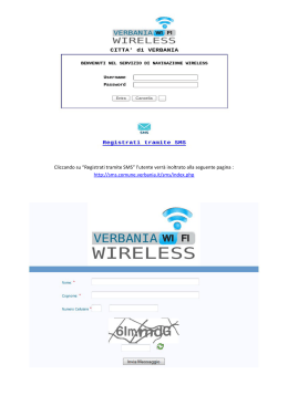
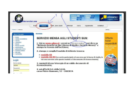
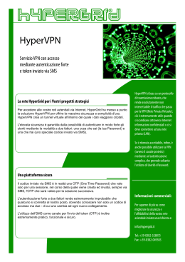
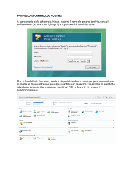
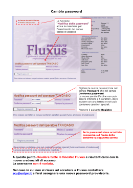
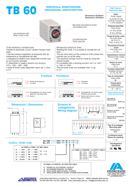
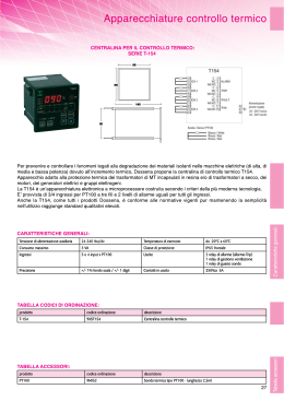
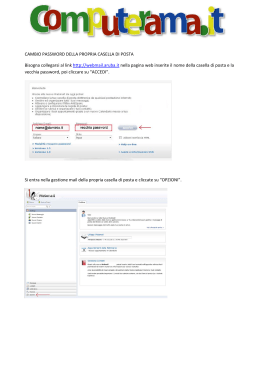
COMBINATORE TELEFONICO
TELEPHONE DIALLER
GMTEL 3
Tre i Systems S.r.l.
Sommario
Pagina
1.0 Funzioni principali.................................................................................................................................. 3
1.1 Indicazione dei led.................................................................................................................................. 3
1.2 indicazione delle parti ............................................................................................................................ 4
1.3 collegamento degli ingressi .................................................................................................................. 5
1.4 collegamento dello stato centrale ......................................................................................................... 5
1.5 inserimento della carta SIM e del fissaggio al muro ............................................................................ 5
1.6 Alimentazione ......................................................................................................................................... 6
2.0 Registrazione dei messaggi vocali ....................................................................................................... 6
2.1 Registrazione del primo messaggio vocale (Allarme Furto) ............................................................... 6
2.2 Ascolto del primo messaggio vocale .................................................................................................... 6
2.3 Registrazione del secondo messaggio vocale (Allarme Rapina) ........................................................ 6
2.4 Ascolto del secondo messaggio vocale ............................................................................................... 6
2.5 Registrazione del terzo messaggio vocale (Allarme Incendio) ........................................................... 6
2.6 Ascolto del terzo messaggio vocale ..................................................................................................... 7
2.7 Chiusura del Combinatore ..................................................................................................................... 7
3.0 Memorizzazione dei Numeri telefonici .................................................................................................. 7
3.1 Cambio della Password ......................................................................................................................... 7
3.2 Cancellazione di un numero telefonico in memoria............................................................................. 7
3.3 Personalizzazione dei messaggi SMS inviati dal combinatore ........................................................... 8
3.4 Invio dei messaggi voce senza SMS .................................................................................................... 8
3.5 Disabilitare blocco ciclo delle telefonate dei numeri preselezionati .................................................. 8
3.6 Abilitare blocco ciclo delle telefonate dei numeri preselezionati ....................................................... 9
4.0 Funzionamento in caso di Allarme ........................................................................................................ 9
4.1 Reset dell’Allarme da combinatore ....................................................................................................... 9
4.2 Reset dell’Allarme da remoto ................................................................................................................ 9
4.3 Ascolto ambientale e viva-voce............................................................................................................. 9
5.0 Controllo dei Relè per l’automazione della casa ................................................................................ 10
5.1 Stato dei Relè ........................................................................................................................................ 10
5.2 Attivazione e disattivazione da remoto del Relè 1 ............................................................................. 10
5.3 Attivazione e disattivazione da remoto del Relè 2 ............................................................................. 10
5.4 Attivazione e disattivazione da remoto del Relè 3 ............................................................................. 10
6.0 Allarme Tamper .................................................................................................................................... 11
7.0 Ripristino totale - impostazioni di fabbrica........................................................................................ 11
8.0 Caratteristiche Tecniche ...................................................................................................................... 11
Summary
page
1.0 Main functions ..................................................................................................................................... 13
1.1 Indication of the led .............................................................................................................................. 13
1.2 Part identification ................................................................................................................................. 14
1.3 Trigger input connections ................................................................................................................... 15
1.4 Control Panel Status ............................................................................................................................ 15
1.5 Insert SIM card and wall fixing ............................................................................................................ 15
1.6 Powering up the GMTEL-3 ................................................................................................................... 16
2.0 Recording the voice messages ........................................................................................................... 16
2.1 Recording the first voice message (Burglary alarm) ........................................................................ 16
2.2 Playback first message recorded ........................................................................................................ 16
2.3 Recording second voice message (Fire Alarm) ................................................................................. 16
2.4 Playback second message recorded .................................................................................................. 16
2.5 Recording third voice message (Hold up or Medical Distress Alarm) .............................................. 16
2.6 Playback third message recorded ....................................................................................................... 16
2.7 Closing the telephone dialler ............................................................................................................... 17
3.0 To memorize telephone numbers ........................................................................................................ 17
3.1 To change password ........................................................................................................................... 17
3.2 To cancel memorized telephone number .......................................................................................... 17
3.3 Personalize SMS messages ................................................................................................................ 18
3.4 How to send voice without SMS messages ........................................................................................ 18
3.5 Disablement block phone numbers pre-selected cycle ..................................................................... 18
3.6 Enabling cycle block of pre-selected telephone numbers ................................................................ 19
4.0 Alarm trigger procedure....................................................................................................................... 19
4.1 To reset false alarm trigger .................................................................................................................. 19
4.2 Remote alarm trigger reset .................................................................................................................. 19
4.3 Listen-in and two way communication ............................................................................................... 20
5.0 Remote control of onboard Relays ..................................................................................................... 20
5.1 Relay Status .......................................................................................................................................... 20
5.2 Remote control of Relay 1 ................................................................................................................... 20
2
5.3 Remote control of Relay 2.................................................................................................................... 20
5.4 Remote control of Relay 3.................................................................................................................... 20
6.0 Tamper Alarm is indication of power failure and battery state ......................................................... 21
7.0 Total GMTEL-3 Reset to factory setting .............................................................................................. 21
8.0 Technical Characteristics .................................................................................................................... 21
La Tre i Systems, ha sviluppato questo nuovo combinatore GSM di facile utilizzo. Le applicazioni di questo combinatore sono molteplici per la trasmissione di un allarme. Questo manuale è rivolto all’installazione del GMTEL-3
abbinato ad un impianto anti intrusione. Le principali segnalazioni sono: Furto, Incendio, Rapina o emergenza
medica. L’uso improprio del prodotto declina ogni responsabilità all’Azienda costruttrice e nello stesso tempo ne
decade la garanzia.
1.0 Funzioni Principali
•
•
•
•
•
•
•
•
•
•
•
•
Alimentazione compresa tra 12 e 24 V cc.
2 Led di stato modulo GSM: uno per l’attività del modulo e l’altro per il livello di campo.
3 messaggi vocali personalizzabili: 10 sec. per ciascun messaggio.
3 messaggi SMS personalizzabili: fino a 75 caratteri per ciascun messaggio.
5 numeri memorizzabili per l’invio di messaggi SMS e vocali.
Programmazione per l’invio di messaggi SMS e vocali per ciascun numero.
3 ingressi di allarme via filo attivabili (a negativo, a positivo e a apertura contatto).
1 ingresso per stato centrale attivabile (a negativo, a positivo e a apertura contatto).
3 uscite relè a scambio libero per l’automazione della casa.
Batteria interna, garantisce il normale funzionamento fino a 3 ore.
Invio messaggi di: mancanza alimentazione, batteria scarica e manomissione.
Ascolto ambientale bidirezionale.
1.1 Indicazione dei Led
Fig.1
Indicazione
Descrizione
12 / 24 V dc
Indicatore di presenza alimentazione.
Relay 1
Stato del relè n. 1: è acceso se il relè è attivato
Relay 2
Stato del relè n. 2: è acceso se il relè è attivato
Relay 3
Stato del relè n. 3: è acceso se il relè è attivato
GSM Power
Indica il livello di campo GSM.
Spento : non vi è presenza di campo;
Rosso : il campo risulta debole;
Verde: il campo è buono.
Record
Registrazione in corso del messaggio vocale
Alarm Trigger
Allarme in corso: invio dei messaggi in corso
GSM Net
Il suo lampeggio indica che il modulo è acceso e funzionante.
Diversamente se è spento indica la mancanza di campo o
modulo non funzionate.
3
1.2 Indicazione delle parti
Morsettiera uscite relè
Microfono per l’ascolto
ambientale
Pulsante PROGRAM
Modulo GPRS
Indicatori luminosi
Microfono per la registrazione dei messaggi
vocali
Dip Switch
Altoparlante
Morsettiera ingressi
allarmi e alimentazione
Fig.2
Connettore della batteria
Descrizione della morsettiera
Morsetto
Indicazione
16
15
Descrizione
N.C. Relè 3
3-COM
Comune Relè 3 (carico:12V 3A, 220V 3A)
14
N. A. Relè 3
13
N.C. Relè 2
12
2-COM
Comune Relè 2 (carico: 12V 3A, 220V 3A)
11
N. A. Relè 2
10
N.C. Relè 1
9
1-COM
8
Comune Relè 1 (carico: 12V 3A, 220V 3A)
N. A. Relè 1
7
UNIT
Stato Centrale / Reset ciclo chiamate
6
IN3
Ingresso 3
5
IN2
Ingresso 2
4
IN1
Ingresso 1
3
GND
2
- POWER
- Negativo
1
+ POWER
+ 12/24 V
Negativo
4
1.3 Collegamento ingressi allarme
Importante: la resistenza da 100K ohm montata sulla morsettiera serve per il corretto funzionamento; seguire le
seguenti indicazioni.
Gli ingressi per il collegamento del GMTEL3 con la Centrale sono: FURTO (Ingresso 1), INCENDIO (Ingresso
2) ,RAPINA o SOCCORSO MEDICO (Ingresso 3) e stato della centrale (Stato centrale / Reset).
Le seguenti indicazioni sono valide se l’installazione del GMTEL3 viene effettuata con una Centrale provvista di
uscita “Stato della Centrale”(controllare attentamente il manuale della Centrale). Diversamente, basta lasciare la
resistenza di 100K ohm ai morsetti 7 e 3; in questo modo tutti gli ingressi possono essere pronti, in ogni momento,
per avviare il ciclo delle chiamate.
L’ingresso 1 è subordinato allo stato della Centrale; se la Centrale è disinserita, esso non produce l’avvio delle
chiamate.
L’ingresso 2 e 3 sono indipendenti dallo stato della Centrale.
Seguire le seguenti indicazioni per il collegamento tra il GMTEL3 e la Centrale.
Impostare il Dipswitch
secondo le uscite della
Vostra centrale.
Segnale Ingressi morsettiera
centrale IN1 IN2 IN3 UNIT
Negativo
-
-
-
-
Positivo
+
+
+
+
DIP
1
2
3
4
1
Nota: ogni ingresso è
indipendente
2
3
4
DIPSWITCH
Esempi:
⇒ Se la Centrale, in fase di allarme Furto, emette un segnale negativo, occorrerà impostare il Dipswitch
1a
“-” e collegarlo al morsetto IN1(4); se la Centrale, in caso d’incendio, emette un segnale positivo, occorrerà
impostare il Dipswitch 2 a “+” e collegarlo sul morsetto IN2(5); se la Centrale, in caso di rapina o soccorso
medico, emette un segnale negativo, occorrerà impostare il Dipswitch 3 a “-” e collegarlo sul morsetto IN3
(6).
⇒ Se
la Centrale, sprovvista di uscite proprie, attiva un relè per ogni tipo di segnalazione; in questo caso
occorre collegare al comune un positivo o un negativo, all’uscita del scambio NO collegarlo al morsetto del
combinatore (esempio IN1) e impostare il Dipswitch corrispondente al morsetto del combinatore scelto.
1.4 Collegamento Stato Centrale
Attraverso questo ingresso è possibile far conoscere lo stato della centrale al GMTEL-3; di seguito riportiamo i
seguenti casi:
•
•
A presenza di negativo o positivo, sul morsetto UNIT (7) , il GMTEL3 riconosce che la Centrale è Inserita.
Sul morsetto UNIT (7) non è presente alcun segnale, il GMTEL3 riconosce che la Centrale è disinserita.
1.5 Inserimento della Carta Sim e del fissaggio al muro
Il fissaggio del GMTEL3 è reso facile dai
fori presenti. Prima del fissaggio occorre
inserire la carta SIM. Accertarsi poi che il
passaggio dei cavi non ostacoli il fissaggio al muro
5
l’inserimento della SIM avviene attraverso uno sportello presente nella parte
posteriore del combinatore. La prima cosa da fare, prima di fissare il combinatore su parete e prima di fornire alimentazione, è inserire la SIM.
Rimuovere il coperchio indicato in figura.
Inserire La Sim.
Chiudere il coperchio.
Nota: La carta SIM deve essere priva del codice PIN.
Utilizzare un telefono cellulare per sbloccare il codice.
1.6 Alimentazione - Accendere il GMTEL3
Il GMTEL3 può essere alimentato direttamente dalla Centrale o da un alimentatore esterno; occorre precisare che
la segnalazione “No ext Power” (Mancanza alimentazione esterna), mediante messaggio SMS, è riferita solamente alla mancanza di alimentazione presenti sui morsetti.
Il funzionamento è garantito anche per tensioni superiori ai 12 Vcc, fino ad un massimo di 24 Vcc; non superare
tale valore (decade la garanzia di funzionamento).
1]
2]
3]
4]
Una volta cablata l’alimentazione, il GMTEL3, in fase di avvio, accende tutti i led;
collegare la batteria e aspettare che il GMTEL3 esegua tutte le operazioni.
Dopo circa un minuto, i led 12 V, GSM Power e Gsm Net rimangono accesi: il combinatore è pronto.
Si prosegue l’installazione con la registrazione dei messaggi vocali.
2.0 Registrazione dei messaggi vocali
Il combinatore telefonico, così come per gli SMS, invia 3 differenti messaggi vocali ai 5 numeri presenti in memoria
a seconda del tipo di allarme attivato.
2.1 Registrazione del primo messaggio vocale (Allarme Furto)
Per registrare il primo messaggio è sufficiente premere il pulsante “PROGRAM”1, il led “RELAY 1”2 si accende a
conferma. Se entro 6 secondi viene nuovamente premuto il tasto “PROGRAM” si accenderà anche il led
“RECORD”2 che conferma l’attivazione della registrazione. A questo punto è possibile registrare il primo messaggio
vocale di 10 secondi. E’ importante evitare rumori di fondo durante la registrazione del messaggio.
2.2 Ascolto del primo messaggio vocale
Per ascoltare il primo messaggio è sufficiente premere il pulsante “PROGRAM”1, il led “RELAY 1”2 si accende a
conferma. Dopo 6 secondi inizierà la riproduzione del primo messaggio vocale
2.3 Registrazione del secondo messaggio vocale (Allarme Rapina)
Dopo aver registrato e ascoltato il primo messaggio si accenderà il led “RELAY 2”, premendo entro 6 secondi,
dall’accensione di “RELAY 2”2, il tasto “PROGRAM”1 sarà possibile registrare il secondo messaggio vocale di 10
secondi. A conferma dell’attivazione della registrazione si accenderà il led “RECORD”2.
2.4 Ascolto del secondo messaggio vocale
Dopo aver registrato e ascoltato il primo messaggio si accenderà il led “RELAY 2” 2, dopo 6 secondi si ascolterà il
contenuto del secondo messaggio vocale memorizzato.
2.5 Registrazione del terzo messaggio vocale (Allarme Incendio)
Dopo aver registrato e ascoltato il secondo messaggio si accenderà il led “RELAY 3”, premendo entro 6 secondi,
dall’accensione di “RELAY 3”, il tasto “PROGRAM”1 sarà possibile registrare il terzo messaggio vocale di 10 secondi. A conferma dell’attivazione della registrazione si accenderà il led “RECORD”2.
2.6 Ascolto del terzo messaggio vocale
Dopo aver registrato e ascoltato il secondo messaggio si accenderà il led “RELAY 3”2, dopo 6 secondi, si ascolterà
il contenuto del terzo messaggio vocale memorizzato.
1
2
Vedi Fig. 2 (Pag. 4)
Vedi Fig. 1 (Pag. 3)
6
2.7 Chiusura del Combinatore
Una volta chiuso il coperchio del combinatore si attiverà la funzione “Allarme Tamper” (vedi par. 6.0).
3.0 Memorizzazione dei Numeri telefonici
La memorizzazione dei numeri telefonici all’interno del combinatore avviene attraverso messaggi SMS. Ciò
significa che è necessario conoscere il numero telefonico della scheda SIM inserita nel combinatore stesso.
Per inserire un numero telefonico si deve comporre un messaggio SMS rispettando questa sintassi:
Password +DD+Posizione+Numero telefonico
La posizione è un numero compreso tra 1 e 5 e rappresenta la posizione del numero telefonico all’interno dei 5 slot
disponibili in memoria. Quando il combinatore va in allarme chiamerà i numeri memorizzati nella sequenza da 1 a
5.
Esempio: per programmare il numero telefonico 32012345678, come primo numero (posizione 1) sapendo che la
password e 1234 è necessario inviare un SMS così composto:
1234DD132012345678
Il combinatore, ricevuto il messaggio, invierà conferma, esclusivamente al numero master che è quello programmato in posizione 1, ed inserirà nel testo del messaggio anche i numeri telefonici delle altre posizioni anche se non
sono ancora state registrate. Inoltre darà informazioni sulla password attualmente impostata.
Il messaggio di risposta è così composto:
GMTEL3
TELEPHONE NUMBER
1. numero memorizzato in posizione 1
2.
3.
4.
5.
PASSWORD:
1234 (di default)
3.1 Cambio della Password
La password impostata in fabbrica è 1234.
Per cambiare la password, con un altra composta sempre da 4 cifre, è necessario spedire un SMS, al numero della
scheda SIM inserita nel combinatore, così composto:
Vecchia Password+DD7+Nuova Password
Esempio: partendo dalla password iniziale (1234) si vuole impostare la nuova password che deve essere 9876.
Per fare ciò è necessario spedire questo messaggio SMS:
1234DD79876
3.2 Cancellazione di un numero telefonico in memoria
Come per la memorizzazione di un numero, la cancellazione avviene inviando un messaggio SMS alla scheda
inserita nel combinatore telefonico. La cancellazione avviene rispettando la seguente sintassi:
Password+DD+Posizione
Esempio: per cancellare il numero memorizzato in posizione n. 2, quando la password è 1234 si dovrà comporre
questo SMS:
7
3.3 Personalizzazione dei messaggi SMS inviati dal combinatore
Questo combinatore può inviare 3 differenti messaggi SMS, selezionati a seconda del tipo di allarme, ai numeri
inseriti nella sua memoria.
Il messaggio 1 viene inviato in caso di allarme furto, il messaggio 2 viene inviato in caso di allarme incendio, il
messaggio 3 viene inviato in caso di allarme rapina.
Per personalizzare questi messaggi è necessario spedire un SMS alla scheda SIM inserita nel combinatore così
composto:
Password + DM0 + Numero Messaggio + Testo del Messaggio
Esempio: si vuole personalizzare l’SMS spedito in caso di incendio (messaggio 2), quando la password è 1234,
con il testo “Allarme incendio”. Per fare ciò si comporrà il seguente SMS:
1234DM02Allarme incendio
Il combinatore, ricevuto il messaggio, risponderà al numero master (posizione 1) con un SMS con su scritto il testo
del messaggio impostato.
Nota: L’SMS può contenere un massimo di 75 caratteri.
3.4 Invio messaggi voce senza sms.
Se si vuole inviare solo il messaggio vocale, senza il messaggio SMS, bisogna inviare il seguente messaggio:
Password + DM0 + Numero Messaggio +#
Esempio: si vuole inviare solo il messaggio vocale (messaggio 1) , quando la password è 1234. Per fare ciò si
comporrà il seguente SMS:
1234DM01#
Il combinatore, ricevuto il messaggio, risponderà con un SMS con su scritto il l’avvenuto comando
Nota: il Combinatore cancella il messaggio di testo impostato . Per ripristinarlo vedere il par. 3.3
3.5 Disabilitare blocco ciclo delle telefonate dei numeri preselezionati
I cinque numeri telefonici memorizzati sono abilitati, come impostazione di fabbrica, a bloccare il ciclo delle chiamate; ogni volta che si riceve la telefonata, l’utente può bloccare il GMTEL3 con il tasto #, al termine del messaggio
vocale.
Se non si desidera che alcuni numeri preselezionati possano bloccare il ciclo, occorre eseguire il seguente messaggio:
Password +PN+posizione numero telefonico.
Esempio: si vuole disabilitare il 2° e il 4° numero a bloccare il ciclo delle chiamate; inviare al combinatore il seguente messaggio:
1234PN24
Il GMTEL-3 invia il seguente messaggio di risposta:
GMTEL-3:
1Y
2N
3Y
4N
5Y
Dove per N indica il numero disabilitato al blocco del ciclo delle chiamate.
8
3.5 Abilitare blocco ciclo delle telefonate dei numeri preselezionati
Descritto nel paragrafo precedente, possiamo scegliere quali numeri sono abilitati a bloccare il ciclo delle chiamate.
Se si desidera riabilitare un numero preselezionato al blocco del ciclo delle chiamate occorre eseguire il seguente
messaggio:
Password +PY+posizione numero telefonico.
Esempio: si vuole abilitare il 4° e il 5° numero a bloccare il ciclo delle chiamate; inviare al combinatore il seguente
messaggio:
1234PY45
Il GMTEL3 invia il seguente messaggio di risposta:
GMTEL-3:
1Y
2N
3Y
4Y
5Y
Dove per Y indica che quel numero è abilitato al blocco del ciclo delle telefonate
4.0 Funzionamento in caso di Allarme
Quando la centrale và in allarme, in GMTEL3 avvio il ciclo delle chiamate. Il primo messaggio inviato è un SMS (se
abilitato) al primo numero preselezionato; subito dopo, il primo numero riceve una chiamata telefonica dal combinatore con il messaggio vocale preregistrato; al termine del messaggio, se l’utente è abilitato, premendo il tasto “#”
il combinatore blocca il ciclo delle chiamate, altrimenti può semplicemente riagganciare. Di seguito il combinatore
passerà al secondo numero, fino all’ultimo numero, seguendo la stessa sequenza: prima l’invio del messaggio
SMS e poi la chiamata telefonica. Alla fine del terzo ciclo delle chiamate, se nessuno risponde o blocca la sequenza, il GMTEL3 torna in standby.
4.1 Reset in caso di falso allarme da combinatore
In caso di falso allarme, si può bloccare automaticamente il combinatore semplicemente disinserendo la Centrale.
( vedere il paragrafo 1.4)
4.2 Reset dell’Allarme da remoto
Per disinserire la Centrale in allarme da remoto, occorre effettuare un collegamento tra la Centrale e il GMTEL3;
collegare uno dei relè del GMTEL3 con la chiave meccanica della Centrale (ove prevista) o ad un ingresso preposto; mandare un messaggio di attivazione o disattivazione tramite questo relè. Vedere il paragrafo 5.0 e consultare
il manuale della Centrale.
4.3 Ascolto ambientale e viva-voce
Quando si riceve la chiamata vocale dal combinatore, alla fine dell’ascolto del messaggio, si può premere sul
proprio telefono il tasto “*” (asterisco). Il combinatore non terminerà la chiamata ma attiverà il microfono interno. In
questa modalità è possibile ascoltare ciò che avviene nell’ambiente protetto ed in caso di “SOCCORSO MEDICO”
si potrà parlare con la persona presenta nell’ambiente circostante al GMTEL 3.
Nota: la Società declina ogni responsabilità sull’uso improprio di questa funzione.
9
5.0 Controllo dei Relè per l’automazione della casa
Questo combinatore dispone di 3 differenti Relè che possono essere attivati o disattivati da remoto inviando un
SMS al numero della scheda inserita nel combinatore. E’ inoltre possibile conoscere lo stato dei 3 relè.
Nota: si intende relè attivo quando viene chiuso lo scambio relè comune N. A.
5.1 Stato dei Relè
Per conoscere lo stato dei relè è sufficiente spedire al combinatore un messaggio SMS così composto:
Password + RS
Il combinatore, in risposta, invierà un SMS con lo stato attuale dei 3 relè.
Esempio: per conoscere lo stato dei relè quando la password è 1234 si dovrà inviare il seguente SMS: 1234RS
In risposta il combinatore invierà un messaggio così composto:
GMTEL3
RELAY 1 STATUS: OFF
RELAY 2 STATUS: ON
RELAY 3 STATUS: OFF
5.2 Attivazione e disattivazione da remoto del Relè 1
Per attivare il relè 1 è necessario spedire un SMS così composto:
Password+A1
Per disattivarlo il messaggio sarà:
Password+A2
5.3 Attivazione e disattivazione da remoto del Relè 2
Per attivare il relè 1 è necessario spedire un SMS così composto:
Password+B1
Per disattivarlo il messaggio sarà:
Password+B2
5.4 Attivazione e disattivazione da remoto del Relè 3
Per attivare il relè 1 è necessario spedire un SMS così composto:
Password+C1
Per disattivarlo il messaggio sarà:
Password+C2
Esempio 1: Si vuole attivare il Relè n. 2 quando la password impostata è 1234; il messaggio da comporre sarà:
1234B1
Esempio 2: Si vuole disattivare il Relè n. 1 quando la password impostata è 1234; il messaggio da comporre sarà:
1234A2
10
Nota: Lo stato di ogni relè viene trasmesso con un messaggio SMS in Inglese; ecco ciò che viene segnalato dal
combinatore:
Relè
SMS
Significato
Relè 1
Relay 1 activated
Relè 1 attivato
Relè 1
Relay 1 deactivated
Relè 1 disattivato
Relè 2
Relay 2 activated
Relè 2 attivato
Relè 2
Relay 2 deactivated
Relè 2 disattivato
Relè 3
Relay 3 activated
Relè 3 attivato
Relè 3
Relay 3 deactivated
Relè 3 disattivato
6.0 Indicazione - Allarme Tamper - Mancanza Alimentazione
Questo combinatore è provvisto di un pulsante antimanomissione (Tamper) interno ; nel momento in cui la scatola
viene aperta o manomessa, il GMTEL3 manda il seguente messaggio SMS:
- Case opened = Coperchio aperto
Il GMTEL3 è dotato di segnalazione di mancanza alimentazione esterna ; i messaggi sono:
Messaggio
Descrizione
No Power external
Mancanza alimentazione
External power OK
Ritorno alimentazione
7.0 Ripristino totale - impostazioni di fabbrica
Per ripristinare il combinatore con le impostazioni di fabbrica occorre:
⇒ Scollegare la batteria e l’alimentazione sterna
⇒ Tenere premuto il tasto “PROGRAM” e ridare l’alimentazione: rilasciare il tasto dopo 30 secondi o quando
si sente “scattare” uno dei relè presenti sulla scheda.
⇒ Ricollegare la batteria
⇒ A questo punto saranno cancellati tutti messaggi vocali, di testo e i numeri telefonici memorizzati. La
password ritorna ad essere: 1234
8.0 Caratteristiche Tecniche
•
•
•
•
•
•
•
•
•
•
•
Alimentazione: 12-24 V cc
Batteria interna: 7.2 V
Assorbimento a riposo: 35 mA
Assorbimento massimo: 90 mA
Tempo minimo attivazione : 500 msec
Contatti relè, carico massimo: 3 A (220Vac) - 3 A (30Vcc)
Modulo GSM: SICOM300Z GSM-GPRS TRIBAND (900/1800/1900 MHz)
Tecnologia SMD
Carte SIM supportate e verificate: Vodafone, Tim e Wind
Dimensioni: 181x107x36 mm (contenitore in ABS)
Peso: 300 gr.
La Tre I Systems non è responsabile dell’uso improprio dei suoi prodotti.
Per qualsiasi problema rivolgersi al più vicino rivenditore autorizzato o centro assistenza e I
Systems.
11
TAVOLA RIEPILOGATIVA DEI COMANDI
TRAMITE MESSAGGI SMS
Funzione
Comando
Esempio
Password+DD+posizione+numero telefonico
1234DD132012345678
Vecchia password+DD7+nuova password
1234DD79876
Password+DD+posizione numero
1234DD2
Password+ DM0+numero messaggio+testo messaggio
1234DM01ALLARME FURTO
Password+DM0+numero messaggio+#
1234DM01#
Password+RS
1234RS
Password+PN+posizione dei numeri telefonici da
disabilitare
1234PN24
Password+PY+Posizione dei numeri telefoni da abilitare
1234PY135
Attivare il relè 1 “ON”
Password+A1
1234A1
Disattivare il relè 1 “OFF”
Password+A2
1234A2
Attivare il relè 2 “ON”
Password+B1
1234B1
Disattivare il relè 2 “OFF”
Password+B2
1234B2
Attivare il relè 3 “ON”
Password+C1
1234C1
Disattivare il relè 3 “OFF”
Password+C2
1234C2
Memorizzazione dei numeri telefonici
Cambio della password
Cancellazione di un numero telefonico in
memoria
Personalizzare un messaggio SMS
Inviare solo messaggi voce
Stato relè
Disabilitare i numeri telefonici a bloccare il
ciclo delle chiamate.
Abilitare i numeri telefonici a bloccare il
ciclo delle chiamate.
Contiene batteria ricaricabile a polimeri di Litio. Non disperdere nell’ambiente.
Non disperdere nell’ambiente. Portare l’apparecchio negli appositi centri di
smaltimento
12
With years of experience the manufacturing of products using GSM technology, Treisystems s.r.l. has developed
this new user friendly automatic telephone dialler.
The application of this product is to automatically, through the GSM net work, send vital information and data in
case of an emergency. Typical application of this dialler is in the case of Burglary, Fire; Hold-up, or Medical Distress alarms.
1.0 Main Function
•
•
•
•
•
•
•
•
•
•
•
•
Power from 10 to 24 Volt D.C.
2 GSM Led indications: One for GSM power level. Other for GSM modem functions.
Possibility to memorize 3 personalized messages of 10 seconds each.
Possibility to memorize 3 personalized SMS messages of 75 characters each.
Possibility to memorize up to 5 different tel. Numbers to send SMS & Voice messages.
Possibility to program dialler to send only SMS or only Voice messages.
3 Alarm trigger inputs activated by (negative, positive or open contact)
1 input to arm/disarm control panel by (negative, positive or open contact)
3 Free dry contact relay outputs for home automation.
Rechargeable battery back-up incorporated. (guarantees normal function for 3 hours.)
Will send automatic SMS message in case of: Low battery-Power failure-Tampering.
Listen-in and two way communication functions incorporated.
1
1.1 Indication of the Leds
Fig.1
LED
FUNCTIONS
12 to 24Vdc.
Indication of power present “LED ON” when powered up
Relay 1
Status of relay n. 1: Led is “ON” if relay is activated
Relay 2
Status of relay n. 2: Led is “ON” if relay is activated
Relay 3
Status of relay n. 3: Led is “ON” if relay is activated
GSM Power Level
Indicates GSM signal level
OFF :
No GSM signal present
RED :
Weak GSM signal present
GREEN: Strong GSM signal present
Record
Led is “ON” during message recording
Alarm Trigger
Led is “ON” during dialler trigger cycle
GSM Net
Led flashing is an indication that the GSM module is functioning correctly. If
“OFF” means that the GSM module is not functioning or that the GSM
power signal is not present.
13
1.2 Part indication
Relays terminals block
Surrounding
microphone
PROGRAM button
GPRS Module
Leds
Voice record
microphone
Dipswitch
Speaker
Input terminal block
and supply
Battery Connector
Fig.2
2
Terminal Block
Terminal
Indication on
PCB
16
15
Description
N.C. Relay 3
3-COM
Common Relay 3 (max load:12V 3A, 220V 3A)
14
N. A. Relay 3
13
N.C. Relay 2
12
2-COM
Common Relay 2 (max load: 12V 3A, 220V 3A)
11
N. A. Relay 2
10
N.C. Relay 1
9
1-COM
8
Common Relay 1 (max load: 12V 3A, 220V 3A)
N. A. Relay 1
7
UNIT
Panel status / Reset of trigger cycle.
6
IN3
Terminal input 3
5
IN2
Terminal input 2
4
IN1
Terminal input 1
3
GND
2
- POWER
- Negative
1
+ POWER
+ Positive 12/24 V
3
Negative
14
1.3 Trigger input connections
4
Important: The 100K ohm resistance assembled on the terminal blocks is necessary for correct functioning of this
telephone dialler without Unit Status Control. Follow the instructions below:
The trigger connections between the control panel and the GMTEL-3 are: BURGLARY (IN1), FIRE ( IN2) and
HOLD-UP or MEDICAL DESTRESS (IN3) and Panel Status o Reset (UNIT).
The following indication is valid if the control panel installed with the GMTEL-3 has an output for the control of the
“Panel’s Status”. (To determine this read carefully the installation manual of the control panel). If your control
panel does not have the “Panel Status” function, you may connect from terminal 7 and 3 the 100k ohm resistor and
set the dipswitch no. 4 in “-”. This will make all trigger inputs ready to start an alarm trigger cycle.
The IN1 input depends on the state of the Control Panel; if it is Disarmed, the Gmtel-3 can not start an alarm trigger
cycle. A trigger cycle may be started on if the panel is in Armed.
Trigger inputs 2 & 3 will function independent of the control panel’s status.
5
Follow the below instruction for the connections between GMTEL-3 and Control Panel.
Set Dipswitch compatibly
with terminal block output
of your Control panel
Note: every terminal
block are independently
Examples:
⇒
Control
Panel Signals
Terminal Block
IN1 IN2 IN3
UNIT
Negative
-
-
-
-
Positive
+
+
+
+
DIP
1
2
3
4
1
2
3
4
DIPSWITCH
If the Control Panel is in Burglary alarm mode, and produces a negative, it must be connected to the
terminal No. 4 (IN1) and set the dipswitch no. 1 in “-”; if in Fire alarm mode and produces a positive, it
must be connected to terminal No. 5 (IN2) and set the dipswitch no.2 in “+”; if in Hold-up or Medical Distress, and produces a negative signal, it must be connected to Terminal No. 6 (IN3 ) and set the dipswitch no. 3 in “-”.
⇒
If the Control Panel does not have dedicated trigger outputs but only relay output for every type of alarm; it
will be necessary to insert the 100 k ohm resistor; after, you must connect a positive or a negative to
Common contact and connect from NO contact to terminal block no. 4 and set the dipswitch no.1 in “+” or
“-”
1.4 Control Panel Status Connections
Through this input it is possible to have the status of the control panel known to GMTEL-3 as shown below:
•
•
With a negative o a positive on terminal No.7 (UNIT), the GMTEL-3 will consider the Control Panel to be
in Armed status.
On terminal 7 (UNIT) there is no voltage present, the GMTEL-3 will consider the Control Panel to be in
Disarmed status.
1.5 Inserting the SIM card and WALL fixing
Fixing the GMTEL-3 to a surface is made easy
by the present STOP holes on the housing.
Insert the SIM card before fixing to wall. Also
make sure that there is enough room for cable
installation.
15
The SIM card is inserted through a small door seen on the backside of the
Gmtel-3. Before fixing the unit to the wall and before supplying power, it is
necessary that the SIM CARD be correctly inserted.
Note: The SIM must be without any PIN code.
If a PIN code is installed, it may be removed with any normal cellular telephone.
1.6 POWERING UP THE GMTEL-3
The GMTEL-3 may receive its power directly from a Control Panel or from a separate power supply. The SMS fty.
set message “No ext Power” . This message is sent only when power on the terminal block fails.
The Gmtel-3 will function correctly with voltage from 12 to 24Vdc. .
1]
2]
3]
4]
Once the GMTEL3 has received power all the Leds on the front panel will light as indication of start-up.
Connect the backup battery and wait until GMTEL- 3 goes through it internal start up stage.
After about one minute, the led 12 Vdc, GSM Power and GSM Net remain “ON”: the dialler is now ready.
Proceed the installation with the recording of the voice messages.
2.0 Recording of voice messages
The telephone dialler may send 3 different SMS and Voice messages to 5 different programmed telephone
Numbers based on the alarm trigger received.
2.1 Recording the first voice message (Burglary Alarm)
To record the first voice message press “PROGRAM”1 button on the PCB, the led “RELAY 1”2 will light to confirm. If
with-in 6 seconds the “PROGRAM” button is pressed again, the led “RECORD” will light to
confirm that a 10 second recording time has starter. During this time period you must speak clearly into the microphone located in the centre of the PCB. It is important to avoid back ground noise that may disturb the recording.
2.2 Playback of first message recorded
To listen to the first message recorded, press the “PROGRAM”1 button the led “RELAY 1”2 will light as
confirmation and after 6 seconds you will hear the playback of the first voice message.
2.3 Recording the second voice message (Fire Alarm)
After having recorded and listen to the playback of the first message, the led “RELAY 2”2 will light. By pressing,
with-in 6 seconds, the button “PROGRAM”1, the led “RECORD” will light and you may record your second 10 second voice message.
2.4 Playback of the second message recorded
After having record or listened to the first message the “RELAY 2”2 will light and after 6 seconds you will hear the
playback of the second voice message.
2.5 Recording the third voice message (Hold-up or Medical Alarm)
After having recorded and listened to the second message the led “RELAY 3”2 will light, by pressing with-in 6 seconds, the “PROGRAM”1 button the led “RECORD” will light and you may go ahead with the recording of
the 3rd voice message.
2.6 Playback of third message recorded
After having recorded or listened to the playback of the 2nd voice message the led “RELAY 3”2 will light and after 6
seconds you will hear the playback of the 3rd message recorded.
1
2
See Fig. 2 (Page 14)
See Fig. 1 (Page 13)
16
2.7 Closing the GMTEL-3 housing
Once the front cover is replaced on the housing, the “Tamper Alarm” will go into function. (see parg. 5.0).
3.0 To memorize telephone numbers
Memorizing telephone numbers in the GMTEL-3 is done by sending SMS messages from your normal cellular
telephone. To do this, you must know the telephone number of the SIM card place in the
GMTEL-3 dialler.
To program a telephone number the following SMS message must be sent:
Password + DD + Position + telephone number
You may memorize up to 5 telephone numbers in the GMTEL-3. So the “POSITION” is a number between 1 to 5
that represents the memory slots in the dialler. When the dialler is trigger it will call the 5 numbers memorized
starting from slot 1 to slot 5
.
Example: To program the number 32012345678, in slot 1 or (position 1) knowing that the password is 1234 the
following SMS message must be sent.
1234DD132012345678
When the GMTEL-3 receives the numbers sent by SMS it will send confirmation to the first number memorized and
this number will be considered the master number and is programmed in slot 1. this message will contain also the
numbers in the other slots even if not yet memorized. Also the PASSWORD will be
included as shown below:
The reply message will be like this:
GMTEL3
TELEPHONE NUMBER
1. number memorized in slot 1
2.
3.
4.
5.
PASSWORD:
1234 (default)
3.1 To change Password
The factory programmed password is 1234. To change this password, with another of 4 figures, you must send an
SMS message to the GMTEL-3 as shown below:
Old Password + DD7 + New Password
Example: Starting with the old password (1234) you wish to insert a new Password (9876). To do this the following
SMS message must be sent:
1234DD79876
3.2 To cancel memorized telephone numbers
Cancelling numbers memorized is done in the same way as to memorize them:
Password+ DD+ Position
Example: To cancel the number memorized in slot or position 2, knowing that the password is 1234,
You must send to the GMTEL-3 the following SMS message:
1234DD2
17
3.3 Personalized SMS messages
This dialler can memorize and send 3 different SMS messages, the message maybe personalized base on the
trigger alarm sent by the GMTEL-3. Normally SMS message 1 is sent for Burglary alarm trigger message 2 for
Fire alarm trigger and message 3 for Hold-up of Medical Distress.
To personalize these messages it is necessary to send to the GMTEL-3 an SMS as shown below:
Password+DM0+Message Number + Message Text
Example: If you wish to personalize the SMS to be sent in case of Fire alarm trigger (message 2), when the password is (1234), with the text “Fire Alarm Trigger”. You must send the following SMS message to the dialler:
1234DM02Fire Alarm Trigger
After the GMTEL-3 receives this SMS, it will repeat the same message to the master number in slot 1 (position 1).
Note: Personalized SMS messages may contain up to 75 characters.
3.4 How to program voice messages without SMS
If you wish that the GMTEL-3 send only voice messages without SMS messages, you must send to the GMTEL-3
the following SMS command.
Password + DM0 + Number Message +#
Example: If you wish to send only voice message (message no. 1), when the password is (1234). The
following SMS message must be sent to the GMTEL-3 dialler:
1234DM01#
Once this message has been received, the dialler will reply with an SMS message showing the command.
Note: If there are SMS messages in the dialler memory, with the above command, they will be cancelled. To replace any message cancelled, follow the procedure on the above par. 3.3
3.6 Disablement cycle block of preselected telephone numbers.
6
The GMTEL3 can store up to 5 numbers, divided into five positions. The dialler is factory supplied so that all numbers called can block the alarm trigger by pressing “#”
To disable one or more numbers, run the following message:
Password +PN+position number
Example: You want to disable the 2nd and 4th number to stop the cycle of calls, the dialler to send the following
message:
1234PN24
The GMTEL-3 sends the following response message:
GMTEL-3:
1Y
2N
3Y
4N
5Y
Where P indicates that the number is unauthorized when the loop block calls
18
3.5 Enabling block phone numbers pre– selected cycle
7
Describe in the preceding paragraph, the GMTEL3 can enable/ disable preset phone numbers to block cycle call.
To enable one or more numbers, run the following message:
Password +PY +position number.
Example: You want to enable the 1st , 4th and 5th number to stop the cycle of calls, the dialler to send the following
message:
1234PY145
The GMTEL3 sends the following response message:
GMTEL-3:
1Y
2N
3Y
4Y
5Y
Where to Y indicates that the number is authorized to block the cycle of phone calls
4.0 Alarm trigger procedure
When the control panel is triggered, the gmtel-3 receives this trigger command and begins its alarm cycle.
The first message sent unless programmed differently is an Sms followed by a call to the telephone number
memorized with a 10 second pre-recorded voice message. At the end of this voice message if the number called is
enabled to cancel the alarm trigger, all that must be done is press the # symbol on the receiving telephone. If this
is not done, the gmtel-3 will continue to call all numbers memorized and send first the memorized Sms message
followed by the voice message until an enable receiver press the “#” symbol. by pressing the “#” symbol the gmtel3 will automatically reset itself for the next alarm trigger. If none of the memorized numbers reset the dialler with
the “#” symbol, the dialler will go through 3 cycles of calls after which it will reset itself automatically for the next
alarm trigger.
4.1 To Reset a false alarm trigger
In case of error and there is a false alarm trigger, the dialler maybe reset by disarming the control panel.
4.2 Remote Alarm reset
When a memorized telephone number receives a call from the dialler, after having listened to the voice
message, you may press the “#” button and the GMTEL-3 will stop sending both SMS and voice messages to the
other numbers memorized. Basically the dialler has been reset from a remote telephone. This function is factory
set for the master number (1). This same function, however, maybe set by the end user for the other numbers
memorized by following the instruction in par. xxxxx
4.3 Listen-in and 2 way communication
When the dialler calls a memorized tel. number, after having listened to the alarm trigger message, the receiving
number may press the “*” (asterisk). When this takes place the dialler will activate the onboard microphone and it
will be possible to listen to what is taking place in the protected area. In the case of a Medical Distress Alarm Trigger it is also possible to have 2 way communication with the patient seeking help.
19
5.0 Remote control of onboard Relays
The GMTEL-3 has onboard 3 Relays of which state of function maybe changed from a remote telephone by sending an SMS message to the dialler. It is also possible to know the state of function of each relay.
Note: An active relay is understood to be one in which the normally open become closed with the common.
5.1 Relay status
To know the status of a relay (active or dilative you must do is send an SMS message as shown below:
Password + RS
The GMTEL-3 will reply with an SMS showing the status of all 3 Relay to the master tel. No. Memorized.
Example: To know the status of the relays when the password is (1234) the below SMS must be sent:
1234RS
The GMTEL-3 will reply with an SMS similar to the one shown below:
GMTEL3
RELAY 1 STATUS: OFF
RELAY 2 STATUS: ON
RELAY 3 STATUS: OFF
5.2 Remote control of Relay 1
To activate “on” Relay 1 you must send this SMS message:
Password+A1
To deactivate “off” the message must be:
Password+A2
5.3 Remote control of Relay 2:
To activate “on” Relay 2 you must send this SMS message:
Password+B1
To deactivate “off” the message must be:
Password+B2
5.4 Remote control of Relay 3
To activate “on” Relay 3 you must send this SMS message:
Password+C1
To deactivate “off” the message must be :
Password+C2
Example: To activate Relay no. 2 when the password is (1234) the SMS to be sent is: 1234B1
To deactivate Relay no. 1 when the password is (1234) the SMS to be sent is: 1234A2
20
Note: The state of each Relay is sent with an SMS message in English; Below see the Italian translation:
Relay
SMS SENT
Italian translation
Relay 1
Relay 1 activated
Relè 1 attivato
Relay 1
Relay 1 deactivated
Relè 1 disattivato
Relay 2
Relay 2 activated
Relè 2 attivato
Relay 2
Relay 2 deactivated
Relè 2 disattivato
Relay 3
Relay 3 activated
Relè 3 attivato
Relay 3
Relay 3 deactivated
Relè 3 disattivato
6.0 Indications for: Tamper Alarm - Power Failure
The GMTEL-3 has an onboard (Tamper button). When the housing is open, a tamper alarm trigger will take place
and the dialler will send the following SMS message to the Master number memorized in position no.1:
Case opened
The GMTEL-3 will automatically also send SMS messages for power failure on connection terminals. When power
is cut the SMS message will be as shown below:
No Power external
If power is return to the terminals the below SMS message will be sent.
External Power OK
7.0 Total GMTEL-3 reset to factory setting
To totally reset the dialler to its original factory settings you must :
⇒ Totally disconnect all form of power (back-up battery and external power to the terminal blocks)
⇒
⇒
⇒
Maintain pressed the “PROGRAM” button and power up the unit: release the button after 30 seconds or
when you hear one of the relays on the PCB. change state .
Plug-in the backup battery.
At this point all Voice, SMS messages, telephone numbers memorized will be cancelled and the Password if changed will return to it original factory setting: 1234
8.0 Technical characteristics
•
•
•
•
•
•
•
•
•
•
•
Power: 12-24 V dc.
Built-in battery back-up: 7.2 V
Standby current drain: 35 mA
Maximum current drain: 90 mA
Minimum activation time: 500 msec
Maximum relay contact load: 3 A (220Vac.) - 3 A (30Vdc.)
GSM module: SICOM300Z GSM (900/1800) 1900Mhz. 3 Band
Technology SMD.
Supports SIM cards of your local GSM provider.
Dimension: 181x107x36 mm. (housing in ABS).
Weight: 300 gr.
TreISystems is not responsible for improper use of its products.
For any problem contact your local distributor or TreISystems repair centre.
21
SUMMARY TABLE OF
SMS COMMAND MESSAGES
Function
Command
Example
(password 1234)
To memorize telephone
numbers
Password+DD+Position+telephone
number
1234DD132012345678
To change the Password
Old Password+DD+new Password
1234DD79876
To cancel a memorized telephone number
Password+DD+Number Position
1234DD2
To personalize an SMS message
Password+DM0+message number+
Message text
1234DM01Burglary Alarm
Password+DM0+Message number+#
1234DM01#
Enabling block phone numbers preselected cycle.
Password+PY+position
1234PY135
Disablement cycle block of
preselected telephone numbers
Password+PN+position
1234PN24
Remote control of all Relays
Password+RS
1234RS
Activate Relay 1 to “ON”
Password+A1
1234A1
Deactivate Relay 1 to “OFF”
Password+A2
1234A2
Activate Relay 2 to “ON”
Password+B1
1234B1
Deactivate Relay 2 to “OFF”
Password+B2
1234B2
Activate Relay 3 to “ON”
Password+C1
1234C1
Deactivate Relay 3 to “OFF”
Password+C2
1234C2
To send only voice messages
8
9
Rechargeable Li-Ion battery.
Correct disposal of this product.
22
NUMERI TELEFONICI E MESSAGGI SMS MEMORIZZATI
TELEPHONE NUMBERS AND SMS MESSAGES MEMORIZED
Posizione
Position
Numero telefonico memorizzato
Telephone number memorized
1
2
3
4
5
Posizione
Position
Messaggi SMS memorizzati
SMS message memorized
1
2
3
Dichiarazione di conformità
Declaration of Conformity
23
Revision: V. 5.1 - SIM300 - I-MMXI
Tre i Systems S.r.l.
Via del Melograno 13,00040 Ariccia (Rome, Italy)
Tel. : +39 06 97249118 - Fax: +39 06 45557618
http://www.treisystems.com
24
25
Scaricare