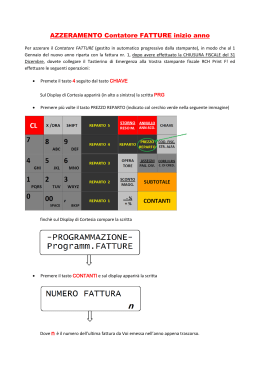
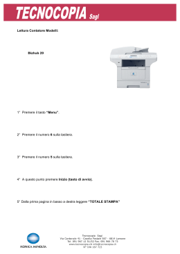
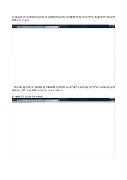
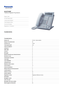
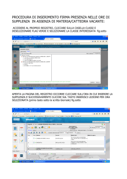
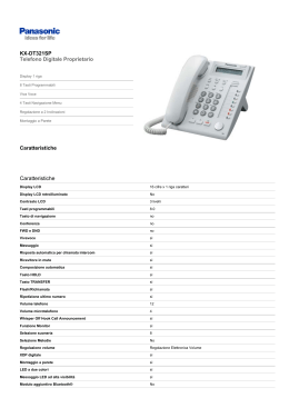
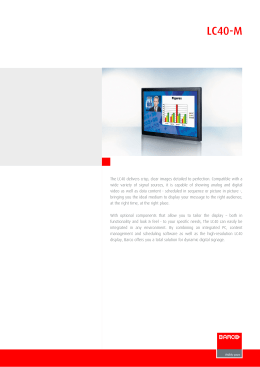
LIBRETTO ISTRUZIONI USER HANDBOOK Grazie della preferenza. Cordialmente, Nuova Simonelli S.p.a. 1 ITALIANO Complimenti, con l’acquisto del modello Lei ha fatto un’ottima scelta. L’acquisto di una macchina per caffè espresso professionale coinvolge diversi fattori di selezione: il nome dell’azienda produttrice, le specifiche funzioni della macchina, l’affidabilità tecnica, la possibilità di una pronta e adeguata assistenza, il costo. Lei certamente ha valutato tutto questo e poi ha deciso: scelgo il modello . Per noi, ha scelto il meglio e potrà verificarlo, caffè dopo caffè, cappuccino dopo cappuccino. Vedrà quanto sarà comodo, pratico ed efficiente lavorare con . Se è la prima volta che acquista una macchina Nuova Simonelli, benvenuto nell’alta caffetteria; se è già nostro Cliente, siamo molto lusingati della Sua fedeltà. ITALIANO CARATTERISTICHE TECNICHE E G F D B C A PESO NETTO PESO LORDO POT. TERMICA DIMENSIONI 2 2 Gruppi A B C D E F G 74 kg 80kg 4500 W 780 mm 635 mm 540 mm 315 mm 510 mm 135 mm 180 mm A B C D E F G 136 lb 176 lb 4500 W 301/4” 25” 21⅛” 123/16” 20” 5⅛” 71/16” 3 Gruppi A B C D E F G 88kg 98 kg 5000 W 1010 mm 865 mm 540 mm 315 mm 510 mm 135 mm 180 mm A B C D E F G 194 lb 216 lb 5000 W 39 5/16” 34” 21⅛” 123/16” 20” 5⅛” 71/16” 4 Gruppi A B C D E F G 104 kg 120 kg 5000 W 1240 mm 1095 mm 540 mm 315 mm 510 mm 135 mm 180 mm A B C D E F G 229 lb 264 lb 5000 W 485/16” 431/16” 21⅛” 123/16”” 20” 5⅛” 71/16” INDICE CARATTERISTICHE TECNICHE . . . . . . . . . 2 1. DESCRIZIONE Digit - V - Esse . . . . . . . . . . . . . . . . . . . . . . . 5 1.1 LISTA ACCESSORI . . . . . . . . . . . . . . . . . . . . . . . . . . . . 6 2. PRESCRIZIONI DI SICUREZZA . . . . . . . . . . 7 3. TRASPORTO E MOVIMENTAZIONE . . . . . 10 3.1 3.2 3.3 IDENTIFICAZIONE MACCHINA . . . . . . . . . . . . . . . . . 10 TRASPORTO . . . . . . . . . . . . . . . . . . . . . . . . . . . . . . . 10 MOVIMENTAZIONE . . . . . . . . . . . . . . . . . . . . . . . . . . 10 4. INSTALLAZIONE E OPERAZIONI PRELIMINARI . . . . . . . . . . . . 10 5. REGOLAZIONI DEL TECNICO QUALIFICATO . . . . . . . . . . . . . . 12 5.1 5.2 5.3 5.4 5.5 5.6 6. 6.1 6.1.1 6.1.2 6.1.3 6.2 6.3 6.4 6.5 RIEMPIMENTO MANUALE CALDAIA . . . . . . . . . . . . REGOLAZIONE PRESSOSTATO (Versioni V/Esse) / POMPA . . . . . . . . . . . . . . . . . . . . REGOLAZIONE ECONOMIZZATORE ACQUA CALDA . . . . . . . . . . . . SOSTITUZIONE BATTERIA OROLOGIO (Solo per versione Digit) . . . . . . . . . . . . . . . . . . . . . . SOSTITUZIONE DELLE PULSANTIERE . . . . . . . . . . GIORNALE ELETTRONICO . . . . . . . . . . . . . . . . . . . . 12 7. 7.1 7.2 7.3 7.4 7.5 8. 8.1 8.2 8.3 8.4 8.5 9. SELEZIONE ACQUA CALDA . . . . . . . . . . . . . . . . . . . 17 LANCIA VAPORE TEMPORIZZATA . . . . . . . . . . . . . . 17 PROGRAMMAZIONE AURELIA DIGIT . . . . 18 LEGENDA . . . . . . . . . . . . . . . . . . . . . . . . . . . . . . . . . . VISUALIZZAZIONE AURELIA DIGIT (Mod.UTENTE) . . . . . . . . . . . . . . . . . . . . . . . . . . . . . . PROGRAMMAZIONE Aurelia DIGIT (Mod. TECNICO) . . . . . . . . . . . . . . . . . . . . . . . . . . . . . PROGRAMMAZIONE AURELIA V . . . . . . . . . . . . . . . PROGRAMMAZIONE AURELIA ESSE . . . . . . . . . . . 18 18 19 26 29 PULIZIA . . . . . . . . . . . . . . . . . . . . . . . . . . . . 31 ARRESTO . . . . . . . . . . . . . . . . . . . . . . . . . . . . . . . . . . PULIZIA DELLA CARROZZERIA . . . . . . . . . . . . . . . . PULIZIA DELLE DOCCETTE INOX . . . . . . . . . . . . . . PULIZIA DEL GRUPPO CON L’AUSILIO DEL FILTRO CIECO . . . . . . . . . . . . PULIZIA DEI FILTRI E PORTAFILTRI . . . . . . . . . . . . 31 31 31 31 31 MANUTENZIONE . . . . . . . . . . . . . . . . . . . . . 32 9.1 RIGENERAZIONE DELLE RESINE DELL’ADDOLCITORE . . . . . . . . . . . . . . . . . . . . . . . . 32 10. MESSAGGI FUNZIONI MACCHINA Aurelia Digit . . . . . . . . . . . . . . 33 11. MESSAGGI FUNZIONI MACCHINA Aurelia V . . . . . . . . . . . . . . . . . 35 14 14 15 12. MESSAGGI FUNZIONI MACCHINA Aurelia V . . . . . . . . . . . . . . . . . 36 15 15 16 16 16 impianto elettrico . . . . . . . . . . . . . . . . 73 impianto IDRAULICO . . . . . . . . . . . . . . . . 76 12 13 13 13 13 UTILIZZO . . . . . . . . . . . . . . . . . . . . . . . . . . . 14 ACCENSIONE DELLA MACCHINA . . . . . . . . . . . . . . AURELIA DIGIT . . . . . . . . . . . . . . . . . . . . . . . . . . . . . AURELIA V / ESSE . . . . . . . . . . . . . . . . . . . . . . . . . . . AURELIA DIGIT / V / ESSE CON GIORNALE ELETTRONICO (OPTIONAL) . . . . . . . . . . . . . . . . . . . CONFIGURAZIONE SELEZIONE . . . . . . . . . . . . . . . . PREPARAZIONE DEL CAFFE’ . . . . . . . . . . . . . . . . . . UTILIZZO DEL VAPORE . . . . . . . . . . . . . . . . . . . . . . . PREPARAZIONE DEL CAPPUCCINO . . . . . . . . . . . . 6.6 6.7 ITALIANO 3 4 ITALIANO DESCRIZIONE Digit - V - Esse 2 1 3 4 5 ITALIANO 1. 6 21 7 20 8 9 19 10 18 17 16 15 14 13 12 11 Fig. 1 LEGENDA 1 Manopola vapore 2 Display LCD (solo Digit) 3 Pulsanti funzione (solo Digit) 4 Pulsanti selezione 5 Pulsanti gruppo erogatore 6 Giornale elettronico (Optional) 7 Manopola vapore 8 Portafiltro 9 Targhetta dati 10 Lancia vapore manuale 11 Gruppo erogazione 12 Interruttore generale 13 Becco 2 caffè 14 Becco un caffè 15 Lancia vapore automatica (Optional nelle versioni V ed Esse) 16 Livello ottico 17 Manometro 18 Piede regolabile 19 Lancia vapore manuale 20 Lancia acqua calda 21 Scaldatazze elettrico (Scaldatazze a vapore optional) 5 ITALIANO 1.1 LISTA ACCESSORI A11 A03 A02 A06 A01 A07 A05 A08 A04 A09 A10 6 CODICE A01 A02 A03 A04 A05 A06 A07 A08 A09 A10 A11 DESCRIZIONE Tubo carico C\,” Tubo scarico vaschetta gruppi Ø 20 mm - l. 150 cm Tubo scarico piano lavoro Ø 25 mm - l. 150 cm Portafiltro Filtro doppio Filtro singolo Filtro cieco Molla Becco erogazione doppio Becco erogazione singolo Pressa caffè Fig. 2 2 GRUPPI 3 GRUPPI 4 GRUPPI 1 1 1 3 2 1 1 3 2 1 1 1 1 1 4 3 1 1 4 3 1 1 1 1 1 5 4 1 1 5 4 1 1 SICUREZZA Il presente libretto costituisce parte integrante ed essenziale del prodotto e dovrà essere consegnato all’utilizzatore. Leggere attentamente le avvertenze contenute nel presente libretto in quanto forniscono importanti indicazioni riguardanti la sicurezza di installazione, d’uso e manutenzione. Conservare con cura questo libretto per ogni ulteriore consultazione. aver tolto l’imballaggio assicu Dopo rarsi dell’integrità dell’apparecchio. In caso di dubbio non utilizzare l’apparecchio e rivolgersi a personale professionalmente qualificato. Gli elementi dell’imballaggio (sacchetti in plastica, polistirolo espanso, chiodi, ecc.) non devono essere lasciati alla portata dei bambini in quanto potenziali fonti di pericolo, né essere dispersi nell’ambiente. distribuzione elettrica. La targa è situata sul frontale della macchina in alto a destra. L’installazione deve essere effettuata in ottemperanza alle norme vigenti, secondo le istruzioni del costruttore e da personale qualificato. Il costruttore non può essere considerato responsabile per eventuali danni causati dalla mancanza di messa a terra dell’impianto. Per la sicurezza elettrica di questo apparecchio è obbligatorio predisporre l’impianto di messa a terra, rivolgendosi ad un elettricista munito di patentino, che dovrà verificare che la portata elettrica dell’impianto sia adeguata alla potenza massima dell’apparecchio indicata in targa. gli apparecchi alimentati a 220 Per 230V, la massima impedenza fornita dalla rete di alimentazione non deve superare gli 0,37ohm. macchina deve essere installata in Laaccordo alle normative sanitarie loca- li vigenti per gli impianti idraulici. Quindi per l’impianto idraulico rivolgersi ad un tecnico autorizzato. l'installazione del dispositivo Durante devono essere utilizzati i componenti e i materiali in dotazione al dispositivo stesso. Qualora fosse necessario l'utilizzo di altra componentistica, l'installatore deve verificare l'idoneità dello stesso ad essere utilizzato a contatto con l'acqua per consumo umano. deve eseguire i collega L'installatore menti idraulici rispettando le norme di igiene e sicurezza idraulica di tutela ambientale vigenti nel luogo di installazione. Quindi per l’impianto idraulico rivolgersi ad un tecnico autorizzato. PERICOLO DI INQUINAMENTO del dispositivo deve L'alimentazione essere effettuata con acqua idonea al Fig. 4 dovrà anche accertare Ichen particolare la sezione dei cavi dell’impianto Fig. 3 di collegare l’apparecchio Prima accertarsi che i dati di targa siano sia idonea alla potenza assorbita dall’apparecchio. È vietato l’uso di adattatori, prese multiple e prolunghe. Qualora il loro uso si rendesse indispensabile è necessario chiamare un elettricista munito di patentino. consumo umano conforme alle disposizioni vigenti nel luogo di installazione. L'installatore deve acquisire dal proprietario / gestore dell'impianto conferma che l'acqua rispetti i requisiti sopra indicati. apparecchio dovrà essere Questo destinato solo all’uso descritto in questo manuale. Il costruttore non può essere considerato responsabile per eventuali danni causati da usi impropri, erronei ed irragionevoli. rispondenti a quelli della rete di 7 ITALIANO 2. PRESCRIZIONI DI ITALIANO non è idoneo per l’uti L’apparecchio lizzo da parte dei bambini, persone con ridotte capacità fisiche, sensoriali o mentali, o carenti di conoscenze a meno che non sia data supervisione o istruzione. Le temperature massime e minime di immagazzinamento devono essere comprese nel range [-5,+50]°C. di funzionamento Ladevetemperatura essere compresa nel range [+5, +35]°C. Al termine dell'installazione, il dispositivo viene attivato e portato fino alla condizione nominale di lavoro lasciandolo in condizioni di “pronto al funzionamento”. Successivamente il dispositivo viene spento e tutto il circuito idraulico viene svuotato della prima acqua immessa in modo da eliminare eventuali impurità iniziali. In seguito il dispositivo viene nuovamente caricato e portato fino alle condizioni nominali di funzionamento. Dopo il raggiungimento dello stato di “pronto al funzionamento” si effettuano le seguenti erogazioni: • 100% del circuito caffè attraverso l'erogatore caffè ( per più erogatori si divida in uguale misura); • 100% del circuito acqua calda attraverso l'erogatore acqua ( per più erogatori si divida in uguale misura); • apertura di ciascuna uscita vapore per 1 minuto. Al termine dell'installazione sarebbe buona regola stilare un rapporto di quanto effettuato. In particolare: •non toccare l’apparecchio con mani o piedi bagnati; •non usare l’apparecchio a piedi nudi; ATTENZIONE PERICOLO DI SCOSSA ELETTRICA •non usare, prolunghe in locali adibiti a bagno o doccia; •non tirare il cavo di alimentazione, per scollegare l’apparecchio dalla rete di alimentazione; •non lasciare esposto l’apparecchio ad agenti atmosferici (pioggia, sole, ecc.); •non permettere che l’apparecchio sia usato da bambini, o da personale non autorizzato e che non abbia letto e ben compreso questo manuale. In fase di installazione la rete elettrica dovrà essere predisposta con un sezionatore che sezioni ogni fase. 8 lo. È severamente vietato intervenire. Rivolgersi esclusivamente a personale professionalmente qualificato. L’eventuale riparazione dei prodotti dovrà essere effettuata solamente dalla casa costruttrice o da centro di assistenza autorizzato utilizzando esclusivamente ricambi originali. Il mancato rispetto di quanto sopra può compromettere la sicurezza dell’apparecchio. l’elettricista munito All’installazione, di patentino dovrà prevedere un interruttore onnipolare come previsto dalle normative di sicurezza vigenti con distanza di apertura dei contratti uguale o superiore a 3 mm. evitare surriscaldamenti perico Per losi si raccomanda di svolgere per tutta la sua lunghezza il cavo di alimentazione. tecnico autorizzato deve, prima di Non ostruire le griglie di aspirazione Ileffettuare qualsiasi operazione di e/o di dissipazione in particolare manutenzione, spegnere l'interruttore della macchina e aprire il sezionatore i fase. le operazioni di pulizia attenersi Per esclusivamente a quanto previsto nel seguente libretto. dello scaldatazze. cavo di alimentazione di questo Ilapparecchio non deve essere sostitu- ito dall’utente. In caso di danneggiamento, spegnere l’apparecchio e per la sua sostituzione rivolgersi esclusivamente a personale professionalmente qualificato. apparecchi monofase con corren Glite superiore a 15A e gli apparecchi di un qualsiasi apparecchio L’uso elettrico comporta l’osservanza di alcune regole fondamentali. caso di guasto o di cattivo funzio Innamento dell’apparecchio, spegner- Fig. 5 trifase venduti senza spina sono collegati all’impianto di alimentazione elettrica direttamente tramite il cavo; non è possibile quindi, l’utilizzo di una spina. raccomanda di renderlo inoperante dopo aver staccato la spina, tagliare il cavo di alimentazione. ATTENZIONE PERICOLO DI INQUINAMENTO ATTENZIONE PERICOLO DI USTIONE che prima di effettuare Ricordare qualsiasi operazione di installazione, manutenzione, scarico, regolazione, l’operatore qualificato deve indossare i guanti da lavoro e le scarpe antinfortunistiche. disperdere la macchina nell’am Non massimo livello di disturbo sonoro biente: per lo smaltimento rivolgersi Ilemesso è inferiore ai 70db. ad un centro autorizzato o contattare il costruttore che darà indicazioni in merito. tubo alla connessione idrica se Ilsostituito non deve essere più riutilizzato. Fig. 6 ATTENZIONE PERICOLO DI INTOSSICAZIONE l’uso della lancia del vapore, Durante prestare molta attenzione e non met- tere le mani sotto di esso e non toccarla subito dopo l’uso. ATTENZIONE INFORMAZIONE AGLI UTENTI Ai sensi dell’ art. 13 del Decreto Legislativo 25 luglio 2005, n. 151 “Attuazione delle Direttive 2002/95/CE, 2002/96/ CE e 2003/108/CE, relative alla riduzione dell’ uso di sostanze pericolose nelle apparecchiature elettriche ed elettroniche, nonché allo smaltimento dei rifiuti”. Il simbolo del cassonetto barrato riportato sull’apparecchiatura indica che il prodotto alla fine della propria vita utile deve essere raccolto separatamente dagli altri rifiuti. L’ utente dovrà, pertanto, conferire l’ apparecchiatura giunta a fine vita agli idonei centri di raccolta differenziata dei rifiuti elettronici ed elettrotecnici, oppure riconsegnarla al rivenditore al momento dell’acquisto di una nuova apparecchiatura di tipo equivalente, in ragione di uno a uno. L’ adeguata raccolta differenziata per l’ avvio successivo dell’ apparecchiatura dimessa al riciclaggio,al trattamento e allo smaltimento ambientalmente compatibile contribuisce ad evitare possibili effetti negativi sull’ ambiente e sulla salute e favorisce il riciclo dei materiali di cui è composta l’ apparecchiatura. Lo smaltimento abusivo del prodotto da parte dell’ utente comporta l’ applicazione delle sanzioni amministrative di cui al D.Lgs.n.22/1997” (articolo 50 e seguenti del D.Lgs.n.22/1997). Fig. 7 9 ITALIANO si decida di non utilizzare Allorché più un apparecchio di questo tipo si ITALIANO 3. TRASPORTO E 3.3 MOVIMENTAZIONE MOVIMENTAZIONE ATTENZIONE PERICOLO DI URTO O SCHIACCIAMENTO 3.1 IDENTIFICAZIONE MACCHINA Per qualsiasi comunicazione con il costruttore Nuova Simonelli, citare sempre il numero di matricola della macchina. Fig. 8 3.2 TRASPORTO La macchina viene trasportata in pallett con più macchine dentro scatoloni assicurati al pallett con delle centine. Prima di procedere a qualsiasi operazione di trasporto o movimentazione, l’operatore deve: •indossare guanti e scarpe antinfortunistici ed una tuta con elastici alle estremità. Il trasporto del pallett deve essere effettuato con un mezzo di sollevamento adeguato (tipo muletto). 10 L’operatore durante tutta la movimentazione, deve avere l’attenzione che non ci siano persone, cose od oggetti nell’area di operazione. Sollevare lentamente il pallett a circa 30 cm da terra e raggiungere la zona di carico. Dopo aver verificato che non ci siano ostacoli, cose o persone, procedere al carico. Una volta arrivati a destinazione, sempre con un mezzo di sollevamento adeguato (es. muletto), dopo essersi assicurati che non ci siano cose o persone nell’area di scarico, portare il pallett a terra e movimentarlo a circa 30 cm da terra, fino all’area di immagazzinamento. ATTENZIONE PERICOLO DI URTO O SCHIACCIAMENTO Prima della seguente operazione verificare che il carico sia a posto e che con il taglio delle centine non cada. L’operatore con guanti e scarpe antinfortunistiche, deve procedere al taglio delle centine e allo stoccaggio del prodotto, in questa operazione consultare le caratteristiche tecniche del prodotto per vedere il peso della macchina da immagazzinare e potersi regolare di conseguenza. 4. INSTALLAZIONE E OPERAZIONI PRELIMINARI Una volta rimosso l’imballo e aver verificato l’integrità della macchina e degli accessori, procedere come descritto di seguito: •posizionare la macchina su un piano orizzontale; •assemblare i piedini di sostegno della macchina inserendo l’inserto all’interno del guscio cilindrico; •avvitare il piedino in gomma nella filettatura dell’inserto contenuto nel guscio; •avvitare tutto il gruppo assemblato nelle apposite sedi di alloggiamento dei piedini della macchina; •mettere in piano la macchina agendo sui piedini di regolazione; NOTA: la scanalatura del guscio deve essere rivolta verso l’alto, come indicato nella figura successiva. Fig. 9 In fase preliminare, dopo la messa in piano della macchina, si consiglia di installare un addolcitore (1), all’uscita della rete idrica, e di seguito un filtro a maglia (2). Questo non permette alle impurità, come sabbia, particelle di calcare in sospensione, ruggine ecc., di danneggiare le delicate superfici in grafite, garantendo una buona durata della ATTENZIONE La pressione della rete idrica raccomandata è [2,3] bar. ATTENZIONE Evitare strozzature nei tubi di collegamento. Verificare inoltre che lo scarico (3) sia in grado di eliminare gli scarti. 2 1 3 Fig. 10 LEGENDA 1 Addolcitore 2 Filtro a maglia 3 Scarico Ø 50 mm NOTA: All'inizio della attività giornaliera e comunque nel caso in cui vi siano pause maggiori di 8 ore bisogna procedere ad effettuare il ricambio del 100% dell'acqua contenuta nei circuiti utilizzando gli erogatori preposti. •per voltaggio V 230 / monofase NOTA: In caso di esercizi in cui il servizio è continuativo effettuare i ricambi di sopra descritti almeno con frequenza settimanale. ATTENZIONE PERICOLO DI SCOSSA ELETTRICA La macchina deve essere sempre protetta con un interruttore automatico onnipolare di adeguata potenza con distanza di apertura dei contatti uguale o superiore a 3 mm. La Nuova Simonelli non risponde di alcun danno a cose o persone derivante dalla mancata osservanza delle vigenti norme di sicurezza. ITALIANO macchina. Dopo queste operazioni, provvedere ai collegamenti idraulici come illustrato nella seguente figura. Fig. 12 LEGENDA 1 Nero 2 Grigio 3 Marrone 4 Blu 5 Gialloverde Prima di allacciare la macchina a una rete elettrica verificare che il voltaggio indicato sulla targhetta dati della macchina corrisponda a quello della rete. In caso contrario, effettuare i successivi collegamenti sulla base della linea elettrica a disposizione, come illustrato successivamente: •per voltaggio V 380 / 3 fasi +Neutro: NOTA: Per un buon funzionamento della macchina occorre che la pressione di rete non superi i 4 bar. In caso contrario, installare un riduttore di pressione a monte dell’addolcitore; il tubo in entrata dell’acqua deve avere un diametro interno non inferiore ai 6 mm. Fig. 11 11 ITALIANO 5. REGOLAZIONI nimento in modo automatico dell’acqua nella caldaia. DEL TECNICO QUALIFICATO 5.1 RIEMPIMENTO MANUALE CALDAIA NOTA: operazione da eseguire a macchina spenta. sono muniti di sonda Tutti i modelli di livello, per mantenere costante il livello di acqua all’interno della caldaia. E’ buona norma, al primo avviamento della macchina, riempire manualmente la caldaia per evitare che la resistenza elettrica si danneggi e che inserisca la protezione elettronica. Se questo dovesse accadere, è sufficiente spegnere la macchina e riaccenderla, per completarne il caricamento (vedi capitolo “MESSAGGI FUNZIONE MACCHINA - ERRORE LIVELLO”). Per effettuare il primo riempimento manuale, agire come descritto di seguito: •rimuovere la griglia del piano di lavoro; •agire sul rubinetto livello manuale “A”, per permettere l’ingrasso dell’acqua nella caldaia; •raggiunto il livello minimo, indicato dal livello ottico, chiudere il rubinetto ”A”; A •Agire sulla vite di regolazione della pompa per AUMENTARE (senso orario) oppure DIMINUIRE (senso antiorario) la pressione; 5.2 REGOLAZIONE PRESSOSTATO (Versioni V/Esse) / POMPA NOTA: operazione eseguibile anche a macchina accesa. Per modificare la pressione di esercizio della caldaia, quindi la temperatura dell’acqua, in funzione delle varie esigenze o delle caratteristiche del caffè utilizzato, agire come descritto di seguito: •rimuovere la griglia del piano di lavoro; •togliere la protezione in lamiera svitando le due viti laterali (A) come illustrato nella seguente figura; •La pressione impostata della pompa viene visualizzata nel settore inferiore del manometro. MIN Fig. 14 Fig. 13 12 Valore consigliato: 9 bar. A MIN •accendere la macchina, posizionando l’interruttore generale su “I”, in modo da attivare la sonda livello, che provvederà al mante- Fig. 16 MAX •agire sulla vite di regolazione della pompa per AUMENTARE (senso orario) oppure DIMINUIRE (senso antiorario) la pressione; MAX Valore consigliato: 1 - 1,4 bar (secondo il tipo di caffè). Fig. 15 Fig. 17 Al termine delle regolazioni, riposizionare la protezione in lamiera nell’apposito alloggiamento e fissarla con le quattro viti laterali; riposizionare la griglia del piano di lavoro. NOTA: operazione eseguibile anche a macchina accesa. Tutti i modelli sono equipaggiati di un miscelatore di acqua calda, il quale permette di regolare la temperatura di uscita dell’acqua e di ottimizzare il rendimento del sistema. Per regolare l’economizzatore acqua calda, agire sul pomello di registro come descritto di seguito: •svitare e rimuovere le quattro viti (A) di fissaggio del pannello situate sotto le leve vapore e acqua calda; •rimuovere il pannello; 5.4 SOSTITUZIONE BATTERIA OROLOGIO (Solo per versione Digit) La centralina elettronica delle versioni Digit è provvista di una batteria al litio per l’alimentazione dell’orologio con autonomia di circa tre anni, dopodiché può rendersi necessaria la sostituzione. In caso di stop prolungato della macchina, l’orologio può essere bloccato con la seguente procedura: •con la macchina spenta, il display visualizza: OFF •mantenere premuto il tasto per 5 sec.; il display visualizza: STOP OROLOGIO A Fig. 18 •ruotare il pomello di registro in senso ORARIO / ANTIORARIO per AUMENTARE / DIMINUIRE la temperatura dell’acqua calda; 5.5 SOSTITUZIONE DELLE PULSANTIERE Per un corretto funzionamento occorre, all’atto della sostituzione, personalizzare ogni scheda pulsantiera, agendo sui selettori posti sulla scheda (lato tasti), così come sotto indicato. GRUPPOsw1 sw1 sw1 sw1 sw1 sw1 sw1sw1 Gruppo 1 On Off Off Off On Off Off Off Gruppo 2 Off On Off Off Off On Off Off Gruppo 3 Off Off On Off Off Off On Off Gruppo 4 Off Off Off On Off Off Off On 5.6 GIORNALE ELETTRONICO Come optional, in ogni modello, è previsto un giornale elettronico programmabile con la tastiera data in dotazione. Per la programmazione seguire le indicazioni fornite nell’apposito manuale. L’orologio si riavvierà appena la macchina sarà collegata all’alimentazione elettrica. ATTENZIONE La sostituzione della batteria al litio deve essere eseguita SOLO dal Tecnico Specializzato. La Nuova Simonelli non risponde di alcun danno a cose o persone, derivanti da una mancata osservanza delle prescrizioni di sicurezza, descritte in questo manuale. Fig. 19 •al termine dell’operazione rimontare il pannello protettivo con le apposite viti. 13 ITALIANO 5.3 REGOLAZIONE ECONOMIZZATORE ACQUA CALDA ITALIANO 6. UTILIZZO ATTENZIONE L’operatore deve prima di iniziare la lavorazione, accertarsi di aver letto e ben compreso le prescrizioni di sicurezza di questo manuale. 6.1 ACCENSIONE DELLA MACCHINA In caso di manutenzione alla scheda elettronica, spegnere la macchina tramite l’interruttore generale esterno o scollegare il cavo di alimentazione. ACCENSIONE / SPEGNIMENTO MANUALE On - Off Automatico NON PROGRAMMATO 6.1.1 AURELIA DIGIT •Collegare la macchina alla presa elettrica e posizionare l’interruttore generale in posizione “I”. •Lo stato di macchina in funzione viene indicato dalla relativa spia: Fig. 20 NOTA: assicurarsi che l’interruttore generale sia sempre in posizione “I”. Lo stato di macchina in funzione viene indicato dalla relativa spia: ACCENSIONE:premere il tasto per 2 sec., il cicalino emette un bip, il display si illumina indicando la release della Eprom per circa 1 secondo. La centralina effettua l’autodiagnosi delle funzioni, tutti i tasti di selezione si illuminano. Terminata la diagnosi, sul display compare la scritta: RISCALDAMENTO •Sul display, non illuminato, compare la scritta: OFF NOTA:La macchina non è operativa, in quanto l’interruttore generale permette solo l’alimentazione della scheda elettronica. 14 ATTENZIONE Nel caso in cui l’autodiagnosi indichi anomalie o guasti, chiamare il centro di assistenza, l’operatore NON DEVE intervenire. SPEGNIMENTO:premere il tasto per 2 secondi la macchina si spegne e sul display è indicato: OFF On - Off Automatico PROGRAMMATO NOTA: assicurarsi che l’interruttore generale sia sempre in posizione “I”. Lo stato di macchina in funzione viene indicato dalla relativa spia: La macchina si ACCENDERA’ al primo orario di accensione programmato (vedi capitolo PROGRAMMAZIONE e paragrafo PROGRAMMAZIONE ON - OFF). La centralina effettua l’autodiagnosi delle funzioni, tutti i tasti di selezione si illuminano. Terminata la diagnosi, sul display compare la scritta: RISCALDAMENTO con giorno e ora. Raggiunta la temperatura di 110°C, la scritta riscaldamento scompare, sostituita da: MACCHINA PRONTA con giorno e ora. Raggiunta la temperatura di 110°C, la scritta riscaldamento scompare, sostituita da: MACCHINA PRONTA NOTA: tutti i tasti di selezione sono abilitati sin dalla fine della diagnosi. NOTA: tutti i tasti di selezione sono abilitati sin dalla fine della diagnosi. Nel caso in cui l’autodiagnosi indichi anomalie o guasti, chiamare il centro di assistenza, l’operatore NON DEVE intervenire. La macchina si SPEGNERA’ al primo orario di spegnimento programmato (vedi capitolo PROGRAMMAZIONE e paragrafo PROGRAMMAZIONE ON - OFF). NOTA: La macchina può essere accesa o spenta manualmente come indicato nel paragrafo precedente. 6.1.2 AURELIA V/ESSE SPEGNIMENTO:premere l’interruttore generale in posizione “O” per spengere la macchina e la relativa spia. 6.1.3 AURELIA DIGIT / V / ESSE CON GIORNALE ELETTRONICO (OPTIONAL) ACCENSIONE:collegare la macchina alla presa elettrica e premere l’interruttore “A” in posizione “I”, la macchina si accende. Premendo l’interruttore “B” in posizione “I” si accende il display luminoso a macchina spenta. ACCENSIONE:collegare la macchina alla presa elettrica e premere l’interruttore generale in posizione “I”. Lo stato di macchina in funzione viene indicato dalla relativa spia: 6.2 CONFIGURAZIONE SELEZIONE Impostare la funzione desiderata sui tasti a disposizione posti sopra i portafiltri (Vedi capitolo “descrizione”). Fig. 23 LEGENDA TASTI (Configurazione selezioni) 1 Caffè corto 2 Caffè corto 1 Caffè lungo 2 Caffè lungo Fig. 22 ATTENZIONE Nel caso in cui l’autodiagnosi indichi anomalie o guasti, chiamare il centro di assistenza, l’operatore NON DEVE intervenire. Continuo Fig. 21 ATTENZIONE Nel caso in cui l’autodiagnosi indichi anomalie o guasti, chiamare il centro di assistenza, l’operatore NON DEVE intervenire. 15 ITALIANO ATTENZIONE ITALIANO 6.3 PREPARAZIONE DEL CAFFE’ Sganciare il portafiltro e riempire di una o due dosi di caffè macinato a seconda del filtro utilizzato. NOTA:nelle fasi di pausa, lasciare il portafiltro innestato al gruppo affinchè rimanga sempre caldo. I gruppi di erogazione sono termocompensati a circolazione totale di acqua calda, per garantire la massima stabilità termica durante l’esercizio. 6.4 UTILIZZO DEL VAPORE 6.5 PREPARAZIONE DEL CAPPUCCINO Per ottenere la tipica schiuma immergere il beccuccio del vapore in fondo al recipiente pieno per 1/3 (preferibilmente a forma troncoconica). Aprire il vapore. Prima che il latte abbia raggiunto lo stato di ebollizione, spostare il beccuccio del vapore in superficie facendo sfiorare il latte con piccoli spostamenti in senso verticale. Alla fine dell’operazione pulire accuratamente la lancia con un panno morbido. ATTENZIONE PERICOLO DI USTIONE Fig. 24 Pressare il caffè con l’apposito pressino in dotazione, pulire dai residui di polvere di caffè il bordo anulare del filtro (per garantire una migliore tenuta e un’inferiore usura della guarnizione). Innestare quindi il portafiltro nel gruppo. Premere il pulsante caffè desiderato: 1 Caffè corto 2 Caffè corto 1 Caffè lungo 2 Caffè lungo Durante l’uso della lancia del vapore, prestare molta attenzione a non mettere le mani sotto di essa e non toccarla subito dopo. Per utilizzare il vapore è sufficiente tirare o spingere l’apposita leva (Fig. 25). Tirando completamente, la leva rimane bloccata nella posizione di massima erogazione, spingendo, il ritorno della leva è automatico. Le due lance vapore sono snodate, consentendo un più agevole utilizzo delle stesse. Fig. 25 Si attiva la pompa e si apre l’elettrovalvola del gruppo dando avvio all’infusione del caffè. L’ operazione è evidenziata dall’accensione del tasto premuto. 16 NOTA: L'utilizzo della lancia vapore deve essere sempre preceduta dall'operazione di spurgo della condensa per almeno 2 secondi o seguendo le istruzioni del costruttore. Fig. 26 6.7 LANCIA VAPORE TEMPORIZZATA ATTENZIONE PERICOLO DI USTIONE ATTENZIONE PERICOLO DI USTIONE Durante l’uso della lancia dell’acqua calda, prestare molta attenzione a non mettere le mani sotto di essa e non toccarla subito dopo. Durante l’erogazione del vapore, non toccare con le parti del corpo la lancia, quindi mantenerla sempre inclinata verso il basso sulla griglia porta tazza. Consente l’erogazione di acqua calda per preparare thè, camomilla e tisane. Posizionare sotto la lancia acqua calda un contenitore (vedi Fig. 1 posizione 20). Premere una volta sul pulsante selezione Consente l’erogazione del vapore per emulsionare il latte, oppure per riscaldare altri liquidi. Posizionare sotto la lancia vapore automatica (vedi Fig. 1 posizione 15) un contenitore adatto. Premere una volta sul pulsante selezione vapo- acqua calda . re . Assicurarsi che il pulsante stesso si illumini. Assicurarsi che il pulsante stesso si illumini. Dalla lancia acqua calda verrà erogata acqua per un tempo equivalente al valore programmato. Dalla lancia vapore automatico uscirà vapore Ripremerlo per interrompere l’erogazione. NOTA:L’erogazione dell’acqua calda può avvenire contemporaneamente a quella del caffè . ITALIANO 6.6 SELEZIONE ACQUA CALDA Nei modelli Digit e V è disponibile come optional la lancia con sonda di temperatura che rimane aperta fino a che la bevanda che si vuole riscaldare raggiunge la temperatura impostata. 17 ITALIANO 7. PROGRAMMAZIONE AURELIA DIGIT 7.2 VISUALIZZAZIONE AURELIA DIGIT (Mod. UTENTE) Per entrare nell’ambiente di visualizzazione in per 8 modalità utente premere il tasto secondi e attendere il primo segnale acustico. La macchina visualizzerà: 7.1 LEGENDA 1 CICL.AUT.PULIZIA 2 3 4 5 Fig. 27 CICLO AUTOMATICO DI PULIZIA •Sul display è visualizzato: 2 Tasto RESET per accendere e spegnere la macchina e per uscire dal menù. 3 4 Tasto CURSORI: scorrimento dei menù e incremento e decremento dei valori. Tasto ENTER: per accedere all’interno del menù. LISTA FUNZIONI VISUALIZZABILI (Mod. UTENTE) CICL.AUT.PULIZIA DOSI CONT.EROGAZIONI TOTALE TOTALE MACCHINA CONTEGGIO LAVAGGI •Premere lizzato: e sul display verrà visua- CICL.AUT.PULIZIA SELEZIONA •Il tasto centrale di ogni gruppo comincerà a lampeggiare. Inserire il filtro cieco (fig2 A07) nel portafiltro, aggiungere mezza dose di pulicaff e agganciare il portafiltro al gruppo sul quale si vuole procedere con il lavaggio automatico. E’ possibile effettuare il lavaggio anche in più gruppi contemporaneamente. per avviare il ciclo •Premere il tasto di pulizia automatico sul gruppo. Sul display comparirà: CICL.AUT.PULIZIA ¡L dove 1L indica che nel 1° gruppo è stato attivato il ciclo di lavaggio. Terminato il ciclo 18 tasto del gruppo selezionato torna a lampeggiare e sul display comparirà . RISCIACQUARE •Premere il tasto per visualizzare la funzione successiva o per uscire dalla visualizzazione. DOSI •Sul display è visualizzato: DOSI CICL.AUT.PULIZIA 1 Display LCD. 5 di 15 erogazioni da 5 secondi l’una, con una pausa fra le erogazioni di 10 secondi, il e tutti i tasti dose, •Premere il tasto acqua calda e vapore lampeggeranno. •Premendo uno dei tasti lampeggianti a display verrà visualizzato il corrispondente valore programmato. per tornare alla •Premere il tasto funzione precedente. per uscire dalla •Premere il tasto visualizzazione. CONTEGGIO EROGAZIONI •Sul display è visualizzato: CONT. EROGAZIONI e tutti i tasti dose, •Premere il tasto acqua calda e vapore lampeggeranno. •Premendo uno dei tasti lampeggianti a display verrà visualizzato il corrispondente contatore. per tornare alla •Premere il tasto funzione precedente. per uscire dalla •Premere il tasto visualizzazione. LISTA FUNZIONI PROGRAMMABILI (Mod. TECNICO) •Sul display è visualizzato: TOTALE •Il tasto caffè corto di ciascun gruppo lampeggerà e premendolo potrà essere visualizzato il numero di caffè eseguiti con quel dato gruppo. •Premere i tasti lizzare le altre funzioni. •Premere il tasto visualizzazione. per visuaper uscire dalla TOTALE MACCHINA •Sul display è visualizzato: TOTALE MACCHINA EROGAZ. xxx •Premere i tasti zare le altre funzioni. •Premere il tasto visualizzazione. per visualiz- Operazione eseguibile SOLO da Tecnico Specializzato. La regolazione da parte di Tecnici NON qualificati o di altre persone potrebbe invalidare la garanzia. per uscire dalla CONTEGGIO LAVAGGI •Sul display è visualizzato: CONTAT. LAVAGGI •Il tasto un caffè lungo di ciascun gruppo lampeggerà e premendolo potrà essere visualizzato il numero di cicli di lavaggio eseguiti per quel dato gruppo. per visualiz•Premere i tasti zare le altre funzioni. •Premere il tasto visualizzazione. CICL. AUT. PULIZIA PROGRAM. DOSI CONT. EROGAZIONI PROGRAMM. ON/OFF RISP. ENERGETICO PRO. SCALDATAZZE DATA/ORA TEMPO EROGAZIONE SETPOINT PRESS. STORICO ALLARMI MANUTENZIONE LINGUA TEMPERATURA REG. LUMINOSITA’ per uscire dalla 7.3 PROGRAMMAZIONE Aurelia DIGIT (Mod. TECNICO) Per entrare nell'ambiente di programmazioneMod. Tecnico: per almeno 10 •Premere il tasto secondi ed attendere il secondo segnale acustico. Il display visualizza: CICL.AUT.PULIZIA e successivamente: ITALIANO TOTALE PROGRAM. DOSI CICLO AUTOMATICO DI PULIZIA •Sul display è visualizzato: CICL.AUT.PULIZIA •Premere lizzato: e sul display verrà visua- CICL.AUT.PULIZIA SELEZIONA •Il tasto centrale di ogni gruppo comincerà a lampeggiare. Inserire il filtro cieco (fig2 A07) nel portafiltro, aggiungere mezza dose di pulicaff e agganciare il portafiltro al gruppo sul quale si vuole procedere con il lavaggio automatico. E’ possibile effettuare il lavaggio anche di più gruppi contemporaneamente. per avviare il ciclo •Premere il tasto di pulizia automatico sul gruppo. Sul display comparirà: CICL.AUT.PULIZIA ¡L dove 1L indica che nel 1° gruppo è stato attivato il ciclo di lavaggio. Terminato il ciclo di 15 erogazioni da 5 secondi l’una, con una pausa fra le erogazioni di 10 secondi, il tasto del gruppo selezionato torna a lampeggiare e sul display comparirà: RISCIACQUARE 19 ITALIANO •Svuotare il filtro ceco da eventuali residui di pulicaff e premere il tasto per avviare il ciclo di risciacquo nel gruppo o nei gruppi in cui è stato eseguito il lavaggio. Nel display la lettere R rimane fissa cosi come il . Terminato il ciclo di risciacquo tasto del gruppo o dei gruppi selezionati, nel display compare la scritta: MACCHINA PRONTA PROGRAMMAZIONE DOSI •Sul display è visualizzato: PROGRAM.DOSI •Premere lizzato: e sul display verrà visua- PROGRAM.DOSI SELEZIONA Tutti i tasti programmabili cominceranno a lampeggiare. •Premere il tasto caffè da programmare, il display visualizza: VOLUME C.C: Seguita dal valore già programmato dalla casa costruttrice. •Variare la dose, agendo con i pulsanti . •Premendo il tasto caffè da programmare, inizierà l’erogazione (nel frattempo tutti gli altri tasti si spegneranno). •Una volta raggiunta la dose desiderata preper arremere il tasto caffè continuo stare l'erogazione. •Sul display verrà visualizzato il nuovo valore 20 che sarà ancora possibile modificare con i . tasti •Premere il tasto per confermare la dose programmata. per annullare la •Premere il tasto programmazione. •Il tasto caffè programmato si spegne. Acqua calda •Premere il pulsante e assicurarsi che lo stesso si illumini. Sul display comparirà la scritta: PROGRAM. DOSI SEC. ACQ. X.X Il valore X.X è quello impostato. per variare Premere i tasti il tempo di fuoriuscita dell’acqua calda da versare. •Se si intende fare un nuovo campionamento . premere nuovamente il pulsante Inizia l’erogazione. Quando la dose desiderata è raggiunta premere di nuovo il pulsan. te •Sul display viene visualizzato il nuovo valore da noi impostato ancora modificabile . selezionando i tasti o passare ad una •Premere il tasto successiva selezione per concludere l’operazione. per annullare la •Premere il tasto programmazione. si spegne. Il pulsante Vapore temporizzato/temperatura •Premere il pulsante lo stesso si illumini. e assicurarsi che Nelle versioni con sonda di temperatura (optional) la centralina riconosce automaticamente la presenza della sonda e sul display comparirà la scritta: PROGRAM. DOSI TEMP. VAP. °C seguita dal valore già impostato dalla casa costruttrice. per variare Premere i tasti la temperatura che deve raggiungere la bevanda da riscaldare. Raggiunta tale temperatura si fermerà automaticamente l’erogazione del vapore. •Nella versione standard (senza sonda di sul temperatura) premendo il tasto display comparirà la scritta: PROGRAM. DOSI SEC.VAP. seguita dal valore già impostato dalla casa costruttrice. per Premere con i tasti variare il tempo di fuoriuscita del vapore da erogare. •Se si intende fare un nuovo campionamento . premere nuovamente il pulsante Inizia l’erogazione. Quando la dose desiderata è raggiunta premere di nuovo il pulsan. te •Sul display viene visualizzato il nuovo valore da noi impostato ancora modificabile . selezionando i tasti o passare a una • Premere il tasto successiva selezione per concludere l’operazione. per annullare la •Premere il tasto programmazione. si spegne. Il pulsante DOSI STANDARD •Quando il display visualizza: CONTEGGIO EROGAZIONE •Quando sul display viene visualizzato: •Sul display è visualizzato: TRASFERIME. DOSI SELEZIONA GRUPPI PROGRAM. DOSI SELEZIONA si ha la possibilità premendo il tasto di trasferire il valore delle dosi programmate agli altri gruppi. Sul display verrà visualizzato: TRASFERIME. DOSI SELEZIONA GRUPPI del a questo punto i tasti caffè continuo secondo, terzo e quarto gruppo lampeggeranno come in Fig. 28. uno alla •Selezionando il tasto continuo volta (il tasto da lampeggiante diventa a luce fissa), si trasferiscono i valori programmati del primo gruppo agli altri gruppi. CONT. EROGAZIONI intendiamo richiamare i valori delle dosi standard. DOSI STANDARD SELEZIONA GRUPPI A questo punto i tasti caffè continuo inizieranno a lampeggiare. •Selezionare uno o più tasti continui (il tasto/i selezionati rimarranno a luce fissa). Il tasto/i richiameranno i valori delle dosi standard ai gruppi selezionati. •Premere il tasto per confermare . Sul display viene visualizzato: per confermare. •Premere il tasto A questo punto sul display viene visualizzato: PROGRAM. DOSI SELEZIONA •Premere il tasto uscire senza confermare. o per o •Tutti i tasti erogazione cominciano a lampeggiare. Premendo uno dei tasti erogazione si visualizza il numero delle relative erogazioni effettuate. per 3 •Per azzerare premere il tasto secondi. NOTA:Il caffè continuo è conteggiato pari a un’erogazione. •Premere lizzato: e sul display verrà visua- TOTALE MACCHINA EROGAZ. XXXX per NOTA: tutte le selezioni possono essere programmate per un tempo massimo di erogazione di due minuti, dopodichè compare la scritta (lampeggiante) sul display: ERRORE sul display appa- TOTALE SELEZIONE SELEZIONA PROGRAM. DOSI SELEZIONA Fig. 28 •Premendo il tasto rirà: •Premere il tasto . Sul display viene visualizzato: •Premere il tasto uscire senza confermare. ITALIANO TRASFERIMENTO DOSI Questo valore indica il numero totale di erogazioni effettuate. per 3 •Per azzerare premere il tasto secondi. sul display appare: •Premendo il tasto CONTAT.LAVAGGI per accedere al conteggio dei lavaggi auto. matici premere •Nella macchina lampeggiano i tasti caffè , premendo il tasto del gruppo si lungo visualizza il numero di cicli di lavaggio effettuati. Mantenendo premuto il tasto per 3 secondi si azzera il contatore. 21 ITALIANO Dopo la Domenica, premendo ancora PROGRAM. ON/OFF un bip indica il passaggio alla pagina successiva. •Sul display è visualizzato: PROGRAM. ON-OFF RISPARMIO ENERGETICO (stand-by) •Premendo il tasto lizzerà: , il display visua- • Sul display è visualizzato: RISP.ENERGETICO LUNEDI’ ON 07:30 OFF 23.30 i valori di ON e OFF indicano l’ora di accensione e spegnimento. per passare ai •Premere giorni successivi o precedenti. Questa funzionalità consente alla macchina di entrare o meno in uno stato di STANDBY attivo, che permette di scegliere se spegnere completamente la macchina oppure mantenerla ad una pressione impostata (minore di quella d’esercizio). per variare l’orario pro•Premere grammato per l’accensione (la scritta ON 07:30 comincerà a lampeggiare). per variare •Utilizzare i tasti l’orario di accensione. •Premete lizzato: per confermare e per •Premere passare all’orario programmato per lo spegnimento (la scritta OFF 23:30 comincerà a lampeggiare). Dove la modalità XXX potrà essere selezio. nata tramite i tasti •Utilizzare i tasti l’orario di spegnimento. •Confermare, premendo per variare . •Per disabilitare l’accensione e lo spegnimento nel giorno di riposo settimanale, pre. mere Sul display verrà visualizzato: RIPOSO SETTIMAN. (per ripristinare, premere 22 ) e sul display verrà visua- RISP.ENERGETICO xxx I 4 modi di funzionamento sono: •OFF: durante lo STANDBY la macchina è spenta e a display e mostrata la scritta "OFF"; •STANDBY 0.10 bar: durante lo STANDBY la macchina mantiene una pressione pari a 0.10bar e a display (impostato a luminosità minima) è mostrata la scritta "BASSO CONSUMO"; •STANDBY 0.50 bar: durante lo STANDBY la macchina mantiene una pressione pari a 0.50bar e a display (impostato a luminosità minima) è mostrata la scritta "BASSO CONSUMO"; •STANDBY 0.80 bar: durante lo STANDBY la macchina mantiene una pressione pari a 0.80 bar e a display (impostato a luminosità minima) è mostrata la scritta "BASSO CONSUMO". Questo funzionamento si ha, sia nel caso di accensione/spegnimento manuale attraverso il , sia nel caso di accensione/spetasto gnimento automatico attraverso la programmazione ON/OFF. Se durante uno dei tre stati di standby attivo (0.10bar, 0,50bar, 0,80bar) viene premuto il tasto RES, la macchina si porterà nello stato di OFF. Una successiva pressione del tasto porterà la macchina nello stato di ON. Premere il tasto per confermare la modalità selezionata a display e tornare indietro. per tornare indietro Premere il tasto senza confermare. PROGRAMMAZIONE SCALDATAZZE •Sul display è visualizzato: PRO. SCALDATAZZE Nell’elenco delle funzioni nascoste programmabili (Vedi Pag. 27), sezione scalda tazze, è possibile selezionare una delle seguenti tipologie di scaldatazze: singolo (tradizionale), temperatura singola, temperatura doppia. si entra nel sottomenù. Premendo Scaldatazze Singolo •Sul display è visualizzato: PRO. SCALDATAZZE , il display visua- PRO. SCALDATAZZE ON XX OFF xx La scritta ON XX comincerà a lampeggiare, variare il tempo con i tasti di scaldatazze aperto (compreso tra 0 e 60 min). per confermare e per •Premere passare al tempo di scaldatazze OFF, compreso tra 0 e 60 min. NOTA:Programmando uno dei due valori ON/ OFF a 0 la funzione viene automaticamente esclusa. Quando lo scaldatazze è programmato, il lampeggia lentamente. pulsante •Premere il tasto pagina successiva. per passare alla Temperatura singola •Sul display è visualizzato: SCALDATAZZE SETPOINT xxx°C è possibile •Tramite i tasti diminuire e aumentare la temperatura nel range [40°C ÷ 80°C] / [104°F ÷ 176°F] . per confermare e passare •Premere alla funzione successiva. per tornare alla pagina •Premere precedente senza confermare. Temperatura Doppia •Confermare premendo il tasto •Sul display è visualizzato: SCALDATAZZE ™ SETPOINT xx°C è possibile •Tramite i tasti diminuire e aumentare la temperatura n.1 nel range [40°C ÷ 80°C] / [104°F ÷ 176°F]. per tornare alla pagina •Premere precedente senza confermare. per confermare e passare •Premere alla fase successiva ed il display visualizzerà: SCALDATAZZE ¡ SETPOINT xxx°C è possibile •Tramite i tasti diminuire e aumentare la temperatura n.2 nel range [40°C ÷ 80°C] / [104°F ÷ 176°F]. per confermare e passare •Premere alla funzione successiva. per tornare alla pagina •Premere precedente senza confermare. PROGRAMMAZIONE DATA/ORA •Sul display è visualizzato: DATA/ORA •Premendo il tasto lizzerà per esempio: , il display visua- LUNEDI 08:22 08 MAGGIO 2003 Le ore cominceranno a lampeggiare. •Variare le ore e i minuti utilizzando i tasti . . Una volta variati le ore e i minuti premere e variare il giorno, il nuovamente mese e l’anno utilizzando la procedura sopra descritta. per passare alla Al termine premere pagina successiva. PROGRAMMAZIONE TEMPO DI EROGAZIONE Il modello Aurelia Digit è dotato di un sistema elettronico in grado di controllare il tempo di erogazione dipendenti dalla macinatura del caffè. •Sul display è visualizzato: TEMPO DI EROGAZ. •Premendo il tasto lizzerà: il display visua- TEMPO DI EROGAZ. XXX sarà possibile Con i tasti selezionare XXX come: •NON ATTIVO (non verranno visualizzati i tempi di erogazione). •RIGA 1 (verranno visualizzati i tempi di erogazione nella riga 1). •RIGA 2 (verranno visualizzati i tempi di erogazione nella riga 2). •Premere per confermare e passare alla fase successiva. per tornare alla pagina •Premere precedente senza confermare. 23 ITALIANO •Premendo il tasto lizzerà per esempio: ITALIANO Se la visualizzazione del tempo di erogazione è attiva quando viene fatta partire una erogazione, tranne che con il Continuo, la riga inferiore del Display viene adibita alla visualizzazione del tempo di erogazione (o dei tempi se più gruppi stanno erogando). Ad ogni gruppo è riservata una zona della riga inferiore: la zona a sinistra è per il gruppo 1, quella di fianco per il gruppo 2 così via fino alla zona più a destra per il gruppo 4. Le varie zone sono separate da barre verticali; se un gruppo non sta erogando la zona viene lasciata vuota, Di seguito è riportato un esempio: sono in erogazione il gruppo 1(è appena partito sono trascorsi 0 secondi), il gruppo 2 (sta erogando da 12 secondi), ed il gruppo 4 (sta erogando da 21 secondi). Zona riservata al tempo di erog. del gruppo 2 GIOVEDI 0 I 12 I Zona riservata al tempo di erog. del gruppo 1 Zona riservata al tempo di erog. del gruppo 3 12:00 I 21 Zona riservata al tempo di erog. del gruppo 4 Impostare il SETPOINT PRESS Il SETPOINT PRESS: permette di scegliere la pressione/temperatura di lavoro a regime. SETPOINT PRESS Premendo il tasto 24 il display visualizzerà: SETPOINT PRESS XX.XX BAR Premere di lavoro-press/temp. per regolare il punto VISUALIZZAZIONE STORICO ALLARMI •Premere per confermare e passare alla fase successiva. per tornare alla pagina •Premere precedente senza confermare. •Sul display è visualizzato: TABELLA PRESSIONE - TEMPERATURA AURELIA Digit •Premendo il tasto lizzerà: Bar 0,50 0,55 0,60 0,65 0,70 0,75 0,80 0,85 0,90 0,95 1,00 1,05 1,10 1,15 1,20 1,25 1,30 1,35 1,40 1,45 1,50 1,55 1,60 °C 110,5 111,5 112,5 113,5 114 115 115,5 116,5 117,5 118 119 119,5 120,5 121 122 112,5 123 124 124,5 125 126 126,5 127 °F 230,9 232,7 234,5 236,3 237,2 239 239,9 241,7 243,5 244,4 246,2 247,1 248,9 249,8 251,6 252,5 253,4 255,2 256,1 257 258,8 STORICO ALLARMI , il display visua- ERRORE 01 •Premendo il tasto si scorrono gli ultimi dieci allarmi memorizzati. Dopo il decimo allarme, premendo di nuovo il tasto si passa alla pagina successiva. PROGRAMMAZIONE MANUTENZIONE •Sul display è visualizzato: MANUTENZIONE •Premendo il tasto lizzerà: , il display visua- EROGAZIONI 10000 01 GENNAIO 2005 •Utilizzare i tasti per impostare entrambi i valori. per confermare. •Utilizzare il tasto Raggiunto il limite impostato di erogazioni o raggiunta la data fissata per la manutenzione sul display comparirà la scritta: MANUTENZIONE SELEZIONE LINGUA •Sul display è visualizzato: LINGUA , sul display verrà •Premendo il tasto visualizzata la lingua già impostata. Scegliere la lingua desiderata utilizzando i . tasti •Premere per confermare e passare alla fase successiva. per tornare alla pagina •Premere precedente senza confermare. SCELTA UNITA’ DI MISURA TEMPERATURA •Sul display è visualizzato: TEMPERATURA •Premendo il tasto , il display visualizza: TEMPERATURA FAHRENEIT O TEMPERATURA CELSIUS •Con i tasti è possibile modificare l’unità di misura impostata. •Premere per confermare e passare alla fase successiva. per tornare alla pagina •Premere precedente senza confermare. REGOLAZIONE LUMINOSITA' TASTIERA •Sul display è visualizzato: PULSANTI DISPLAY In REG. LUMINOSITA’ premere i tasti 1 caffè lungo + del PRIMO & SECONDO gruppo per almeno 3sec per accedere al menù speciale. Ora i pulsanti hanno le seguenti funzioni: RESET (per uscire dal menu nascosto). parametri). REG.LUMINOSITA’ •Premendo il tasto visualizzato: Accedere alle funzioni nascoste Questo permette di accedere ad altre funzioni speciali. UP/DOWN (per cambiare i ENTER (per navigare il menu nascosto). , sul display verrà X Y •Con la scritta “pulsanti X” lampeggiante, scegliere il valore di luminosità desiderato da un valore minimo di 1 a un massimo di 6 . utilizzando i tasti . •Confermare premendo •Il valore della luminosità “display Y” lampeggia e utilizzando i tasti è possibile impostare la luminosità della scritta “display Y” da un minimo di 1 ad un massimo di 3. •Premere per confermare e passare alla fase successiva. per tornare alla pagina •Premere precedente senza confermare. Elenco funzioni nascoste programmabili Autolivello: con pompa - senza pompa ( UP/DOWN per cambiare). Sens. autolivello: 1 - 2 - 3 ( UP/DOWN per cambiare) Acqua calda: con pompa - senza pompa UP/DOWN per cambiare). ( Livello in erogazione: non attivo - attivo UP/DOWN per cambiare). ( Taratura della temperatura: -15 - 0 - 15 °C/F UP/DOWN per cambiare). ( Taratura della pressione: -200 - 0 - 200 mbar UP/DOWN per cambiare). ( Preinfusione: non attivo - attivo ( UP/DOWN per cambiare). Scaldatazze: unica - unica temp. - Doppia temp. UP/DOWN per cambiare). ( Taratura dell’orologio: -300 - 0 - 300 sec / mese UP/DOWN per cambiare). ( Collegamento seriale: attivo - non attivo 25 ITALIANO Per far scomparire la parola MANUTENZIONE occorrerà spostare la data in avanti oppure aumentare il numero dei caffè. ITALIANO ( UP/DOWN per cambiare). Meno gruppo: 0 - 1 - 2 - 3 ( DOWN per cambiare). UP/ Meno servito: 0 - 1 - 2 - 3 ( DOWN per cambiare). UP/ Collegamenti diretti Nello stato "macchina pronta" è possibile accedere direttamente alle impostazioni di seguito, invece di passare per il menu. Impostare la SETPOINT PRESS: + premere ENTER + UP per andare direttamente al menu di impostazione del SETPOINT PRESS(questo sarà bar o° C/° F dipenderà lo status vista sono stati). premere SU o GIÙ per spostare in alto e in basso il punto di lavoro. Premere per confermare e passare alla fase successiva. Unità di monitoraggio (°C/°F – bar) Tramite display è possibile visualizzare lo stato della caldaia o in pressione oppure in temperatura. Il passaggio da una modalità all’altra lo si effettua con il tasto del display. Nel caso della pressione, la visualizzazione sarà in bar, mentre nel caso della temperatura la visualizzazione sarà in gradi Celsius (°C) oppure in gradi Fahrenheit (°F). L’impostazione della visualizzazione in temperatura e la scelta della scala modificano anche la pagina di impostazione del setpoint. Infatti, scegliendo la modalità temperatura, il setpoint verrà visualizzato in gradi Celsius o Fahrenheit a seconda della scelta della scala. 26 ON OFF STAND-BY (modalità di risparmio energetico) Questo permette di ruotare in tre modalità di lavoro. •Premere uno dei pulsanti erogatori (vedi figura): Premere RESET per 3 sec per accendere spegnere mettere in stand-by la macchina. •L’erogazione ha inizio, una volta raggiunta la quantità desiderata premere il tasto continuo 7.4 PROGRAMMAZIONE AURELIA V PROGRAMMAZIONE DOSI Per entrare negli ambienti di programmazione, operare come descritto: NOTA:Operazione eseguibile a macchina accesa. •Per entrare nello stato di programmazione dosi di ogni gruppo è necessario premere per 5 sec. il tasto erogazione continua del primo gruppo. •I tasti erogazione cominceranno a lampeggiare. •L’accesso alla programmazione del primo gruppo abilita anche l’impostazione dei parametri di funzionamento della macchina. PROGRAMMAZIONE DOSI CAFFE’ Per programmare la dose di acqua relativo a uno dei tasti erogazione, procedere come segue: •Riempire con la giusta dose di caffè il portafiltro (il portafiltro può essere singolo o doppio, a seconda del tasto che si desidera programmare). •Immettere il portafiltro nel gruppo. . •L’erogazione si arresta e il tasto dose scelto si spegne (gli altri tasti continuano a lampeggiare). •Premere il tasto continuo per uscire dalla programmazione o continuare la programmazione di altri tasti dose. NOTA:Questa procedura è utilizzabile per tutti i gruppi della macchina a eccezione che venga effettuata un gruppo alla volta, gli altri gruppi possono continuare a operare normalmente. PROGRAMMAZIONE ACQUA CALDA •Entrare in programmazione secondo la relativa procedura. •Premere il tasto selezione acqua calda . •L’erogazione dell’acqua calda ha inizio. •Stabilire la dose di acqua calda desiderata e premere nuovamente il tasto . per uscire •Premere il tasto continuo dalla programmazione o continuare la programmazione di altri tasti selezione. Tecnico:Per attivare la pompa durante l'erogazione dell'acqua calda entrare in programmazione del primo gruppo, poi premere il tasto continuo del secondo gruppo. •Per modificare l'impostazione è sufficiente ; se il premere il tasto acqua calda tasto è spento, durante l'erogazione di acqua calda la pompa non viene attivata, se il tasto è acceso durante l'erogazione di acqua calda viene attivata la pompa. Tasto del secondo •Premere il tasto continuo gruppo per confermare l'impostazione. PROGRAMMAZIONE VAPORE TEMPORIZZATO •Entrare in programmazione secondo la relativa procedura. . •Premere il tasto selezione vapore •L’erogazione di vapore ha inizio. •Stabilire la dose di vapore desiderata e pre. mere nuovamente il tasto •Per uscire dalla programmazione o continuare la programmazione di altri tasti selezione, premere il tasto continuo del primo e del secondo tasti continuo gruppo. Come descritto in tabella, ad ognuno dei tasti erogazione è associato un valore, il 5 minuti 4 minuti 10 minuti 8 minuti 20 minuti 16 minuti 40 minuti •Entrare in programmazione del primo gruppo secondo la relativa procedura. •Premere il tasto erogazione continua del secondo gruppo (il tasto si illumina). del •Premere il tasto 1 caffè corto secondo gruppo. PROGRAMMAZIONE SCALDATAZZE AUTOMATICO . •I pulsanti erogazione del primo e del secondo gruppo segnalano rispettivamente il tempo di accensione e di spegnimento in modalità automatica mentre lampeggiano i 2 minuti ATTIVAZIONE POMPA AUTOLIVELLO . •Entrare in programmazione secondo la relativa procedura. •Premere il tasto selezione scaldatazze 1° GRUPPO 2° GRUPPO (tempo ON) (tempo OFF) NOTA:Se il tasto 1 caffè corto è illuminato, la pompa si attiva durante il livello. tasto erogazione continua gruppo. del primo NOTA:Le impostazioni viengono salvate anche se si esce direttamente dalla programmazione del primo gruppo. REGOLAZIONE LUMINOSITA’ TASTIERA •Entrare in programmazione del primo gruppo secondo la relativa procedura •Premere il tasto erogazione continua del secondo gruppo. •Il tasto erogazione 2 caffè lungo del secondo gruppo lampeggia. •Premere il tasto più volte per cambiare l’intensità della luce. NOTA:E’ possibile impostare al massimo cinque diversi livelli di luminosità. •Per memorizzare i valori impostati di luminosità, premere il tasto erogazione continua del secondo gruppo. •Per uscire dalla programmazione, premere il del primo tasto erogazione continua gruppo. NOTA:Le impostazioni vengono salvate anche se si esce direttamente dalla programmazione del primo gruppo. Se il tasto 1 caffè corto non è illuminato, la pompa non si attiva durante il livello. •Premere il tasto erogazione continua del secondo gruppo. In questo modo viene memorizzata l’impostazione della pompa selezionata. •Per uscire dalla programmazione, premere il 27 ITALIANO tempo di accensione dello scaldatazze è dato dalla somma dei valori dei tasti del primo gruppo illuminati. La stessa modalità di conteggio avviene per il tempo di spegnimento dello scaldatazze con i tasti del secondo gruppo. ITALIANO LANCIA VAPORE CON SONDA DI TEMPERATURA (OPTIONAL) •Accertarsi che la sonda di temperatura sia stata collegata alla centralina. •Il valore di temperatura può essere inserito per campionamento o manualmente e varia da un minimo di 50°C ad un massimo di 95°C. •Dopo essere entrati in programmazione del Manuale: •Dopo essere entrati in programmazione del 1° gruppo, premere il tasto vapore . I tasti del 1°gruppo e del 2°gruppo, indicano la temperatura partendo dal un valore minimo di 50°C. •Ad ogni tasto è associato un valore: Tasto del 2° grup1° gruppo, premere il tasto po. L’ingresso nel sottomenu è segnalato dall’accensione del tasto del 2° gruppo. del 2° •Tramite il tasto due caffè corti gruppo, si imposta la memorizzazione della temperatura del vapore per campionamento, tasto acceso, oppure manuale, tasto spento. •Premendo il tasto di memorizzazione. si cambia la modalità del 2° grup•Premere il tasto continuo po, per memorizzare la modalità di inserimento della temperatura. Campionamento: •Dopo essere entrati in programmazione del 1° gruppo, inserire un bricco con il latte e , esso uscirà premere il tasto vapore dalla lancia. •Premendo nuovamente il tasto vapore la centralina memorizza la temperatura raggiunta nel campionamento. (Se la temperatura del latte raggiunge la temperatura massima, l’erogazione del vapore si ferma e rimane impostato nella centralina il valore massimo). 28 1° GRUPPO 2° GRUPPO 1 °C 10 °C 2 °C 20 °C 4 °C - 8 °C - •Facendo la somma del valore associato a vari tasti illuminati si ottiene il valore della temperatura, partendo dal valore minimo di 50°C. •Se il tasto è acceso occorre sommare il valore di riferimento, se il tasto è spento no. •Premendo nuovamente il tasto vapore si memorizza il valore e si ritorna allo stato di programmazione generale. In questa modalità di programmazione non avviene l’erogazione. •Per uscire dalla programmazione e salvare il valore impostato, premere il tasto erogazione continua del 1° gruppo. Tecnico: •Nello stato di impostazione della temperatura vapore si può impostare un valore di offset, da -15°C a +15°C, per ottenere il valore corretto della temperatura. del 1° gruppo •Tenendo premuto il tasto viene visualizzato il valore dell'offset impostato: la modalità è la stessa usata per la temperatura di fine erogazione del vapore. •Tramite i tasti del 1° gruppo si rappresenta un valore compreso da 0 a 15 °C, il tasto del 2° gruppo segnala il segno dell'offset: se acceso si tratta di un valore NEGATIVO, se spento di un valore POSITIVO. Tasto 1° GRUPPO 2° GRUPPO 1 °C + o - °C 2 °C - 4 °C - 8 °C - •Rilasciando il tasto del 1° gruppo si memorizza il dato e si ritorna all’impostazione della temperatura vapore. PROGRAMMAZIONE DOSI STANDARD •Premere il tasto erogazione continua del primo gruppo e mantenerlo premuto per almeno 8 secondi, fino a quando i tasti erogatori lampeggianti del primo gruppo si spengono. •Le dosi standard sono illustrate nella tabella sottostante: . •Se si vuole eseguire il ciclo di risciacquo in un secondo momento è sufficiente spegnere la macchina: la scheda mantiene memorizzati i cicli di pulizia da terminare. •Alla successiva accensione, infatti, la scheda entrerà automaticamente nello stato di e pulizia gruppi, senza premere i tasti . 40 cc 60 cc 50 cc 85 cc 9 sec. 0 sec. NOTA:Un tempo di 0 secondi per l’acqua e per il vapore ne determina il funzionamento in continuo. COPIATURA DOSI: Questa operazione va effettuata singolarmente a ogni gruppo premendo il tasto erogazione del gruppo su cui si devono continua copiare le dosi e mantenerlo premuto per almeno otto secondi fino a quando i tasti lampeggianti si spengono. CICLO AUTOMATICO DI PULIZIA GRUPPI •Per entrare nello stato di pulizia automatica si deve spegnere la macchina e riaccenderla acqua mantenendo premuti i tasti calda e scaldatazze durante il Lamptest iniziale. Al termine del Lamp-test inizia, ed i tasti no a lampeggiare i tasti un caffè lungo di tutti i gruppi. •Premendo i tasti e per 2 secondi si esce dallo stato di pulizia nel caso in cui non ci siano cicli da terminare, altrimenti rimarranno lampeggianti i tasti dei gruppi in cui si deve ancora eseguire il ciclo di risciacquo. •Mantenendo i tasti e per altri 2 secondi si forza l'uscita dallo stato di pulizia azzerando l'informazione sui risciacqui da terminare. •Se il ciclo di pulizia viene completato il tasto del gruppo si spegne; se non ci sono altri risciacqui da seguire la scheda esce dallo stato di pulizia. 7.5 PROGRAMMAZIONE AURELIA ESSE PROGRAMMAZIONE DOSI Nella versione Aurelia Esse è possibile programmare solo la dose di acqua e vapore temporizzato. Per entrare nello stato di programmazione è necessario: •Premere per cinque secondi il tasto scaldatazze . del primo •I tasti selezione e il tasto gruppo cominciano a lampeggiare mentre gli altri tasti erogazione degli altri gruppi si spengono. ACQUA CALDA •Una volta entrati nello stato di programmasi attiva zione, premendo il tasto l'erogazione di acqua calda, raggiunta la e dose desiderata ripremere il tasto la centralina memorizza il tempo di erogazione impostato. VAPORE TEMPORIZZATO •Una volta entrati nello stato di programmasi attiva zione, premendo il tasto l'erogazione di vapore, raggiunta la dose e la desiderata ripremere il tasto centralina memorizza il tempo di erogazione impostato. 29 ITALIANO •E’ possibile impostare dei valori predetermnati per le quattro dosi del primo gruppo erogatore. Per fare ciò occorre: inizia il ciclo di lavag•Premendo il tasto gio del relativo gruppo. Terminato il ciclo di lavaggio si può effettuare il ciclo di risciacquo sullo stesso gruppo, ripremendo il tasto ITALIANO REGOLAZIONE LUMINOSITA’ TASTIERA •Entrare in programmazione secondo la relativa procedura. •Regolare l’intensità della luce dei tasti premendo più volte il tasto gruppo. del primo NOTA:Per uscire dalla programmazione pre. mere il tasto ATTIVAZIONE POMPA AUTOLIVELLO •Entrare in programmazione secondo la relativa procedura. •Premere e mantenere premuto il tasto del secondo gruppo. •Per impostare l'attivazione della pompa durante l'autolivello, occorre, dopo essere entrati nello stato di programmazione, mantenere premuto il tasto gruppo. Il tasto del secondo del secondo gruppo si accende del primo gruppo viene e tramite il tasto visualizzata l'impostazione della pompa: se è acceso la pompa funziona durante il livello, se è spento la pompa non si attiva durante l'autolivello. del primo gruppo è Premendo il tasto possibile modificare l'impostazione della pompa durante il livello. NOTA:Per uscire dalla programmazione pre. mere il tasto 30 PULIZIA 8.3 PULIZIA DELLE DOCCETTE INOX 8.1 ARRESTO Per arrestare la macchina bisogna ripremere l’interruttore generale e portarlo nella posizione O. Versione Aurelia DIGIT/V/ESSE Le doccette inox sono situate sotto i gruppi erogazione, come si vede in figura (30). Versione Aurelia DIGIT/V/ESSE Prima di effettuare qualsiasi operazione di pulizia, bisogna portare la macchina a stato energetico “O” (cioè interruttore macchina spento e sezionatore aperto). ATTENZIONE Non è possibile pulire l'apparecchio con getto d'acqua o immergendolo in acqua. ATTENZIONE Non utilizzare solventi, prodotti a base di cloro, abrasivi. Pulizia zona lavoro: togliere la griglia del pianolavoro sollevandolo anteriormente verso l’alto e sfilarlo, togliere il sottostante piatto raccogliacqua e pulire il tutto con acqua calda e detersivo. Pulizia carena: per pulire tutte le parti cromate utilizzare un panno morbido inumidito. La macchina è predisposta per il lavaggio del gruppo erogazione tramite detergente specifico in polvere. La macchina inizierà il ciclo di pulizia che consiste nel ricircolo di acqua calda intervallata da un tempo di attesa. E’ consigliabile effettuare il lavaggio almeno una volta al giorno con gli appositi detergenti. ATTENZIONE PERICOLO DI INTOSSICAZIONE Fig. 29 8.2 PULIZIA DELLA CARROZZERIA 8.4 PULIZIA DEL GRUPPO CON L’AUSILIO DEL FILTRO CIECO Fig.30 NOTA:Per la pulizia operare come descritto: • Svitare la vite posta al centro della doccetta. • Sfilare la doccetta e verificare che i fori non siano ostruiti. • In caso di ostruzioni pulire secondo descrizione (Paragrafo “PULIZIA DEI FILTRI E PORTAFILTRI). Si raccomanda di effettuare la pulizia delle doccette settimanalmente. Una volta tolto il portafiltro effettuare alcune erogazioni per eliminare eventuali residui di detergente. Per eseguire la procedura di lavaggio procedere come segue: 1) Sostituire il filtro con quello cieco del gruppo erogatore. 2) Mettervi all’interno due cucchiai di detergente specifico in polvere e immettere il portafiltro al gruppo. 3) Premere uno dei tasti caffè e arrestare dopo 10 sec. . 4) Ripetere l’operazione più volte. 5) Togliere i portafiltro ed effettuare alcune erogazioni. 8.5 PULIZIA DEI FILTRI E PORTAFILTRI Mettere due cucchiaini di detergente specifico in mezzo litro d’acqua calda e immetervi filtro e portafiltro (escluso il manico) per almeno mezz’ora. Dopodichè risciacquare in abbondante acqua corrente. 31 ITALIANO 8. ITALIANO 9. MANUTENZIONE NOTA:Durante la manutenzione / riparazione i componenti utilizzati devono garantire di mantenere i requisiti di igiene e sicurezza previsti per il dispositivo. I ricambi originali forniscono questa garanzia. NOTA:Dopo una riparazione o una sostituzione di componenti che riguardano parti a contatto con acqua e alimenti, deve essere effettuata la procedura di lavaggio indicata al punto 1.4 o seguendo le procedure indicate dal costruttore. 9.1 RIGENERAZIONE DELLE RESINE DELL’ADDOLCITORE Al fine di evitare la formazione di depositi calcarei all’interno della caldaia e degli scambiatori di calore è necessario che l’addolcitore sia sempre in perfetta efficienza. Occorre perciò effettuare regolarmente la rigenerazione delle resine ioniche. I tempi di rigenerazione vanno stabiliti in funzione della quantità di caffè erogati giornalmente e della durezza dell’acqua utilizzata. Indicativamente si possono rilevare dal diagramma riportato in Fig. 31. Fig. 31 32 Le procedure di rigenerazione sono le seguenti: 1) Spegnere la macchina e mettere un recipiente della capacità di almeno 5 litri sotto il tubo E (Fig. 32). Ruotare le leve C e D da sinistra verso destra; togliere il tappo svitando la manopola G e introdurre 1 Kg di sale grosso da cucina (Fig. 33). USCITA E Fig. 34 D Fig. 32 C C F C ENTRATA 2) Rimettere il tappo e riposizionare la leva C verso sinistra (Fig. 34), lasciando scaricare l’acqua salata dal tubo F finchè non ritorni dolce (circa 1/2 ora). 3) Riportare quindi la leva D verso sinistra (Fig. 35). G D D Fig. 33 Fig. 35 INDICAZIONI DISPLAY E TASTI ERRORE DIAGNOSI CAUSA EFFETTO SOLUZIONE ERRORE EROGAZIONE L’indicazione sul display Premere il tasto lampeggia così come il o uno dei tasti tasto “continuo” del rela. tivo gruppo. ERRORE DOSATORE Se entro i primi tre secondi dall’inizio erogazione, il dosatore non ha inviato gli impulsi programmati. Se l’erogazione non è interrotta manualmente si arriva al blocco di tempo limite (120 sec.). Premere il tasto o uno dei tasti . Se dopo 90 sec. di funzionamento della macchina il livello dell’acqua non viene ripristinato. L’indicazione sul display lampeggia. La pompa si disattiva. La resistenza e tutte le funzioni sono inibite. Spegnere la macchina e riaccenderla. Si riattiveranno le funzioni. Quando la temperatura della macchina supera i 130° C. L’indicazione sul display lampeggia, e la resistenza si disattiva. Il sistema si autoripristina non appena la temperatura scende sotto i 130°C. ERRORE PRESSIONE NOTA Al momento della dia- La macchina non riscalgnosi il sistema presenta da e tutte le funzioni delle anomalie sulle sono bloccate. eprom della centralina. Raggiunto il tempo limite di erogazione (120 sec.) il dosatore non ha inviato gli impulsi programmati. ERRORE LIVELLO ITALIANO 10. MESSAGGI FUNZIONI MACCHINA Aurelia Digit La caldaia è provvista di un termostato di sicurezza a riarmo manuale, se la resistenza non si ripristina chiamare un tecnico specializzato. 33 ITALIANO INDICAZIONI DISPLAY E TASTI ERR. SOVRACORR. MACINATURA FINE MACINATURA GROSSA 34 CAUSA Errato assorbimento dovuto al mal funzionamento di un carico della macchina. EFFETTO SOLUZIONE NOTA L’indicazione sul display Spegnere la macchina e lampeggia. chiamare un tecnico speLa pompa si disattiva. cializzato. La resistenza e tutte le funzioni sono inibite. La macchina rileva valori Tempo molto più lungo Cambiare grado di macidiversi da quelli imposta- di erogazione. natura e premere il tasto ti. o uno dei tasti . La macchina rileva valori Tempo molto più corto di Premere il tasto diversi da quelli imposta- erogazione. o uno dei tasti ti. . Lasciando la macchina nello stato di programmazione, dopo 10 min. dall’ultima selezione, il sistema ritorna alla configurazione precedente e il display indica il normale funzionamento. INDICAZIONI DISPLAY E TASTI + + ECC CAUSA EFFETTO SOLUZIONE Se entro i primi tre sec. dall’inizio dell’erogazione il dosatore non invia impulsi. Se lerogazione non è interrotta manualmente si arriva al blocco di tempo limite (120 sec.). Interrompere l’erogazione. Se dopo 90 sec. dall’inizio, con pompa inserita durante altolivello, a 180 sec. se è disabilitata, il livello non è stata ripristinata. Viene disattivata la Spegnere la macchina pompa, la resistenza e per almeno 5 sec. e riactutte le funzioni sono ini- cenderla. bite. ITALIANO 11. MESSAGGI FUNZIONI MACCHINA Aurelia V NOTA 35 ITALIANO 12. MESSAGGI FUNZIONI MACCHINA Aurelia ESSE INDICAZIONI DISPLAY E TASTI + 36 CAUSA + ECC Se dopo 90 sec. dall’inizio, con pompa inserita durante altolivello, a 180 sec. se è disabilitata, il livello non è stata ripristinata. EFFETTO SOLUZIONE Viene disattivata la Spegnere la macchina pompa, la resistenza e per almeno 5 sec. e riactutte le funzioni sono ini- cenderla. bite. NOTA Congratulations, By purchasing the you have made an excellent choice. The purchase of a professional espresso coffee-maker involves various elements of selection: the name of the manufacturing firm, the machine’s specific functions, its technical reliability, the option of immediate and suitable servicing, its price. You certainly evaluated all these factors and then made your choice: the model. We think you have made the best choice and after every coffee and cappuccino you will be able to assess this. You will see how practical, convenient and efficient working with is. If this is the first time you have bought a Nuova Simonelli coffee machine, welcome to high quality coffee-making; if you are already a customer of ours, we feel flattered by the trust you have shown us. ENGLISH Thanks of the preference. With best wishes, Nuova Simonelli S.p.a. 37 TECHNICAL CHARACTERISTICS ENGLISH E G F D B C A NET WEIGHT GROS WEIGHT POWER DIMENSIONS 38 2 Groups A B C D E F G 74 kg 80kg 4500 W 780 mm 635 mm 540 mm 315 mm 510 mm 135 mm 180 mm A B C D E F G 136 lb 176 lb 4500 W 301/4” 25” 21⅛” 123/16” 20” 5⅛” 71/16” 3 Groups A B C D E F G 88kg 98 kg 5000 W 1010 mm 865 mm 540 mm 315 mm 510 mm 135 mm 180 mm A B C D E F G 194 lb 216 lb 5000 W 39 5/16” 34” 21⅛” 123/16” 20” 5⅛” 71/16” 4 Groups A B C D E F G 104 kg 120 kg 5000 W 1240 mm 1095 mm 540 mm 315 mm 510 mm 135 mm 180 mm A B C D E F G 229 lb 264 lb 5000 W 485/16” 431/16” 21⅛” 123/16”” 20” 5⅛” 71/16” INDEX TECHNICAL CHARACTERISTICS . . . . . . . 38 1. DESCRIPTION Digit - V - Esse 7. ACCESSORIES LIST . . . . . . . . . . . . . . . . . . . . . . . . . . 42 2. SAFETY PRESCRIPTION . . . . . . . . . . . . . .43 TRANSPORT AND HANDLING . . . . . . . . . 46 8. 3. . . . . . . . . . . . . . . . 41 3.1 3.2 3.3 MACHINE IDENTIFICATION . . . . . . . . . . . . . . . . . . . . 46 TRANSPORT . . . . . . . . . . . . . . . . . . . . . . . . . . . . . . . . 46 HANDLING . . . . . . . . . . . . . . . . . . . . . . . . . . . . . . . . . 46 4. INSTALLATION AND PRELIMINARY OPERATIONS . . . . . . . . . . . . . . . . . . . . . . . 46 5. ADJUSTMENTS TO BE MADE BY A QUALIFIED TECHNICIAN ONLY . . . . . . . . 48 55 62 65 CLEANING . . . . . . . . . . . . . . . . . . . . . . . . . . 67 SWITCHING OFF THE MACHINE . . . . . . . . . . . . . . . CLEANING THE OUTSIDE OF THE MACHINE . . . . . CLEANING STAINLESS COFFEE-HOLDERS . . . . . . CLEANING THE UNIT WITH THE AID OF THE BLIND FILTER . . . . . . . . . . . . . . . . . . . . . . . . . . . . . . CLEANING FILTERS AND FILTER-HOLDERS . . . . . 67 67 67 67 67 MAINTENANCE . . . . . . . . . . . . . . . . . . . . . 68 RESIN AND SOFTENER REGENERATION . . . . . . . . 68 48 49 10. Aurelia Digit MACHINE FUNCTION MESSAGES . . . . . . . . . . . . . . . . . . . . . . . . 69 49 49 49 11. Aurelia V MACHINE FUNCTION MESSAGES . . . . . . . . . . . . . . . . . . . . . . . . 71 12. Aurelia Esse MACHINE FUNCTION MESSAGES . . . . . . . . . . . . . . . . . . . . . . . . 72 ELECTRIC SYSTEM . . . . . . . . . . . . . . . . . 73 PLUMBING SYSTEM . . . . . . . . . . . . . . . . . .76 FILLING BOILER MANUALLY . . . . . . . . . . . . . . . . . PRESSURE SWITCH (V/Esse models) / PUMP ADJUSTMENT . . . . . . . . . . . . . . . . . . . . . . . . HOT WATER ECONOMISER ADJUSTMENT . . . . . . CLOCK BATTERY REPLACEMENT (Only for the Digit version) . . . . . . . . . . . . . . . . . . . . PUSH-BUTTON PANEL REPLACEMENT . . . . . . . . ELECTRONIC DISPLAYS . . . . . . . . . . . . . . . . . . . . . 6. USE . . . . . . . . . . . . . . . . . . . . . . . . . . . . . . . 50 TURNING THE MACHINE ON . . . . . . . . . . . . . . . . . . AURELIA DIGIT . . . . . . . . . . . . . . . . . . . . . . . . . . . . AURELIA V/ESSE . . . . . . . . . . . . . . . . . . . . . . . . . . . . AURELIA DIGIT/V/ESSE WITH ELECTRONIC DIARY (OPTIONAL) . . . . . . . . . SELECTION CONFIGURATION . . . . . . . . . . . . . . . . MAKING COFFEE . . . . . . . . . . . . . . . . . . . . . . . . . . . . USING STEAM . . . . . . . . . . . . . . . . . . . . . . . . . . . . . . MAKING CAPPUCCINO . . . . . . . . . . . . . . . . . . . . . . HOT WATER SELECTION . . . . . . . . . . . . . . . . . . . . . TIMED STEAM NOZZLE . . . . . . . . . . . . . . . . . . . . . . 9. 54 54 9.1 5.1 5.2 5.3 5.4 5.5 5.6 6.1 6.1.1 6.1.2 6.1.3 6.2 6.3 6.4 6.5 6.6 6.7 8.1 8.2 8.3 8.4 8.5 AURELIA DIGIT PROGRAMMING . . . . . . . . 54 KEY . . . . . . . . . . . . . . . . . . . . . . . . . . . . . . . . . . . . . . . AURELIA DIGIT DISPLAY (USER Mode) . . . . . . . . . PROGRAMMAZIONE Aurelia DIGIT (TECHNICIAN Mode) . . . . . . . . . . . . . . . . . . . . . . . . . PROGRAMMING AURELIA V . . . . . . . . . . . . . . . . . PROGRAMMING AURELIA ESSE . . . . . . . . . . . . . . 48 50 50 51 51 51 52 52 52 53 53 ENGLISH 1.1 7.1 7.2 7.3 7.4 7.5 39 40 ENGLISH 1. DESCRIPTION Digit - V - Esse 2 1 3 4 5 6 21 7 20 ENGLISH 8 9 19 10 18 17 16 15 14 13 12 11 Fig. 1 LEGENDA 1 Steam knob 2 LCD Display (Digit only) 3 Functions buttons (Digit only) 4 Selections buttons 5 Delivery unit buttons 6 Electronic displays (Optional) 7 Steam knob 8 Filter-holder 9 Data plate 10 Manual steam nozzle 11 Delivery unit 12 Main switch 13 2 coffees spout 14 1 coffee spout 15 Automatic steam nozzle (Optional on V and Esse models) 16 Optical level 17 Pressure Gauge 18 Adjustable foot 19 Manual steam nozzle 20 Hot water nozzle 21 Electric cup-warmer (steam cup-warmer, optional) 41 1.1 ACCESSORIES LIST A11 A03 A02 A06 A01 ENGLISH A07 A05 A08 A04 A09 A10 42 CODE A01 A02 A03 A04 A05 A06 A07 A08 A09 A10 A11 DESCRIPTION Filling tube 3/8” Unit tub draining tube Ø 20 mm - l. 150 cm Worktop draining tube Ø 25 mm - l. 150 cm Filter-holder Double filter Single filter Blind filter Spring Double delivery spout Single delivery spout Coffee presser Fig. 2 2 GROUPS3 GROUPS4 GROUPS 1 1 1 3 2 1 1 3 2 1 1 1 1 1 4 3 1 1 4 3 1 1 1 1 1 5 4 1 1 5 4 1 1 2. SAFETY PRESCRIPTION This book is an integral and essential part of the product and must be given to the user. Read this book carefully. It provides important information concerning safety of installation, use and maintenance. Save it carefully for future reference. do not use the appliance, but consult a qualified technician. Packaging items which are potentially dangerous (plastic bags, polystyrene foam, nails, etc.) must be kept out of children’s reach and must not be disposed of in the environment. you must ensure that the Insizeparticular of the wiring cables is sufficient to absorb power input. The use of adapters, multiple sockets or extensions is strictly forbidden. If they prove necessary, call a fully qualified electrician. machine must be installed in The compliance with the local health standards in force for plumbing systems. Therefore, contact an authorized plumber. sumption and compliant with the regulations in force in the place of installation. The installation engineer needs confirmation from the owner/ manager of the system that the water complies with the requirements and standards stated above. Fig. 4 Before connecting the appliance make sure the rating plate data correspond with the mains. This plate is on the front panel at the top right hand side of the appliance. The appliance must be installed by qualified technicians in accordance with current standards and manufactur- supplied with the device itself. Should it be necessary to use other parts, the installation engineer needs to check their suitability for use in contact with water for human consumption. device needs to be supplied with The water that is suitable for human con- DANGER OF POLLUTION Fig. 3 installing the device, it is nec When essary to use the parts and materials appliances powered at 220 -230 V, For the maximum impedance from the mains must be no higher than 0.37 Ohm. The machine must be installed according to the local standards in force with regard to plumbing systems. For this reason, the plumbing connections must be carried out by a qualified technician. appliance must only be used as This described in this handbook. The manufacturer shall not be liable for any damage caused due to improper, incorrect and unreasonable use. appliance is not suitable for use This by children or persons with reduced physical, sensory or mental capabilities, or by persons with a lack of experience or knowledge, unless supervised or given instructions. maximum and minimum storage The temperatures must fall within a range of [-5, +50]°C. operating temperature must be The within the range of [+5, +35]°C. 43 ENGLISH unpacking, make sure the appli After ance is complete. In case of doubts, er’s instructions. The manufacturer is not liable for any damage caused due to failure to ground the system. For the electrical safety of the appliance, it is necessary to equip the system with the proper grounding. This must be carried out by a qualified electrician who must ensure that the electric power of the system is sufficient to absorb the maximum power input stated on the plate. ENGLISH the end of installation, the device is Atswitched on and taken to rated operat- ing conditions, leaving it in a state in which it is “ready for operation”. The device is then switched off and the whole hydraulic circuit is bled of the first lot of water in order to remove any initial impurities. The device is then refilled and taken to rated operating conditions. After reaching the “ready for operation” condition, the following dispensing operations are carried out: • 100% of the coffee circuit through the coffee dispenser (for more than one dispenser, this is divided equally); • 100% of the hot water circuit through the water dispenser (for more than one dispenser, this is divided equally); • opening of each steam outlet for 1 minute. At the end of installation, it is good practice to draw up a report of the operations. Basic rules must be observed when using any electric appliance. In particular: •do not touch the appliance when hands or feet are wet; •do not use the appliance when barefoot; (rain, sun, etc.); •do not let the appliance be used by children, unauthorised staff or staff who have not read and fully understood the contents of this handbook. During installation, the mains power system needs to be equipped with a disconnector switch to cut off each phase. performing any maintenance Before operations, the authorised service engineer must switch off the machine and open the phase disconnector. For all cleaning operations comply exclusively with the instructions given in this booklet. 44 •do not use the appliance when barefoot; •do not pull the supply cord out of the socket to disconnect it from the mains; •do not leave the appliance exposed to atmospheric agents accordance with the safety regulations in force and with 3 (0,12) or more mm (in) between contacts. dangerous overheating, Tomakeavoid sure the supply cord is fully uncoiled. not obstruct the extraction and/or Dodissipator grids, especially of the cup warmer. user must not replace the appli The ance supply cord. If the cord is damaged, switch off the appliance and have a qualified technician change the cord. appliances with current Single-phase above 15 A and three-phase appli- ances sold without plugs are directly wired to the mains power and therefore, it is not possible to use a plug. no longer using the appliance, we Ifrecommend making it inoperative; CAUTION RISK OF ELECTRIC SHOCK installation, the qualified electri For cian must fit an omnipolar switch in Fig. 5 breaks down or fails Iftotheworkappliance properly, switch it off. Any intervention is strictly forbidden. Contact qualified experts only. Repairs should only be made by the manufacturer or authorized service centres. Only original spare parts must be used. Failure to observe the above, could make the appliance unsafe. after removing the plug from the mains electricity, cut the power supply cable. CAUTION RISK OF POLLUTION CAUTION RISK OF BURNS OR SCALDING not dispose of the machine in the remind you that before carrying Doenvironment: We to dispose of the out any installation, maintenance, machine, use an authorised centre, or contact the manufacturer for relative information. unloading or adjustment operations, the qualified operator must put on work gloves and protective footwear. never be re-used. Fig. 6 CAUTION RISK OF INTOXICATION the steam nozzle with care and Use never place hands below the jet of steam. Do not touch the nozzle immediately after use. Fig. 7 INFORMATION TO THE USERS Under the senses of art. 13 of Law Decree 25th July 2005, n. 151 “Implementation of the Directives/ Guidelines 2002/95/CE, 2002/96/CE and 2003/108/CE, concerning the reduction of the use of dangerous substances in electric and electronic equipment, as well as the disposal of wastes“. The symbol of the crossed large rubbish container that is present on the machine points out that the product at the end of its life cycle must be collected separately from the other wastes. The user for this reason will have to give the equipment that got to its life cycle to the suitable separate waste collection centres of electronic and electrotechnical wastes, or to give it back to the seller or dealer when buying a new equipment of equivalent type, in terms of one to one. The suitable separate waste collection for the following sending of the disused equipment to recycling, the dealing or handling and compatible environment disposal contributes to avoid possible negative effects on the environment and on the people's health and helps the recycling of the materials the machine is composed of. The user's illegal disposal of the product implies the application of administrative fines as stated in Law Decree n.22/1997” (article 50 and followings of the Law Decree n.22/1997). 45 ENGLISH maximum noise disturbance The level is lower than 70db. the pipe connecting to the mains Ifwater is replaced the old pipe must CAUTION 3. TRANSPORT AND HANDLING CAUTION RISK OF IMPACT OR CRASHING 3.1 MACHINE IDENTIFICATION ENGLISH Always quote the machine serial number in all communications to the manufacturer, Nuova Simonelli. Fig. 8 3.2 TRANSPORT The machine is transported on pallets which also contain other machines - all boxed and secured to the pallet with supports. Prior to carrying out any transport or handling operation, the operator must: •put on work gloves and protective footwear, as well as a set of overalls which must be elasticated at the wrists and ankles. The pallet must be transported using a suitable means for lifting (e.g., forklift). 46 3.3 HANDLING During all handling operations, the operator must ensure that there are no persons, objects or property in the handling area. The pallet must be slowly raised to a height of 30 cm (11,8 in) and moved to the loading area. After first ensuring that there are no persons, objects or property, loading operations can be carried out. Upon arrival at the destination and after ensuring that there are no persons, objects or property in the unloading area, the proper lifting equipment (e.g. forklift) should be used to lower the pallet to the ground and then to move it (at approx. 30 cm (11,8 in) from ground level), to the storage area. CAUTION RISK OF IMPACT OR CRASHING Before carrying out the following operation, the load must be checked to ensure that it is in the correct position and that, when the supports are cut, it will not fall. The operator, who must first put on work gloves and protective footwear, will proceed to cut the supports and to storing the product. To carry out this operation, the technical characteristics of the product must be consulted in order to know the weight of the machine and to store it accordingly. 4. INSTALLATION AND PRELIMINARY OPERATIONS After unpacking, assess that the machine and its accessories unit are complete, then proceed as follows: •place the machine so that it is level on a flat surface; •assemble its supporting feet by inserting the insert into the cylindrical unit; •twist the rubber foot into the screw thread inside the unit; •screw the whole assembled unit into the allotted setting for the machine’s adjustable feet; •level the machine by regulating the adjustable feet; NOTE: the unit grooves have to face upwards, as shown in the following illustration. Fig. 9 It is advisable to install a softener (1) and then a mesh filter (2) on the external part of the plumbing system, during preliminaries and after levelling the machine. In this way impurities like sand, particles of calcium, rust etc will not damage the delicate graphite surfaces and durability will be guaranteed. Following these operations, connect the plumbing systems as illustrated in the following figure. IMPORTANT Recommended mains pressure for the water is [2.3] bar. WARNING 2 1 3 • for V 230 / monophase voltage NOTE: In case of use where service is continuous, make the above changes at least once a week. CAUTION RISK OF SHORT CIRCUITS The machine must always be protected by an automatic omnipolar switch of suitable power with contact openings of equal distance or more than 3mm. Nuova Simonelli is not liable for any damage to people or objects due to not observing current security measures. Fig. 12 KEY 1 Black 2 Grey 3 Brown ENGLISH Avoid throttling in the connecting tubes. Assess that the drain pipe (3) is able to eliminate waste. NOTE: At the start of the day’s activities and in any case, if there are any pauses of more than 8 hours, then it is necessary to change 100% of the water in the circuits, using the relevant dispensers. 4 Blue 5 Yellow-green Prior to connecting the machine to the electrical mains, assess that the voltage shown on the machine’s data plate corresponds with that of the mains. If it does not, carry out the connections on the basis of the available electrical line, as follows: Fig. 10 KEY 1 Softener 2 Mesh filter 3 Drain Ø 50 mm NOTE: For a correct functioning of the machine the water works pressure must not exceed 4 bars. Otherwise install a pressure reducer upstream of the softener; the internal diameter of water entrance tube must not be less than 6mm. • for V 380 / 3 phases voltage +Neutral: Fig. 11 47 5. ADJUSTMENTS ENGLISH TO BE MADE BY A QUALIFIED TECHNICIAN ONLY the level gauge which will automatically maintain the water level inside the boiler. 5.2 PRESSURE SWITCH (V/Esse models) / PUMP ADJUSTMENT 5.1 FILLING BOILER MANUALLY NOTE: this operation can be carried out while the machine is turned on. NOTE: this operation must be carried out with the machine turned off. To adjust the service pressure of the boiler, thus regulating the water temperature, according to the various functions and needs of the coffee desired, proceed as follows: • remove the worktop grid cover; • remove the protective metal sheet by unscrewing the two side screws (A) as shown in the following illustration; are equipped with a All models level gauge to keep the water level inside the boiler constant. When using the machine for the first time, it is advisable to fill the boiler by hand to avoid damaging the electrical resistor and turning on the electronic protection. If this should happen, just turn the machine off and then start it up again to complete its loading procedure (see chapter “MACHINE FUNCTIONS MESSAGE – LEVEL ERROR”). To fill the boiler manually for the first time, proceed as follows: • remove the worktop grid; • turn the manual “A” level tap so that water will enter the boiler; • once the maximum level has been reached, as indicated by the optical level, turn tap “A” off; A 48 Fig. 16 Advisable pressure: 9 bar. •The set pump pressure is shown on the lower part of the gauge. A MIN Fig. 14 • turn the pump registration screw, turning it clockwise to INCREASE and counter clock wise to DECREASE the pressure. MIN • switch the machine on by placing the general switch on “I”; this will activate •Turn the pump registration screw, turning it clockwise to INCREASE and counter clock wise to DECREASE the pressure. MAX MAX Fig. 13 Advisable pressure: 1 - 1,4 bar (according to the kind of coffee). Fig. 15 Fig. 17 Once the adjustment operation has been completed, screw the protective metal sheet back into its setting and replace the worktop grid cover. 5.3 HOT WATER ECONOMISER ADJUSTMENT NOTE: this operation can be carried out while the machine is turned on. The electronic control unit on the Digit models has a lithium battery to power the clock and this has approximately three years’ autonomy after which, it may be necessary to replace it. In case the machine has remained unutilised for a long time, the clock can be blocked by proceeding as follows: • with the machine off the display will read: • press the key for 5 seconds; the display will read: STOP CLOCK For correct functioning of the machine, personalising each button panel card at time of replacement is necessary; proceed as follows on the selectors placed on the card (on the key side). GROUP Group 1 Group 2 Group 3 Group 4 sw1 sw1 sw1 sw1 sw1 sw1 sw1sw1 On Off Off Off On Off Off Off Off On Off Off Off On Off Off Off Off On Off Off Off On Off Off Off Off On Off Off Off On OFF A 5.5 PUSH-BUTTON PANEL REPLACEMENT The clock will start up again as soon as the machine is plugged in once more. 5.6 ELECTRONIC DISPLAYS As an optional extra, every model can be provided with an electronic diary that can be programmed using the keypad supplied. To set, follow the instructions provided in this booklet. Fig. 18 • CLOCKWISE/COUNTER CLOCKWISE to INCREASE/DECREASE the hot water temperature; WARNING Replacement of the lithium battery must be carried out EXCLUSIVELY by Qualified Technician. Nuova Simonelli cannot be held liable for any damage to people or things due to non observance of the safety prescriptions described in this booklet. Fig. 19 • when the operation has been completed, screw the protective panel back on. 49 ENGLISH are equipped with a hot All models water mixer tap which adjusts the water temperature and optimises the system’s performance. To adjust the hot water economiser, turn the registration knob as follows: • unscrew the panel (A) situated below the steam and hot water levers; • remove the panel; • turn the registration knob. 5.4 CLOCK BATTERY REPLACEMENT (only for the Digit version) 6. USE MANUAL SWITCHING ON/OFF Before starting to use the appliance, the operator must be sure to have read and understood the safety prescriptions contained in this booklet. ENGLISH 6.1 TURNING THE MACHINE ON 6.1.1 AURELIA DIGIT • Plug the machine in and position the main switch on “I”. • The state of the machine will be shown by the signal: Automatic On/Off NOT PROGRAMMED NOTE: make sure that the general switch is always on the position “I”. The state of the machine will be shown by the signal: SWITCH ON:press the key for 2 seconds, the buzzer will beep, the display will light up to indicate the release of the EPROM for about 1 second. The control unit will start up an auto diagnosis cycle to check the functions, all the selection keys will light up.Once the check is completed the display will read: HEATING Fig. 20 •The unlit display will read: OFF with the day and time. When 110°C has been reached, the heating message will disappear and will be replaced by the words: MACHINE READY NOTE:The machine is not operative in that the main switch only supplies the electronic card. NOTE: on completion of the check up all the selection keys are activated. WARNING WARNING For electronic card maintenance, turn the machine off by means of the external main switch or disconnect the plug. 50 In case the auto diagnosis indicates error or malfunction, call an assistance centre; the operator MUST NOT intervene. POWER OFF: press the key for 2 seconds; the machine will turn off and the display will read: OFF Automatic On/Off PROGRAMMED NOTE: make sure that the general switch is always on the position “I”. The state of the machine will be shown by the signal: The machine will SWITCH ON at the first programmed switch-on time (see the section entitled PROGRAMMING at the paragraph PROGRAMMING ON - OFF). The control unit will perform an auto diagnosis of all functions and all of the selection keys will light up. Once the diagnosis is complete, the display will read as follows: HEATING with the date and time. Once the temperature of 110°C has been the word “Heating” will disappear to be replaced by: MACHINE READY NOTE: once the auto diagnosis has been completed all the keys are activated. WARNING In case the auto diagnosis indicates error or malfunction, call the assistance centre; the operator MUST NOT intervene. The machine will SWITCH OFF at the first time set for stopping the coffee maker (see chapter on PROGRAMMING and paragraph on PROGRAMMING ON – OFF). SWITCH ON: Plug the machine in and position the “A” switch on “I”; the machine will turn on. By pressing the “B” switch onto position “I” an illuminated display will turn on even when the machine is switched off. 6.2 SELECTION CONFIGURATION Set the desired function on the available keys placed above the filter-holders (see chapter “description”). Fig. 23 6.1.2 AURELIA V/ESSE SWITCH ON: BUTTONS KEY (Selection configuration) plug the machine in and position the main switch on “I”. The state of the machine will be shown by the signal: Fig. 22 1 small coffee 2 small coffees 1 long coffee 2 long coffees WARNING In case the auto diagnosis indicates error or malfunction, call the assistance centre; the operator MUST NOT intervene. Fig. 21 WARNING Continuous In case the auto diagnosis indicates error or malfunction, call the assistance centre; the operator MUST NOT intervene. SWITCH OFF: press the main switch into the “O” position to switch the machine and the signal off. 51 ENGLISH NOTE: the machine can be switched on or off manually as indicated in the previous paragraph. 6.1.3 AURELIA DIGIT / V / ESSE WITH ELECTRONIC DIARY (OPTIONAL) 6.3 MAKING COFFEE Unhitch the filter-holder and fill it with one or two doses of ground coffee depending on the filter used. NOTE:when in pause, leave the filter-holder inserted in the unit so that it will keep warm. To guarantee the utmost thermic stability during use, the delivery units are thermo-compensated with complete hot water circulation. ENGLISH 6.4 USING STEAM CAUTION RISK OF BURNS OR SCALDING Fig. 24 Press the coffee with the provided coffee presser, dust off any coffee residue from the rim of the filter (this way the rubber gasket will last longer). Insert the filter in its unit. Press the desired coffee button: 1 small coffee 2 small coffees 1 long coffee 2 long coffees By starting up the coffee brewing procedure the unit’s pump is activated and the unit’s solenoid valve is opened. By pressing it, the button will turn on and signal the operation 52 6.5 MAKING CAPPUCCINO To obtain the typical cappuccino foam, immerse the nozzle all the way into a container 1/3 full of milk (preferably cone-shaped). Turn on the steam. Before the milk starts to boil, pull the nozzle slightly up and lightly move it vertically across the surface of the milk. When you have completed the procedure, clean the nozzle carefully with a soft cloth. While using the steam nozzle, you must pay attention to not place your hands beneath it or touch just after it has been used. To use steam just pull or push the provided lever (Fig. 25). By pulling it completely the lever will hold a position of maximum delivery; by pushing it, the lever will automatically give way. The two steam nozzles are articulated to guarantee their easy use. Fig. 25 NOTE: Before using the steam wand, always bleed out any condensation for at least 2 seconds or according to the manufacturer’s instructions. Fig. 26 6.6 HOT WATER SELECTION CAUTION RISK OF BURNS OR SCALDING 6.7 TIMED STEAM NOZZLE CAUTION RISK OF BURNS OR SCALDING While steam is being delivered do not touch the nozzle with any part of the body, and have it always facing downwards towards the cup-holder grid. This nozzle delivers hot water to make tea or herb teas. Place a suitable container under the hot water nozzle (see Fig. 1, position 20). Press the hot water selection button once . It provides steam ejection to foam milk or to heat up other liquids. Place a suitable container (see Fig. 1 position 15) under the automatic steam nozzle. Press the steam selection button once . Make sure the button lights up. Make sure that the button lights up. Water will be delivered from the hot water nozzle for as long as the set time indicates. Steam will be ejected from the automatic steam nozzle. Press it again to arrest delivery. NOTE:Hot water can be delivered at the same time as coffee. As an optional on Digit and V models, it is possible to fit a wand with temperature probe, which stays open until the drink to be heated reaches the set temperature. ENGLISH While using the hot water nozzle, pay careful attention not to place your hands beneath it or touch it just after it has been used. 53 7. AURELIA DIGIT PROGRAMMING 7.2 AURELIA DIGIT DISPLAY (USER Mode) To enter the user mode display environment, key for 8 seconds and hold down the wait to hear the first acoustic signal. The machine will read: 7.1 KEY 1 ENGLISH AUTO.CLEAN.CYCLE 2 3 4 5 Fig. 27 AUTOMATIC CLEANING CYCLE •The display will show: selected unit key will begin to flash on and off again and the display will read. RINSE •Press the key to view the next functions or to quit the display mode. DOSES •The display will read: DOSES AUTO.CLEAN.CYCLE 1 LCD Display. 2 RESET key to turn the machine on and off and to exit menu. 3 4 CURSOR key: to scroll the menu and to increase and decrease values. 5 ENTER key: to access the menu. LIST OF DISPLAY FUNCTIONS (USER Mode) AUTO CLEAN CYCLE DOSES POURING COUNT TOTAL MACHINE TOTAL TOTAL WASHES •Press and the display will read: AUTO.CLEAN.CYCLE SELECT •The central key in each unit will begin to flash on and off. Insert the blind filter (fig 2 A07) into the filter-holder, add half a dose of PULICAFF and attach the filter-holder into the unit where you intend to carry out the automatic cleaning cycle. Carrying out a cleaning cycle in more than one unit at a time is possible. key to start the unit •Press the automatic cleaning cycle. The display will read: AUTO.CLEAN.CYCLE ¡L where 1L indicates that the cleaning cycle has been activated within the 1st unit. Once the cycle of 15 deliveries of 5 seconds 54 each, with a 10-second pause between each delivery, has been completed the key and all of the dose, •Press the hot water and steam keys will start to flash. •Pressing one of the flashing keys will show the corresponding programmed setting on the display. key to return to the previ•Press the ous function. •Press the key to quit the display mode. POURING COUNT •The display will read: DELIVERY COUNT key and all of the dose, •Press the hot water and steam keys will start to flash. •Pressing one of the flashing keys will show the corresponding counter on the display. key to return to the previ•Press the ous function. key to quit the display •Press the mode. TOTAL LIST OF PROGRAMMABLE FUNCTIONS (TECHNICIAN Mode) •The display will read: TOTAL •The short coffee key of each group will flash and when pressed, the machine will show the number of coffees poured with the given group. keys to view the key to quit the display MACHINE TOTAL •The display will read: MACHINE TOTAL DELIVE. xxx •Press the other functions. •Press the mode. keys to view the Operation to be carried out EXCLUSIVELY by a Qualified Technician. Adjustment by NON qualified technicians can invalidate the guarantee. key to quit the display WASH COUNT •The display will read: CLEANING COUNTER •The long coffee key for each group will flash and when pressed, the display will show the number of wash cycles carried out for that particular group. keys to view the •Press the other functions. key to quit the display •Press the mode. 7.3 PROGRAMMAZIONE Aurelia DIGIT (TECHNICIAN Mode) To enter the Technician Mode programming environment: key for at least 10 •Hold down the seconds and wait for the acoustic signal. The display will read: AUTO.CLEAN.CYCLE PROGRAM. DOSES AUTOMATIC CLEANING CYCLE •The display will read: AUTO.CLEAN.CYCLE •Press ENGLISH •Press the other functions. •Press the mode. AUTO.CLEAN.CYCLE DOSE PROGRAM. DELIVERY COUNT ON-OFF PROGRAM. ENERGY SAVING CUP-WARMER PRO. DATE/TIME POURING TIME SETPOINT PRESS. HISTORICAL ALARM MAINTENANCE LANGUAGE TEMPERATURE LIGHT ADJUST followed by: and the display will read: AUTO.CLEAN.CYCLE SELECT •The central key in each unit will begin to flash on and off. Insert the blind filter (fig 2 A07) into the filter-holder, add half a dose of PULICAFF and attach the filter-holder into the unit where you intend to carry out the automatic cleaning cycle. It is possible to wash more than one group at the same time. key to start the unit auto•Press the matic cleaning cycle. The display will read: AUTO.CLEAN.CYCLE ¡L where 1L indicates that the cleaning cycle has been activated within the 1st unit. Once the cycle of 15 deliveries of 5 seconds each, with a 10-second pause between each delivery, has been completed the selected unit key will begin to flash on and off again and the display will read. RINSE 55 •Eliminate any residues of PULICAFF from the blind filter and press the rinsing cycle starting up key of the unit or units where the cleaning cycle has been effected. The letter R will remain on the display like . Once the rinsing cycle of the the key selected unit or units has been completed, the display will read. ENGLISH MACHINE READY PROGRAMMING DOSES •The display will read: PROGRAM. DOSES •Press and the display will read: PROGRAM. DOSES SELECT All the programmable keys will start to flash on and off. •Press the coffee key you wish to program; the display will read: VOLUME C.C: Followed by the dose amount already set by the manufacturers. •Vary the dose, by pressing the buttons . •By pressing the coffee key you want to program, delivery will be started up (in the meantime all the other keys will turn off). •Once you have the required dose, press the to stop pouring. continuous coffee key 56 •The display will show the new dose amount which can still be changed by means of the . keys key to confirm the pro•Press the grammed dose. key to cancel program•Press the ming. •The programmed coffee key will switch off. Hot Water •Press the button and make sure that it lights up. The display will read: PROGRAM. DOSES SECONDS X.X The value X.X is the default setting. keys to vary Press the the hot water delivery time. •If a new sampling is desired press the button again.. Delivery starts. When the desired dose has . been reached press the button again •The display will show the new dose value set which can still be changed by pressing keys. the key or go on to a further •Press the selection to terminate the operation. •Press the key to cancel programming. The button will turn off. Timed steam •Press the lights up. button and make sure it In those models provided with a temperature probe (optional) the control unit automatically recognizes the presence of the probe and the display will read: PROGRAM. DOSES STEA.TEM. °C followed by the temperature set previously by the manufacturer. keys to vary the Press the temperature of the beverage you want to heat. When the desired temperature has been reached, the steam delivery will automatically stop. •In the standard version (without temperature the display probe), on pressing the will read: PROGRAM. DOSES STEA.SEC. followed by the amount already set by the manufacturers. keys to vary the Press the steam delivery time. •If a new sampling is desired press the button again. Delivery starts. When the desired dose has . been reached press the button again •The display will show the new value set which can still be changed by pressing the . key or go on to a further • Press the selection to terminate the operation. •Press the key to cancel programming. button will turn off.. The STANDARD DOSES TRANSFERRING DOSES •When the display reads: DELIVERY COUNT •When the display reads: PROGRAM DOSES SELECT •The display will read: DELIVERY COUNT DOSES TRANSFER SELECT GROUPS transferring the set dose to other units is key. possible by pressing the •Press the key. The display will read: DEFAULT SETING SELECT GROUPS at this point, the continuous coffee keys At this point, the continuous coffee keys of the second, third and fourth groups will flash as shown in Fig. 28. will begin to flash. •Select one or more continue keys (the key or keys selected will remain lit up). The key or keys will recall the selected unit’s standard doses. •Press the key to confirm. The display will read: PROGRAM DOSES SELECT •Press the or the without confirmation. Fig. 28 •Press the key to confirm. At this point the display will read: PROGRAM DOSES SELECT •Press the or the without confirmation. key to exit key to exit NOTE:all the selections can be programmed for a maximum of two minutes; after that time a flashing message will appear on the display saying: ERROR key the display will SELECTION TOTAL SELECT DOSES TRANSFER SELECT GROUPS (the key •Selecting the continuous key will stop flashing and remain lit) will transfer the values programmed for the first group to the other groups, one at a time. •By pressing the read: •All the delivery keys will start to flash on and off. By pressing one of the delivery keys the amount of the deliveries made will be visualised. key for 3 seconds to •Hold down the reset. NOTE:The continuous coffee equals one delivery. •Press the read: key and the display will MACHINE TOTAL DELIVE. XXXX This indicates the total amount of deliveries made. key for 3 seconds to •Hold down the reset. key the display will •By pressing the read: CLEANING COUNTER To access the automatic cleaning counter . press on the machine •The long coffee keys will begin to flash; when the group key is pressed, the display will show the number of wash cycles carried out. Hold down the key for 3 seconds to reset. 57 ENGLISH The display will read: we mean to recall the standard dose values. After the word SUNDAY, by pressing ON/OFF PROGRAM. again, a beep will signal that you have come to the following page. •The display reads: ON-OFF PROGRAM ENERGY SAVING (stand-by) ENGLISH •By pressing the izzerà: , il display visual- • The display will read: ENERGY SAVING MONDAY ON 07:30 OFF 23.30 where the ON and OFF values indicate when the machine will turn on and off. to change the day •Press forward and backward. to vary the programmed •Press starting up time (the message ON 07:30 will start to flash on and off). keys to vary the •Use the starting up time. to confirm and to go on to the •Press programmed switching off time (the message OFF 23.30 will start to flash on and off). •Use the switching off time. •Confirm by pressing keys to vary the . •To de-activate the on/off function on weekly . day-off, press The display will read: DAY OFF (to reinstate, press 58 ) This function allows the machine to enter an active STANDBY status, where it is possible to choose whether to switch off the machine completely or to keep it at a set pressure (lower than working pressure). •Press and the display will read: ENERGY SAVING xxx Here it is possible to select the XXX mode keys. using the The 4 operating modes are: •OFF: during STANDBY the machine is switched off and the display reads "OFF"; •STANDBY 0.10 bar: during STANDBY, the machine maintains a pressure of 0.10 bar and the display (set to minimum brightness) reads "LOW POWER USE"; •STANDBY 0.50 bar: during STANDBY, the machine maintains a pressure of 0.50 bar and the display (set to minimum brightness) reads "LOW POWER USE"; •STANDBY 0.80 bar: during STANDBY, the machine maintains a pressure of 0.80 bar and the display (set to minimum brightness) reads "LOW POWER USE". This type of operation is possible when switching the machine on/off manually using the key and when switching the machine on/off automatically using the ON/OFF programming function. If the RES key is pressed while the machine is in one of the standby conditions (0.10 bar, 0.50 bar, 0.80 bar), the machine switches to OFF. If the key is pressed again, the machine enters the ON mode. key to confirm the mode Press the selected from the display and go back. key to go back without conPress the firming. CUP-WARMER PROGRAMMING •The display will read: CUPWARMER PROG. In the cup warmer section of the list of programmable hidden functions (see page 61), it is possible to select one of the following types of cup warmer; single (traditional), single temperature, double temperature. will open the submenu. Pressing Single Cup Warmer •The display will read: CUPWARMER PROG. •Pressing will cause the display to read, for example: CUP-WARMER PROG. ON XX OFF xx The message ON XX will begin to flash; use keys to change the the cup warmer open time (from 0 to 60 min.). NOTE:Setting one of the two ON/OFF values to 0 will automatically bypass the function. When the cup warmer is programmed, the button will flash slowly. •Press the page. key to pass to the next Temperatura singola •The display will read: CUP-WARMER SETPOINT xxx°C keys, it is pos•Using the sible to increase or reduce the temperature within a certain range [40°C ÷ 80°C] / [104°F ÷ 176°F]. to confirm and pass to the •Press next step; the display will read: to return to the previous •Press page without confirming. •The display will read: CUP-WARMER SETPOINT ™ xx°C keys, it is possi•Using the ble to increase or reduce the temperature no.1 within a certain range [40°C - 80°C] / [104°F - 176°F]. to return to the previous •Press page without confirming. to confirm and pass to the •Press next step; the display will read: CUP-WARMER ¡ SETPOINT xxx°C keys, it is possi•Using the ble to increase or reduce the temperature no.2 within a certain range [40°C ÷ 80°C] / [104°F ÷ 176°F]. to confirm and pass to the •Press next step; the display will read: to return to the previous •Press page without confirming. DATE/TIME PROGRAMMING •The display will read: DATE/HOUR •By pressing the read for example: key, the display will MONDAY 08:22 08- MAG-03 Once the hours and the minutes have been again and vary the varied press day, the month and the year by using the same procedure as described above. to go on to the On completion press next page. PROGRAMMING THE POURING TIME The Aurelia Digit is equipped with an electronic system to control delivery times according to the coffee grinding fineness. •The display will read: GRINDING •When the play will read: key is pressed, the dis- DELIVERY TIME XXX keys, it is possible Using the to select XXX as: •NOT ACTIVE (pouring times will not be shown). •ROW 1 (pouring times will be shown in row 1). •ROW 2 (pouring times will be shown in row 2). •Press to confirm and pass to the next step. * to return to the previous •Press page without confirming. The times will start to flash on and off. 59 ENGLISH to confirm and pass to the •Press cup warmer OFF time (from 0 to 60 min.). •Vary the hours and the minutes by using the . key •Confirm by pressing the key. Double Temperature ENGLISH If the delivery time display is on when a delivery is started - unless with the Continuous function - the bottom line of the display will show the delivery time (or times if more than one unit is delivering). Each group has an area of the bottom line: the area on the left is for unit 1; the area alongside it is for unit 2 and so on, until the area on the far right, which is for unit 4. The different areas are separated by vertical bars; if a group is not delivering, the area is empty. Here below is an example: unit 1 is delivering (it has just started and 0 seconds have passed); unit 2 has been delivering for 12 seconds and unit 4 is delivering (it has been delivering for 21 seconds). Area reserved to the delivery time of unit 2 Area reserved to the delivery time of unit 3 THURSDAY 0 I 12 I Area reserved to the delivery time of unit 1 12:00 I 21 Area reserved to the delivery time of unit 4 Setting the Set Point press: The set poin point allows to chose the pressure/ temperature in the working status. SETPOINT PRESS When the will read: 60 key is pressed, the display SETPOINT PRESS XX.XX BAR Press press/temp point. to adjust the work- •Press to confirm and pass to the next step. to return to the previous page •Press without confirming. PRESSURE - TEMPERATURE TABLE AURELIA Digit Bar 0,50 0,55 0,60 0,65 0,70 0,75 0,80 0,85 0,90 0,95 1,00 1,05 1,10 1,15 1,20 1,25 1,30 1,35 1,40 1,45 1,50 1,55 1,60 °C 110,5 111,5 112,5 113,5 114 115 115,5 116,5 117,5 118 119 119,5 120,5 121 122 112,5 123 124 124,5 125 126 126,5 127 °F 230,9 232,7 234,5 236,3 237,2 239 239,9 241,7 243,5 244,4 246,2 247,1 248,9 249,8 251,6 252,5 253,4 255,2 256,1 257 258,8 HISTORICAL ALARM VISUALISATION •The display will read: FAULTS HISTORY •By pressing the will read: key, the display ERROR 01 •Pressing the key, allows you to scroll down the ten previous alarms saved in the memory. After the tenth alarm, by presskey again you can go on to ing the the next page. MAINTENANCE PROGRAMMING •The display will read: MAINTENANCE •By pressing the read: key, the display will DELIVE. 10000 01 GENNUARY 2005 •Use the keys to set both values. key to confirm. •Use the Once the set delivery limit or the set maintenance date have been reached, the display will visualize the message: MAINTENANCE To remove the MAINTENANCE message, move the date forward or increase the number of coffees. SELECTING THE DESIRED LANGUAGE •Press to modify the measures unit setted. •Press to confirm and pass to the next step. to return to the previous page •Press without confirming. •The display will read: LANGUAGE KEYBOARD LIGHTING ADJUSTMENT key to visualise the lan•Press the guage already set. Choose the desired lankeys. guage by using the •Press to confirm and pass to the next step. to return to the previous •Press page without confirming. TEMPERATURE UNITY MEASURE SELECTION •The display reads: TEMPERATURE •By pressing , the display will read: TEMPERATURE FAHRENEIT O TEMPERATURE CELSIUS KEYS DISPLAY RESET (to exit hidden menu). , key, the display will UP/DOWN (to change the ENTER (to surf the hidden menu). X Y •With the KEYS light X blinking, select the value of desired brightness choosing from a minimum value of 1 to a maximum of 6 by keys. using the •Confirm by pressing 1 long coffee + keys of the FIRST & SECOND group for at least 3 sec to open the special menu. Now the buttons are for: parameters). LIGHT ADJUSTMENT •By pressing read: In BRIGHTNESS ADJUST. mode, hold down the . •The temperature DISPLAY value Y blinks keys it is possible and with to set the display lighting Y from a minimum value of 1 to a maximum of 3. •Press to confirm and pass to the next step. to return to the previous page •Press without confirming. Programmable hidden functions list Self level: with pump - no pump ( UP/DOWN to switch). Self level sense: 1 - 2 - 3 ( DOWN to switch). UP/ Hot water: with pump - no pump ( UP/DOWN to switch). Level in delivery: not active - active ( UP/DOWN to switch). Temperature calibration: -15 - 0 - +15 °C/F UP/DOWN to switch). ( Pressure calibration: -200 - 0 - +200 mbars UP/DOWN to switch). ( Pre brewing: not active - active ( UP/DOWN to switch). Cup warmer: single - single temp. - double temp. UP/DOWN to switch). ( Clock calibration: -300 - 0 - +300 sec/month UP/DOWN to switch). ( Serial connection: active - not active ( UP/DOWN to switch). 61 ENGLISH •The display reads: Enter the hidden functions This allows to enter other special functions. Least group: 0 - 1 - 2 - 3 ( DOWN to switch). UP/ Least serve: 0 - 1 - 2 - 3 ( DOWN to switch). UP/ ENGLISH Direct links In "machine ready" state you can go direct to the settings below instead of surfing the menu. Setting the Temperature Point: + press ENTER + UP to go directly to the Setting Point menu (this will be bars or °C/°F depend on the status view you were). press UP or DOWN to move up and down the working Point. •Press next step. to confirm and pass to the MONITORING UNIT (°C/°F – BAR) The display can also show you the pressure or temperature status of the boiler; to pass from key on the one to the other, press the display. In the case of pressure, the reading will be shown in bar, while for temperature, it will be in degrees Celsius (°C) or Fahrenheit (°F). The display setting for the temperature can be chosen from the setpoint setting page. In fact, when choosing the temperature mode, the setpoint will be shown in degrees Celsius or Fahrenheit according to the chosen measurement. ON OFF STAND-BY (energy saving mode) This allows to rotate into the three working modes/statuses. •Press one of the delivery buttons (see illustration): Press RESET for 3 sec to switch on stand-by the machine status. •The delivery will start; once the desired amount has been reached, press the con- off 7.4 PROGRAMMING AURELIA V DOSE PROGRAMMING To access the programming units, proceed as follows: NOTE:the procedure can be carried out with the machine on. •To access the dose programming state of each unit press the first unit’s continuous key for 5 seconds. delivery •The delivery keys will begin to flash on and off. •Access into the first unit’s programming allows you to set the machine’s function parameters. COFFEE DOSE PROGRAMMING To program the relative water doses for one of the delivery keys, proceed as follows: •fill the filter-holder with the correct dose of coffee (the filter-holder can be single or double depending on the key you wish to program). •Insert the filter-holder into the unit. keys. tinuous •The delivery will stop and the chosen dose key will turn off (the other keys will continue to flash). •Press the continuous key to exit programming or to continue programming other dose keys.. NOTE:This procedure is usable on all the machine units except if carried out one at a time; the other groups can carry on normally. HOT WATER PROGRAMMING •Access the programming according to the relative procedure. •Press the hot water selection key •Hot water delivery will start. •Establish the desired hot water dose and press the key again . key to exit the •Press the continuous programming or to continue programming other selection keys. Technician: To enable the pump while hot water is being dispensed, enter the programming mode for the first dispensing group then press the continual button for the second group. 62 •To change the settings, it is sufficient to values of the first unit’s lit-up keys. The same counting method is used for the cup-warmer switching off time with the keys of the second unit. ; if the butpress the hot water button ton is not lit, the pump will not be enabled while hot water is being dispensed; if the button is lit while hot water is dispensed, the pump will be activated. Keys 2° GROUP (time OFF) 2 minutes 5 minutes 4 minutes 10 minutes • Access the programming according to the relative procedure. 8 minutes 20 minutes . •Press the steam selection key •Steam ejection will start. •Establish the desired dose of steam and 16 minutes 40 minutes for the sec•Press the continual button ond dispensing group to confirm the setting. TIMED STEAM PROGRAMMING press the key again . LEVELLING PUMP ACTIVATION •Press the continuous key to exit the programming or to continue programming other selection keys. •Access the programming of the first group according to the relative procedure. •Press the second unit continuous key (the key will light up). AUTOMATIC CUP-WARMER PROGRAMMING •Access the programming according to the relative procedure. •Press the cup-warming selection key . •The delivery keys of the first and second unit will respectively signal the allotted automatic switching on and off times while the continuous keys of the first and second units will flash on and off. As described in the chart, each delivery key has an associated value, the starting up time of the cup-warmer is given by adding up the •Press the second unit 1 small coffee key. NOTA:If the I small coffee key is lit up, the pump will start up during the level. If the 1 small coffee key is not lit up, the pump will not start up during the level. ADJUSTING KEYBOARD LIGHTING INTENSITY •Access the programming of the first group according to the relative procedure. •Press the second unit continuous delivery key. •The second unit 2 long coffees key will flash on and off. delivery •Press the key more than once to vary the light intensity. NOTE:You can set a maximum of five different degrees of light intensity. •To store the set light intensity values in the memory, press the second unit continuous delivery key. •To exit the programming, press the first unit . continuous delivery key NOTE:The settings will be saved even when exiting the first unit programming directly. •Press the second unit continuous key. In this way the selected pump setting is stored. •To exit the programming, press the first unit key. continuous 63 ENGLISH 1° GROUP (time ON) NOTE:The settings will be saved even when exiting the first unit programming directly. ENGLISH STEAM NOZZLE WITH TEMPERATURE PROBE (OPTIONAL) •Make sure the temperature probe is connected to the control unit. •The temperature value can be planned by sampling or manually depending by the types of memorization planned in the parameter setting section and value goes from a minimum of 50°C to a maximum of 95°C. •By pressing the key of the second group is possible to chose if you wont set the steam temperature value manually or by sampling. •When you enter in this part of the menu, the on. key of the second group is switched •By pressing the key of the second group, it is possible to change the way in which settings are stored to memory. •Press the continuous delivery key for the 2nd unit to memorise the temperature value input mode. Sampling: •After entering in the program of the first group, put a jag with milk under the steam key, the delivery wand and press the of steam will start. •By pressing again the key, or if it is reached the maximum temperature, the control board memorizes the temperature reached. 64 Manually: •After entering in the program of the first group, press the keys of the first group, keys of the first and second group show the temperature starting from a minimum value of 50°C. •At every key has an value: Keys 1° GROUP 2° GROUP 1 °C 10 °C 2 °C 20 °C 4 °C - Technician: •In this steam temperature setting is possible to plan the offset value, from -15°C to +15°C, to obtain the correct temperature value. •By pressing the key of the first group, is showed the offset value setted: the way to show is the same of the way to show the final steam temperature. •The keys of the first group show a value from 0 to 15°C, the key of the second group show the offset sign: •it is switched on the value is positive, if the key is switched off is negative. Keys 8 °C - •Sum together the value associated to the relevant lit key to a minimum value of 50°C to obtain the temperature setting. •If the key is lit, it is necessary to add the reference value, while it is not required if the key is not lit. key the value •By pressing again the is planned and the machine came back to the general programming. This way of setting doesn't use the delivery of steam. •To escape from the program and save the key of the setting, press the continuos first group. 1° GROUP 2° GROUP 1 °C + o - °C 2 °C - 4 °C - 8 °C - •By releasing the key of the first group, you memorize the value and came back to the steam temperature setting. STANDARD DOSE PROGRAMMING •Setting predetermined values for the four doses of the first delivery unit is not possible. To do so, you must: key. again the •If you want make the rinsing cycle in an other time it's enough to switch off the machine: the control board memorizes the cleaning cycles that you must end. With the next turn on, the control board will enter automatically in the cleaning cycle, without pressing the and 40 cc 60 cc 50 cc 85 cc 9 sec. 0 sec. NOTE:A time of 0 seconds for water and steam give way to their continuous functioning. DOSE COPYING This procedure must be carried out for each unit continuous individually by pressing the delivery key of the unit you desire to copy the doses onto and keep pressing it for at least 8 seconds, until the flashing delivery keys turn off. AUTOMATIC CLEANING CYCLE •To enter in the automatic cleaning cycle, you must switch off the machine and switch on the the machine holding pressing hot water and cupwarmer keys during the initial Lamp-test. At the end of the Lampkeys, and test, starts to blinking the the groups. keys. and keys for 2 •By pressing the seconds you escape from the cleaning cycle in case there are not cycles to end, otherkeys of the group, in that you wise the must finish the rinsing cycle, remain with blinking. and •By holding pressing the keys for other 2 seconds you force the escape from the cleaning cycle by resetting the rinsing cycle. 7.5 PROGRAMMING AURELIA ESSE DOSE PROGRAMMING In the Aurelia Esse version only the doses of water and timed steam can be programmed. To access the programming state you must: for five •press the cup-warming key seconds.. •The selection keys and the 1 long coffee key belonging to the first unit will start to flash on and off while the other delivery keys of the other units will turn off. HOT WATER •Once the programming state has been key, hot accessed, by pressing the water delivery will be activated; once the desired dose has been reached press the key again and the set delivery time will be stored in the control unit. •If the cleaning and the rinsing cycle is ended, the key of the group switch off; if there are no cycles to finish, the machine return ready. TIMED STEAM •Once in the programming mode, pressing the key will enable steam dispensing and once you have the required dose, press key again and the control unit will the store the set dispensing time to memory. (one long coffee) keys of each 65 ENGLISH •Press the first unit continuous delivery key and keep pressing it for at least 8 seconds, until the flashing delivery keys of the first unit turn off. •The standard doses are illustrated in the following table: key starts the cleaning •By pressing the cycle in the group selected. When the cleaning cycle is finished, is possible to begin the rinsing cycle in the same group, by pressing ADJUSTING LIGHTING INTENSITY KEYBOARD •Access programming according to the relative procedure. •Adjust the light intensity of the keys by ENGLISH pressing the first unit’s 1 long coffee key more than once. NOTE:To exit programming press the key.. ACTIVATING LEVELLING PUMP •Access programming according to the relative procedure. •Press and keep pressing the 1 long coffee key belonging to the second unit. •To set the activation of the pump during levelling, once the programming state has been keep the second unit key activated, pressed. The second unit key will light up and by means of the first unit key the pump setting will be visualized: if it is lit up the pump will function during levelling; if it is not lit up the pump will not be activated during levelling. By pressing the first unit key the pump setting during levelling can be modified. NOTE:to exit the programming press the key. 66 8. CLEANING 8.1 SWITCHING OFF THE MACHINE To switch the machine off press the main switch and set the machine to the O energy position. Aurelia Version DIGIT/V/ESSE 8.4 CLEANING THE UNIT WITH THE AID OF THE BLIND FILTER The stainless coffee-holders are situated under the delivery units, as shown in figure (30). The machine is pre-set for cleaning the delivery unit with a specific washing powder. The machine will initiate washing cycle which consists in the circulation of hot water followed by regular breaks. We recommend carrying out a washing cycle at least once a day with special cleansers. Aurelia Version DIGIT/V/ESSE CAUTION RISK OF INTOXICATION Fig. 29 8.2 CLEANING THE OUTSIDE OF THE MACHINE The machine must be set to “O” power (switch off and disconnector open) before any cleaning operations are performed. WARNING It is not possible to clean the machine using water jets or standing it in water. WARNING Do not use solvents, chlorine-based products or abrasives. Cleaning the work area: remove the worktop, lifting it up from the front and sliding it out. Remove the water collection dish underneath and clean everything with hot water and cleansers. Cleaning the bottom: To clean all the chromium-plated areas, use a soft, damp cloth. Fig.30 NOTE:To clean proceed as follows: • Turn the screw placed in the centre of the coffee-holder. • Slide the coffee-holder out and check that its holes are not obstructed but clean. • If obstructed, clean as described (Paragraph “CLEANING FILTERS AND FILTER-HOLDERS”) We recommend cleaning the coffeeholder once a week. Once the filter-holder has been removed, repeat delivery operations a few times to eliminate any cleanser residues. To carry out the washing procedure, proceed as follows: 1) Substitute the filter with the delivery unit blind filter. 2) Fill it with two spoonfuls of special cleanser powder and insert it into the unit filter-holder. 3) Press one of the coffee keys and halt it after 10 seconds. 4) Repeat the procedure several times. 5) Remove the filter-holder and carry our a few deliveries. 8.5 CLEANING FILTERS AND FILTERHOLDERS Place two spoonfuls of special cleanser in half a litre of hot water and immerse filter and filterholder (without its handle) in it leaving them to soak for at least half an hour. Then rinse abundantly with running water. 67 ENGLISH 8.3 CLEANING THE STAINLESS COFFEEHOLDERS 9. MAINTENANCE ENGLISH NOTE:During maintenance/repairs, the parts used must be able to guarantee compliance with the safety and hygiene requirements envisaged for the device. Original replacement parts can offer this guarantee. Regeneration procedures are as follows: 1) Turn the machine off and place a container large enough to contain at least 5 litres under tube E (Fig. 32). Turn levers C and D from left to right; take the cap off by unscrewing knob and fill with 1 Kg normal kitchen salt (Fig. 33). C C NOTE:After the repair or replacement of any components of parts that come into contact with food or water, it is necessary to carry out the washing procedure as described in point 1.4 or according to the manufacturer’s instructions. IN OUT F E D Fig. 34 Fig. 32 9.1 RESIN AND SOFTENER REGENERATION 3) Reposition lever D towards the left (Fig. 35). C To avoid scaling deposits in the boiler and in the heating exchangers, the softener must always be kept efficient. Therefore, the ionic resins must be regularly regenerated. Regeneration times are established according to the quantity of coffee delivered daily and the hardness of the water utilised. As an indication, regeneration times can be calculated on the basis diagram illustrated in Fig. 31. Fig. 31 68 2) Put the cap back on and reposition lever C moving it towards the left (Fig. 34) and allowing tube F to discharge the salty water until it has been eliminated and the water becomes fresh again (about half and hour). G D D Fig. 33 Fig. 35 10. Aurelia Digit MACHINE FUNCTION MESSAGES DISPLAY AND KEY INDICATIONS DELIVERY ERROR DOSER ERROR LEVEL ERROR PRESSURE ERROR EFFECT SOLUTION NOTES At the time of the diagno- The machine will not sis the system presents heat and all its functions faults within the control will be blocked. unit EPROM. On reaching delivery time limit (120 seconds) the doser doesn’t send out its set commands. The display indicator and Press the key or the ‘continuous’ key one of the keys belonging to the relative . unit will flash on and off. If the doser doesn’t send out its set commands within the first three seconds from delivery onset. If the delivery isn’t manually halted, the maximum time limit (120 sec) will be blocked. Press the key or one of the keys . If after 90 sec of machine functioning the water level is not reestablished. The display indicator will flash on and off. The pump is de-activated. The resistor and all the functions are halted. Turn the machine off and then turn it on again. All its functions will be re-activated. When the machine’s temperature is higher than 130°C. The display indicator will flash on and off and the resistor is de-activated. The system will be reestablished as soon as the temperature goes below 130°C. ENGLISH DIAGNOSIS OF ERROR CAUSE The boiler is provided with a manual refitting safety thermostat; if the resistor is not re-established, call a qualified technician. 69 DISPLAY AND KEY INDICATIONS ENGLISH OVERCURRENT ERR. FINE GRINDING COARSE GRINDING 70 CAUSE Incorrect electrical input caused by a malfunction in one of the machine charges. EFFECT SOLUTION NOTES The display reading will Switch off the machine flash. The pump will and send for a specialist switch off. The heating technical engineer. element and all other functions will be disabled. The machine registers A much longer delivery Modify grinding degree values different from the time. and press the key set values. or one of the keys . The machine registers A much shorter delivery Press the key or values different from the time. one of the keys set values. . By leaving the machine in the programming state, within 10 minutes from the last selection, the system will return to the previous configuration and the display will indicate its reestablishment of normal functioning. 11. Aurelia V MACHINE FUNCTION MESSAGES DISPLAY AND KEY INDICATIONS CAUSE + + ECC SOLUTION NOTES If the delivery is not halt- Interrupt the delivery. ed manually, the time limit (120 sec.) will be blocked. ENGLISH If the doser doesn’t send out its commands within three sec from the onset of delivery. EFFECT If within 90 sec. from The pump, the resistor Turn the machine off for onset, with pump insert- and all the functions will at least 5 sec. and then ed during the levelling, at be halted. switch it on again. 180 sec., if the level has not been re-established. 71 12. Aurelia Esse MACHINE FUNCTION MESSAGES ENGLISH DISPLAY AND KEY INDICATIONS + 72 + ECC CAUSE EFFECT SOLUTION If within 90 sec. from The pump, the resistor Turn the machine off for onset, with pump insert- and all the functions will at least 5 sec. and then ed during the levelling, at be halted. switch it on again. 180 sec., if the level has not been re-established. NOTES IMPIANTO ELETTRICO / ELECTRIC SYSTEM Aurelia Digit 19 17 13 4 8 7 11 10 9 16 14 15 6 12 18 1 2 5 3 Fig. 35 LEGENDA / KEY 1 2 3 4 5 6 7 MS Interruttore / Main Switch. R Relè / Relay. P Pressostato / Pressostat. PM Motore pompa / Pump Motor. HE Resistenza boiler / Heater ELEMENT. TE Termostato / Thermostat. EV2 Elettrovalvola gruppo 2 / Solenoid Valve unit 2. 8 EV1 Elettrovalvola gruppo 1 / Solenoid Valve unit 1. 9 LP Sonda livello / level Probe. 10 EV4 Elettrovalvola gruppo 4 / Solenoid Valve unit 4. 11 EV 3 Elettrovalvola gruppo 3 / Solenoid Valve unit 3. 12 EVHW Elettrovalvola miscelatore / Solenoid Valve mixer. 13 EVL Elettrovalvola livello \ Solenoid valve level 14 SPC Sensore pressione caldaia/ SPC Boiler pressure sensor 15 RS1 Resistenza scaldatazze 1 / Cup warmer 1 heating element 16 RS2 Resistenza scaldatazze 2 / Cup warmer 2 heating element 17 EVS Elettrovalvola sfiato / Breather solenoid 18 CRS Connettore relè statici / Static relay connector 19 Elettrovalvola / Solenoid Valve 73 IMPIANTO ELETTRICO / ELECTRIC SYSTEM Aurelia V 14 13 15 8 7 10 11 9 12 4 6 5 1 2 3 Fig. 35 LEGENDA / KEY 1 2 3 4 5 6 7 MS Interruttore / Main Switch. R Relè / Relay. P Pressostato / Pressostat. PM Motore pompa / Pump Motor. HE Resistenza boiler / Heater ELEMENT. TE Termostato / Thermostat. EV2 Elettrovalvola gruppo 2 / Solenoid Valve unit 2. 8 EV1 Elettrovalvola gruppo 1 / Solenoid Valve unit 1. 74 9 LP Sonda livello / Level Probe. 10 EV4 Elettrovalvola gruppo 4 / Solenoid Valve unit 4. 11 EV 3 Elettrovalvola gruppo 3 / Solenoid Valve unit 3. 12 TP Sonda temperatura / Temperature Probe. 13 EVHW Elettrovalvola miscelatore / Solenoid Valve mixer. 14 EVC Uscita scaldatazze / Cup-warmer output. 15 EVL Elettrovalvola livello / Solenoid Valve level. IMPIANTO ELETTRICO / ELECTRIC SYSTEM Aurelia ESSE 13 12 4 8 7 11 10 9 14 6 5 1 3 2 Fig. 35 LEGENDA / KEY 1 2 3 4 5 6 7 MS Interruttore / Main Switch. R Relè / Relay. P Pressostato / Pressostat. PM Motore pompa / Pump Motor. HE Resistenza boiler / Heater ELEMENT. TE Termostato / Thermostat. EV2 Elettrovalvola gruppo 2 / Solenoid Valve unit 2. 8 EV1 Elettrovalvola gruppo 1 / Solenoid Valve unit 1. 9 LP Sonda livello / level Probe. 10 EV4 Elettrovalvola gruppo 4 / Solenoid Valve unit 4. 11 EV 3 Elettrovalvola gruppo 3 / Solenoid Valve unit 3. 12 EVHW Elettrovalvola miscelatore / Solenoid Valve mixer. 13 EVC Uscita scaldatazze / Cup-warmer output. 14 EVL Elettrovalvola livello / Solenoid Valve level. 75 IMPIANTO IDRAULICO / PLUMBING SYSTEM 10 19 18 15 14 9 13 8 11 12 16 17 6 1 2 3 5 4 Fig. 36 LEGENDA / KEY 1 Rubinetto ingresso acqua / Water entrance faucet. 2 Pompa / Pump. 3 Valvola di ritegno / Check valve. 4 Valvola neplas / Neplas valve. 5 Dosatore volumetrico / Flowmeter. 6 Elettrovalvola di livello / Level solenoid valve. 7 Rubinetto livello manuale / Manual level faucet. 76 8 Livello acqua / Water level. 9 Gruppo erogatore / Delivery unit. 10 Pressostato / Pressostat. 11 Manometro doppia scala / Double scale gauge. 12 Scambiatore di calore / Heat exchanger. 13 Vapore / Steam. 14 Valvola di sicurezza cald. / Heater safety valve. 15 Valvola antirisucchio / Anti-suction valve. 16 Economizzatore acqua calda / Hot water economiser. 17 Decalcificatore / Water softener. 18 Sonda livello / L evel probe. 19 Scaldatazze a vapore (optional) / Steam cup-warmer (optional). NOTE / NOTES: ......................................................................................................................................................................................................................... ......................................................................................................................................................................................................................... ......................................................................................................................................................................................................................... ......................................................................................................................................................................................................................... ......................................................................................................................................................................................................................... ......................................................................................................................................................................................................................... ......................................................................................................................................................................................................................... ......................................................................................................................................................................................................................... ......................................................................................................................................................................................................................... ......................................................................................................................................................................................................................... ......................................................................................................................................................................................................................... ......................................................................................................................................................................................................................... ......................................................................................................................................................................................................................... ......................................................................................................................................................................................................................... ......................................................................................................................................................................................................................... ......................................................................................................................................................................................................................... ......................................................................................................................................................................................................................... ......................................................................................................................................................................................................................... NOTE / NOTES: ......................................................................................................................................................................................................................... ......................................................................................................................................................................................................................... ......................................................................................................................................................................................................................... ......................................................................................................................................................................................................................... ......................................................................................................................................................................................................................... ......................................................................................................................................................................................................................... ......................................................................................................................................................................................................................... ......................................................................................................................................................................................................................... ......................................................................................................................................................................................................................... ......................................................................................................................................................................................................................... ......................................................................................................................................................................................................................... ......................................................................................................................................................................................................................... ......................................................................................................................................................................................................................... ......................................................................................................................................................................................................................... ......................................................................................................................................................................................................................... ......................................................................................................................................................................................................................... ......................................................................................................................................................................................................................... Codice 31000310 Eprom 4.71 Ed. 05 del 01/2010 Nuova Distribution Centre LLC 6940Salashan PKWY BLDG A 98248 Ferdale, WA Tel. +1.360.3662226 Fax +1.3603664015 videoconf.+1.360.3188595 www.nuovasimonelli.it [email protected] Graphics and printing by: X TYPE ENGINEERING S.r.l. Via M. d’Antegiano, 6 62020 Belforte del Chienti Macerata Italy Tel. +39.0733.9501 Fax +39.0733-950242 www.nuovasimonelli.it E-mail: [email protected] La Nuova Simonelli si riserva di apportare tutte le modifiche ritenute necessarie.
Scarica