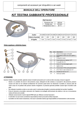
1) Installation and use must comply with the local
Regulations in force in the Country where the
nozzle is installed and used.
2) Feed the nozzle with filtered water only (10÷20 µm),
at a maximum temperature of 60°C.
3) In order to avoid dangerous, harmful overpressures, equip the system with a pressure-limiting
valve complying with the applicable Regulations.
4) The nozzle must be installed in a way that the
recoil force, created by the high pressure jet, is
aligned only the lance tube. If the lance is handoperated, it must be equipped with a compulsory
ON-OFF device that the user can easily operate,
with a safety lock for the OFF position and with a
shoulder support (it is strictly forbidden to use a
lance not equipped with the above-mentioned
devices). Avoid operating in situations of unstable,
or anyway, precarious balance, such as on ladders,
roofs etc. The high pressure jet creates a recoil
force (see point 5).
5) If the system as it is conceived implies the use of
a hand-operated lance, the recoil force must be
kept within the limits prescribed by the local Regulations in force and, in any case, must not
exceed 25 kgf.
This force can be calculated according to the
specifications, using the following formula:
F = 0.024·Q·√P
Wherein:
Q = capacity (l/min.)
P = pressure (BAR)
F = recoil force (Kgf) (1 Kgf= 9.81 N)
The resulting figure must be mentioned in the
operating instructions.
6) Before applying pressure to the nozzle, it is necessary to follow the steps listed below:
a - Check that the reachable parts are not: deformed, damaged or cracked.
b - Check that the nozzle is fastened correctly
onto the lance end.
c - Check that the nozzle components are fixed
correctly to each other with the following torque
settings:
NOZZLE BODY (pos. 1)
CONVEYOR NIPPLE (pos. 8) 120 Nm ±5%.
ADAPTER NIPPLE M-F (pos. 17) 70 Nm ±5%.
The above-mentioned positions correspond to
those shown in the spare parts catalogue.
INTERPUMP GROUP
VIA E. FERMI, 25
42040 S. ILARIO - REGGIO EMILIA (ITALY)
TEL. +39 - 0522 - 904311 • TELEFAX + 39 - 0522 - 904444
E-mail: [email protected]
http: //www.interpumpgroup.it
IMPORTANT: Do not use the ADAPTER NIPPLE
M-F G3/8-G1/2 with a pressure exceeding 500 bar
(7250 PSI).
®
For safety reasons, check the above-mentioned
points before operating the system for a whole
day work.
RMAX 750
INTERPUMP GROUP
GENERAL PUMP
OPERATING INSTRUCTIONS - MODE D’EMPLOI - BEDIENUNGSANLEITUNG
INSTRUCCIONES PARA EL USO - ISTRUZIONI D’USO
7) The use of the nozzle is allowed to qualified and
authorized staff only, who must be informed about
the nozzle features and instructions for use.
8) Before using the nozzle, wear protective clothes,
gloves, ear-shields and helmet with full- face cover,
in compliance with your local safety Regulations;
the installer and the user are liable for checking
the values of noise and vibration which the operator,
and persons possibly standing nearby, are subject
to (these depend on the type of work and of
installation); based on the applicable local regulations, maximum time of exposure and the precautions to be taken must be determined for both
subjects.
9) For safety and durability reasons, the system must
be started (ON) keeping the nozzle tipped 45°
downwards, so that the jet hits the ground first.
10) Before using the nozzle, make sure that persons,
animals or things that might be damaged by the
high pressure jet created by the nipple are not
within its radius of action.
11) Never direct the jet at persons or animals, even
though they are at a safe distance and even though
the nozzle is not under pressure.
TECHNICAL CHARACTERISTICS - CARATTERISTICHE TECNICHE
12) When the nozzle is not in use, engage the safey
lock in the OFF position; in addition to this, the
nozzle must be stored taking care that it is unreachable and cannot be used by unauthorized people,
by children and by elderly people.
MAX. PRESSURE
PRESS. MAX.
13) Before carrying out any inspection on the nozzle
and before storing it, make sure that the whole
circuit is totally released from possible residual
pressure, even though the system is not in function.
bar
P.S.I.
750
11000
MAX. VOLUME
PORTATA MAX.
G.P.M.
l/min.
(USA)
50
MAX. TEMPERATURE
TEMPERATURA MAX.
13.2
WEIGHT
PESO
LENGTH
LUNGHEZZA
INLET
ENTRATA
°C
°F
kg.
lbs
mm
In.
60
140
1.00
2.20
139
5.47
G1/2
(max. 500 bar)
G3/8
RC3/8
700
17.2
28.3
37.8
48.7
750
17.8
29.3
39.2
50.4
Flow
rate
Portata
(l/min.)
11000
4.73
7.78
10.40
13.39
Flow
rate
Portata
(G.P.M.)
NOZZLE CHART - TABELLA UGELLI
14) In case of disposal, do not scatter the material in
the environment; instead, take it to an authorized
disposal centre.
TYPE
TIPO
Nozzle
Ugello
15) In case of non-compliance with even just one of
the above-mentioned terms, stop working immediately and apply to the nearest Authorized Technical
Service; all maintenance operations must be carried
out by an Authorized Technical Service only; any
operation carried out by unauthorized people, as
well as the use of non original spare parts, can
result in situations of danger, moreover this causes
the voidness of the Legal Warranty.
RMAX750
G
J
N
R
TYPE
TIPO
Nozzle
Ugello
RMAX750
G
J
N
R
Cod. 10.0653.03 - 09/04 - 500
FOR A SAFE AND EFFECTIVE USE, COMPLY
STRICTLY WITH THE FOLLOWING INSTRUCTIONS:
100
6.5
10.7
14.3
18.4
2000
2.02
3.32
4.44
5.71
200
9.2
15.1
20.2
26.0
250
10.3
16.9
22.6
29.1
3000
2.47
4.07
5.43
6.99
300
11.3
18.5
24.8
31.9
4000
2.85
4.69
6.27
8.07
PRESSURE - PRESSIONE (bar)
350
400
450
500
550
12.2 13.0 13.8 14.5 15.2
20.0 21.4 22.7 23.9 25.1
26.8 28.6 30.3 32.0 33.5
34.4 36.8 39.0 41.1 43.2
PRESSURE - PRESSIONE (p.s.i.)
5000
6000
7000
8000
3.19
3.49
3.77
4.03
5.25
5.75
6.21
6.64
7.01
7.68
8.30
8.87
9.03
9.89
10.68
11.42
600
15.9
26.2
35.0
45.1
9000
4.28
7.04
9.41
12.11
650
16.6
27.3
36.5
46.9
10000
4.51
7.42
9.92
12.76
The flows in the shaded area exceed the reactive force limit of 25 kg / 55 lbs for manual work (hand held).
Le portate nell’area ombreggiata sono oltre il limite di 25 kg / 55 lbs della forza di reazione per il lavoro manuale.
1
2
3
4
6
7
PER UN UTILIZZO SICURO ED EFFICACE APPLICARE RIGOROSAMENTE LE ISTRUZIONI SOTTORIPORTATE:
8
1) Le modalità di installazione e utilizzo devono essere
conformi alle Normative vigenti nel paese di installazione e di quelle dove l’ugello viene utilizzato.
15 16 17
2) Alimentare l’ugello esclusivamente con acqua filtrata
(10÷20 µm), ad una temperatura massima di 60°C.
3) Allo scopo di evitare pericolose e dannose sovrapressioni, dotare l’impianto di una valvola limitatrice
della pressione conforme alle normative vigenti.
5
R
r
750 ba
P. max
PSI
11000
P. max
Dis. cod. 10.9548.00
POS.
1
2
3
4
5
6
7
8
15
16
17
CODE
CODICE
DESCRIPTION
DESCRIZIONE
10.0623.66
10.0630.11
90.5061.00
90.3582.00
***
90.3855.00
90.5155.00
***
90.3587.00
90.5066.00
10.0646.66
10.0625.66
10.0647.66
Corpo ugello rotante
Sede
Anello antiest. Ø 10.4x13x1.5
OR Ø 9.25x1.78
See table “A” - Vedi tabella “A”
OR Ø 23.47x2.62
Anello antiest. Ø 23.9x28x2
See table “A” - Vedi tabella “A”
OR Ø 11.11x1.78
Anello antiest. Ø 11.4x14x1.5
Nipplo M-F G3/8 - G3/8 STANDARD VERSION
Nipplo M-F G3/8 - G1/2 (max. 500 bar)
Nipplo M-F G3/8 - Rc3/8
N.
PCS.
1
1
1
1
1
1
1
1
1
1
1
1
1
TABLE - TABELLA “A”
MODEL
MODELLO
Ugello rotante tipo N
Ugello rotante tipo J
Ugello rotante tipo G
Ugello rotante tipo R
POS.
CODE
CODICE
5
8
5
8
5
8
5
8
10.7395.01
10.0628.66
10.7396.01
10.0626.66
10.7397.01
10.0627.66
10.7400.01
10.0648.66
DESCRIPTION
DESCRIZIONE
Assieme rotante tipo N (ugello Ø 1.55)
Nipplo convogliatore tipo N (4 fori – Ø 2.75)
Assieme rotante tipo J (ugello Ø 1.35)
Nipplo convogliatore tipo J (4 fori – Ø 2.00)
Assieme rotante tipo G (ugello Ø 1.10)
Nipplo convogliatore tipo G (2 fori – Ø 1.40)
Assieme rotante tipo R (ugello Ø 1.80)
Nipplo convogliatore tipo R (4 fori – Ø 3.50)
N.
PCS.
1
1
1
1
1
1
1
1
4) L’ugello deve essere installato in modo che la forza
di reazione, creata dal getto ad alta pressione, sia
esclusivamente in linea con il tubo della lancia.
Se la lancia è azionata manualmente deve obbligatoriamente avere un dispositivo ON-OFF facilmente azionabile dall’operatore, la sicurezza di
blocco per la posizione OFF e la spalliera (è
assolutamente vietato l’uso di una lancia priva di
questi dispositivi).
Evitare di operare in condizioni di equilibrio instabile
o, comunque precario, come scale, tetti ecc. Il
getto ad alta pressione genera una forza di reazione (vedi punto 5).
5) Se l’impianto come concepito prevede l’uso di una
lancia azionata manualmente, la forza di reazione
deve essere contenuta entro i limiti fissati dalla
normativa vigente nel paese di utilizzo e in ogni
caso non deve superare i 25 kgf.
Detta forza può essere calcolata in funzione delle
prestazioni con la seguente formula:
F = 0.024·Q·√P
Dove:
Q= portata in Lt/min.
P= pressione in BAR
F=forza di reazione, in Kgf (1 Kgf= 9.81 N)
Il risultato deve essere obbligatoriamente riportato
sulle istruzioni d’uso.
6) Prima di mettere in pressione l’ugello è necessario:
a - Verificare che le parti accessibili non presentino:
deformazioni, danneggiamenti e fessurazioni.
b - Verificare che l’ugello sia ben fissato al terminale
della lancia.
c - Verificare che i componenti dell’ugello siano
ben fissati tra di loro con le seguenti coppie di
serraggio:
CORPO UGELLO (pos. 1)
NIPPLO CONVOGLIATORE (pos. 8) 120 Nm ±5%.
NIPPLO ADATTATORE M-F (pos. 17) 70 Nm ±5%.
Le posizioni riportate si riferiscono a quelle dell’esploso ricambi.
N.B.: Non usare il NIPPLO ADATTATORE M-F G3/8G1/2 per pressioni superiori a 500 bar (7250 PSI).
Per ragioni di sicurezza eseguire dette verifiche
prima di avviare l’impianto per una giornata di lavoro.
7) L’utilizzo dell’ugello è permesso esclusivamente
a personale qualificato e autorizzato che sia a
conoscenza delle caratteristiche e delle modalità
d’uso.
8) Prima di utilizzarlo indossare abiti protettivi, guanti,
cuffie e casco con copertura completa del viso,
conformi alle Norme di sicurezza del paese di
utilizzo; è responsabilità dell’installatore e dell’utilizzatore verificare i valori di rumore e vibrazione
cui è sottoposto l’operatore (dipendono dal tipo di
lavoro e dal tipo di installazione) ed eventuali
persone che stazionano nei pressi; per entrambi
stabilire, in base alla Legislazione vigente, i tempi
massimi di esposizione cui questi possono essere
sottoposti e le precauzioni da adottare.
9) Per ragioni di sicurezza e di durata, la messa in
pressione (ON) deve avvenire con l’ugello/lancia
inclinato verso il basso di 45° circa, in modo che
il primo impatto del getto sia sul terreno.
10) Prima di utilizzarlo, accertarsi che nel raggio di
azione non vi siano persone, animali o cose che
possono subire danno dal getto ad alta pressione
generato dall’ugello.
11) Non rivolgere mai il getto verso persone o animali,
anche se a debita distanza e anche se l’ugello
non è in pressione.
12) Quando inutilizzato oltre che all’inserimento della
sicurezza in posizione OFF, deve essere riposto
in modo da impedire l’accesso e l’uso a personale
non autorizzato, ai bambini e alle persone anziane.
13) Per qualsiasi intervento di verifica sull’ugello e
prima di riporlo, accertarsi che tutto il circuito,
anche se l’impianto è fermo, sia completamente
scarico da eventuali pressioni residue.
14) In caso di rottamazione, non disperdere il materiale
nell’ambiente ma consegnarlo presso un centro
di smaltimento autorizzato.
15) Se anche una sola delle condizioni sopraindicate
non è rispettata, interrompere immediatamente il
lavoro e rivolgersi al più vicino Centro di Assistenza
Autorizzato; qualsiasi attività di manutenzione può
essere svolta esclusivamente da un Centro di
Assistenza Autorizzato; ogni intervento al di fuori
di questo o l’utilizzo di parti di ricambio non originali,
oltre che comportare la perdita della Garanzia di
Legge, può generare situazioni di pericolo.
Scaricare