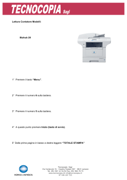
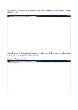
AD14.qxd
4-06-2015
12:39
Pagina 2
Libretto d’installazione
e uso
Installation and use
manual
Comando remoto Eco
Comando per raffrescatore AD14
con funzioni di regolazione base
Remote control Eco
Remote control for evaporative cooler AD14
with basic regolation functions
Revisione: A
Codice: D-LBR755
Il presente Manuale è stato redatto e stampato da Robur S.p.A.; la riproduzione anche parziale di questo
Manuale è vietata.
L'originale è archiviato presso Robur S.p.A.
Qualsiasi uso del Manuale diverso dalla consultazione personale deve essere preventivamente autorizzato
da Robur S.p.A.
Sono fatti salvi i diritti dei legittimi depositari dei marchi registrati riportati in questa pubblicazione.
Con l’obiettivo di migliorare la qualità dei suoi prodotti, Robur S.p.A. si riserva il diritto di modificare, senza
preavviso, i dati ed i contenuti del presente Manuale.
2
INDICE DEI CONTENUTI
1. FISSAGGIO A PARETE................................................................................................4
2. COLLEGAMENTI ELETTRICI.......................................................................................4
3. CARATTERISTICHE TECNICHE..................................................................................4
4. MODO DI FUNZIONAMENTO.......................................................................................4
5. FRONTALE COMANDO ...............................................................................................5
6. BLOCCO / SBLOCCO TASTIERA................................................................................5
7. ACCENSIONE SPEGNIMENTO COMANDO................................................................5
8. VISIONE / MODIFICA VELOCITA’ VENTILATORE .....................................................6
9. MODIFICA MODALITA’ FUNZIONAMENTO MACCHINA ...........................................6
10. PASSWORD PROTEZIONE PARAMETRI ...................................................................6
11. VISIONE / MODIFICA PARAMETRI STRUMENTI........................................................6
12. TABELLA PARAMETRI COMANDO ............................................................................7
13. PASSWORD ACCESSO PARAMETRI.........................................................................7
14. SEGNALAZIONI A DISPLAY........................................................................................8
15. PARAMETRI DI FABBRICA .........................................................................................8
16. SELEZIONE TIPO COMANDO: MASTER / SLAVE .....................................................8
17. SCHEMA DI COLLEGAMENTO ELETTRICO AL QUADRO DEL RAFFRESCATORE
AD 14 ............................................................................................................................9
3
PREFAZIONE
Questo libretto è rivolto a tutti coloro che devono installare e utilizzare il comado remoto ECO per
raffrescatori evaporativi serie AD 14 Robur.
In particolare il libretto è rivolto ll’installatore elettrico che lo deve collegare alla rete elettrica e all’utente
finale che deve controllarne il normale funzionamento.
Il libretto è anche rivolto agli assistenti tecnici per le principali operazioni di assistenza e manutenzione.
1.
FISSAGGIO A PARETE
2.
COLLEGAMENTI ELETTRICI
SI RACCOMANDA DI:
•
Evitare di incrociare i cavi tra loro separando le connessioni in bassissima tensione dalle connessioni
riferite ai carichi.
•
Nell’esecuzione dei collegamenti verso il modulo raffrescatore rispettare le specifiche fornite dal
costruttore.
Si ricorda che l’apparecchio non è protetto contro i sovraccarichi:
•
•
Dotare quindi le uscite delle sicurezze necessarie.
Verificare che le condizioni di impiego quali tensione di alimentazione, temperatura ambiente e umidità
rientrino nei limiti indicati.
Per il cablaggio, seguire lo schema riportato in fondo a questo documento.
3.
CARATTERISTICHE TECNICHE
Montaggio:
Protezione frontale:
Condizioni di utilizzo:
Umidità relativa ambiente:
Connessioni:
4.
a muro o su cassetta elettrica 503
IP00
Temperature ambiente –10/60°C ;
Temperatura di immagazzinamento –20/70°C
20 / 80%, senza condensa
morsetti a vite per fili con sezione max di 4mm2 e 2,5mm2
MODO DI FUNZIONAMENTO
Modificare la posizione del dip-switch della scheda elettronica a bordo del raffrescatore, in base al tipo di
comando utilizzato:
1 : in caso di utilizzo del comando EVO
ON : in caso di utilizzo del presente comando ECO
4
5.
FRONTALE COMANDO
TASTO
AZIONE / RISULTATO
Durante la fase di programmazione parametri incrementa il valore a display.
Premuto assieme al tasto DW per più di 2sec. modifica il contrasto display.
Premuto a dispositivo spento, “oFF”, seleziona l’attività del dispositivo da acceso : o sola
ventilazione o raffrescamento.
Durante la fase di programmazione parametri decrementa il valore a display.
Premuto assieme al tasto UP per più di 2sec. modifica il contrasto display.
Premuto a dispositivo spento “oFF” seleziona l’attività del dispositivo da acceso : o sola
ventilazione o raffrescamento.
Durante la fase di programmazione parametri svolge la funzione di tasto enter/conferma.
Premuto per ~1sec. consente di accendere/spegnere il dispositivo: ON/OFF.
Premuto assieme al tasto FAN per più di 2sec. consente l’accesso al menù modifica dei
parametri.
Premuto per più di 3 secondi a tastiera bloccata consente lo sblocco momentaneo della
tastiera.
Durante la fase di programmazione parametri svolge la funzione di tasto exit/uscita.
Premuto brevemente visualizza la velocità delle ventole impostata e permette l’accesso alla
fase di modifica della velocità ventilante.
Premuto assieme al tasto I/O per più di 2sec. consente l’accesso al menù modifica dei
parametri.
ICONE
Raffrescamento : icona accesa assieme alla scritta COOL , l’unità si attiva in modalità
raffrescamento.
Configurazione: Durante la fase di programmazione l’icona rimane accesa.
Ventilazione : icona accesa assieme alla scritta FAn, l’unità si attiva in modalità ventilazione.
La barra a 3 tacche indica la velocità a cui è attiva la ventilazione: una sola tacca F1 / due
tacche F2 / tre tacche F3.
6.
BLOCCO / SBLOCCO TASTIERA
Per bloccare la tastiera è sufficiente portare il parametro HL a YES (vedere paragrafi 11 e 12).
Con il blocco tastiera inserito le seguenti operazioni non sono consentite:
•
•
•
modifica/lettura dei parametri;
modifica modalità funzionamento macchina;
visione della velocità ventilante.
Quando la tastiera è bloccata ad ogni pressione sui tasti viene visualizzata la scritta “Loc”.
fino a quando la scritta “Loc”
Per sbloccare momentaneamente la tastiera mantenere premuto il tasto
cambia in “OFF”. La tastiera ritorna automaticamente nella condizione di blocco dopo 15 sec. dall’ultima
pressione di un tasto.
7.
ACCENSIONE SPEGNIMENTO COMANDO
Per accendere o spegnere il comando premere per almeno 2 secondi il tasto
quando il comando è spento il display visualizza la scritta “OFF“.
Il comando rimane alimentato anche quando è spento.
. In entrambi i casi
5
8.
VISIONE / MODIFICA VELOCITA’ VENTILATORE
Per visualizzare la velocità del ventilatore :
•
•
Premere il tasto
•
•
•
Premere il tasto
, il display ora visualizza la velocità attuale del ventilatore.
Premere il tasto
per incrementare il valore della velocità;
Premere il tasto
per decrementare il valore della velocità.
, il display ora visualizza la velocità del ventilatore.
Per uscire dalla procedura premere il tasto
Per modificare la velocità del ventilatore:
oppure attendere 8 sec. senza operare sulla tastiera.
oppure attendere 8 sec. senza
Per uscire dalla procedura e registrare le modifiche premere il tasto
operare sulla tastiera.
La velocità della ventilante può assumere tre valori: F3: velocità massima ventilatore; F2: velocità media
ventilatore; F1: velocità minima ventilatore.
9.
MODIFICA MODALITA’ FUNZIONAMENTO MACCHINA
Preme il tasto
per spegnere la macchina, scritta oFF a display. A macchina spenta premere il tasto
per modificare l’azione della macchina da accesa:
•
icona
accesa : modalità raffrescamento;
•
icona
spenta : modalità ventilazione;
o
per accendere la macchina nella modalità selezionata.
premere infine il tasto
In modalità ventilazione lo scarico è’ sempre aperto.
10. PASSWORD PROTEZIONE PARAMETRI
Il comando prevede l’inserimento di una password per avere accesso alla fase di modifica/visione di tutti i
parametri, sia per quelli di tipo “installatore” I che “costruttore” C che “utente” U. Alla richiesta di accesso ai
parametri compare la scritta “PA”. Per visionare/modificare entrambe le liste di parametri, in particolare la
per accedere al valore del
lista “installatore” / “costruttore” si agisca come segue: premere il tasto
parametro PA e inserire la password corretta servendosi dei tasti
e , al termine premere brevemente il
. Se l’operazione è stata eseguita in modo corretto il display visualizzerà il primo parametro della
tasto
tabella parametri abilitata, in caso contrario si potranno visualizzare e modificare i soli parametri appartenenti
alla lista “utente”.
In entrambi i casi, quando si scorre la lista dei parametri l’icona configurazione “
” rimane accesa.
Per accedere alla sola lista “utente”, una volta apparsa la scritta “PA” si prema 2 volte il tasto
prestare attenzione al valore del parametro PA.
senza
11. VISIONE / MODIFICA PARAMETRI STRUMENTI
Il comando prevede 3 liste di parametri: “Utente”, “Installatore” e “Costruttore”.
L’accesso/modifica alla lista dei parametri “Utente” non necessita l’inserimento di una password specifica,
invece, per i parametri di tipo “Installatore” e “Costruttore” è richiesto l’inserimento della password corretta.
Per accedere alla lista dei parametri procedere come segue:
•
•
•
•
•
6
premere i tasti
e
per almeno 2 secondi
il display visualizza la scritta “PA”
per accedere alla visione/modifica dei parametri di tipo “installatore” o “costruttore” è necessario inserire
la PAssword come descritto al punto 10 e 13;
per visualizzare/modificare i soli parametri di tipo “utente”, si prema 2 volte il tasto
premere il tasto
o
per ricercare il parametro da modificare;
;
•
•
premere il tasto
•
premere nuovamente il tasto
premere il tasto
per visualizzare il valore del parametro;
o
per modificare il valore;
per ritornare all’elenco dei parametri;
Per uscire dalla procedura e registrare le modifiche premere brevemente il tasto
senza operare sulla tastiera.
o attendere 30 sec.
12. TABELLA PARAMETRI COMANDO
Cod.
Y
Y0
Y1
Y2
Y3
Y4
Y5
Y6
Y7
Y8
Y9
YA
H
HH
HL
Parametro
Parametri regolazione raffrescamento
Ritardo avviamento raffrescamento
Periodo di raffrescamento
Tempo apertura valvola di scarico – periodo di scarico
Attesa chiusura valvola di scarico
Durata lavaggio pannelli
Periodo di risciacquo allo spegnimento
Polarità ingresso galleggiante. (NON MODIFICABILE)
0=Normalmente aperto; 1=Normalmente chiuso
Blocco ventilazione e pompa al superamento della
temperatura impostata. NO=NO; YES=SI;
Ritardo allarme riempimento vasca. 0=allarme escluso
Ritardo allarme svuotamento vasca. 0=allarme escluso
Lavaggio pannelli in ventilazione ad ogni spegnimento.
NO=NO; YES=SI;
Altri parametri
Release firmware
Blocco tastiera : 0 =NO, 1 =SI
Tipo
Range
UM
Default
C
I
C
C
C
C
C
2 - 250
2 - 500
2 - 250
2 - 250
250 - 900
2 - 250
0-1
Sec
Min
Sec
Sec
Sec
Sec
-
10
180
200
20
480
10
1
I
NO - YES
-
NO
C
C
I
0 - 999
0 - 999
NO - YES
Sec
Sec
-
0
240
NO
U
U
0 -1
-
0
ATTENZIONE : GLI ALLARMI AE SONO CORRELATI ALLA VARIAZIONE DELLO STATO DEL
GALLEGGIANTE 1.
Tramite Il parametro Y8 si imposta il ritardo segnalazione allarme riempimento vasca; se il galleggiante 1,
galleggiante di vasca piena, non modifica il proprio stato entro il tempo Y8 significa che vi è qualche
problema nel riempimento della vasca e viene quindi segnalato un evento d’allarme. Per escludere l’allarme
impostare Y8=0.
Tramite Il parametro Y9 si imposta il ritardo segnalazione allarme svuotamento vasca; se il galleggiante 1,
galleggiante di vasca piena, non modifica il proprio stato entro il tempo Y9 significa che vi è qualche
problema nello svuotamento della vasca e viene quindi segnalato un evento d’allarme. Per escludere
l’allarme impostare Y9=0.
13. PASSWORD ACCESSO PARAMETRI
Tipo
U
I
C
Descrizione
Parametri utente
Parametri Installatore
Parametri COSTRUTTORE. Questi parametri vengono tipicamente settati dal
costruttore, i valori di default possono essere diversi da quelli consigliati.
L’eventuale modifica può causare il malfunzionamento dell’apparecchiatura
collegata. Tali parametri sono visibili solo inserendo la password corretta.
PA - password
Qualsiasi
95
59
7
14. SEGNALAZIONI A DISPLAY
Display
EE
-- : -EA
Loc
oFF
En
-Etc
Etr
COOL
Fan
StOP
CLn
Significato
EEprom guasta, provare a spegnere ed accendere il comando
Posto di memoria libero
Errore galleggiante ; per annullare l’evento d’allarme togliere e ridare l’alimentazione il comando
Tastiera bloccata (non è un errore; rimuovere il blocco eventualmente)
Dispositivo spento. ATTENZIONE: la centrale rimane alimentata anche quando è spenta
Errore di comunicazione
Sensore di temperatura/umidità non collegato
Errore orologio: non è impostata l’ora. Al verificarsi di un tale evento il dispositivo imposta in
automatico l’orario alle 08:10 del lunedì. Fino a quando non verrà impostata l’ora il dispositivo
manterrà a display tale messaggio e, ad ogni power on dello stesso, imposterà nuovamente
l’orologio alle 08:10 del lunedì. Impostare l’ora corrente
Dispositivo non conforme, non è un segnale d’errore ma indica che uno degli strumenti: la
tastiera o la parte di potenza, non è quello adatto a lavorare in abbinata con l’altro. Verificare lo
stato del dip-switch 1 presente sulla scheda di bordo
Fase di raffrescamento
Fase di sola ventilazione
Programma TIMER off
Fase di lavaggio dei pannelli
15. PARAMETRI DI FABBRICA
Attenzione : questa operazione deve essere eseguita solamente da personale esperto. la modifica di tali
parametri può comportare il non corretto funzionamento dell’apparecchiatura.
Per la lista completa dei parametri speciali si veda la tabella parametri presente al paragrafo 12.
Per modificare i parametri costruttore procedere come segue:
•
Accendere alla fase di modifica di parametri come descritto al punto 11, alla richiesta della password PA
inserire, come descritto al punto 13, la cifra 59 ;
•
Se l’operazione è stata eseguita in modo corretto il display visualizzerà il primo parametro della tabella
parametri, in caso contrario si potranno visualizzare e modificare i soli parametri appartenenti alla lista
“utente”;
•
Premere il tasto
•
•
Premere il tasto
•
Premere nuovamente il tasto
Premere il tasto
o
per ricercare il parametro da modificare ;
per visualizzare il valore del parametro;
o
per modificare il valore;
per ritornare all’elenco dei parametri;
Per uscire dalla procedura e registrare le modifiche premere per almeno 2 secondi il tasto
sec. senza operare sulla tastiera.
o attendere 30
16. SELEZIONE TIPO COMANDO: MASTER / SLAVE
Attenzione : questa operazione deve essere eseguita a macchina spenta, senza alimentazione
Nel caso si vogliano collegare più moduli di potenza in parallelo allora un solo modulo deve essere il
MASTER della rete mentre i restanti moduli devono diventare dei moduli SLAVE.
Per trasformare un modulo di potenza in un modulo SLAVE si deve collegare con un ponte i morsetti V- e
M/S.
8
17. SCHEMA DI COLLEGAMENTO ELETTRICO AL QUADRO DEL
RAFFRESCATORE AD 14
9
10
INDEX
FOREWORD ....................................................................................................................13
1 – MOUNTING .................................................................................................................13
2 – ELECTRIC CONNECTIONS .......................................................................................13
3 – TECHNICAL FEATURES............................................................................................13
4 – OPERATING MODE....................................................................................................13
5 – REMOTE CONTROL DESCRIPTION .........................................................................14
6 – LOCKING / UNLOCKING THE REMOTE CONTROL UNIT .......................................14
7 – REMOTE CONTROL UNIT ON / OFF .........................................................................14
8 – FAN SPEED ................................................................................................................15
9 – REMOTE CONTROL UNIT OPERATING MODE .......................................................15
10 – PASSWORD PROTECTION PARAMETERS ...........................................................15
11 – SETTING PARAMETERS .........................................................................................15
12 – LIST OF INSTRUMENT PARAMETERS...................................................................16
13 – PASSWORD FOR PARAMETER SETTING .............................................................16
14 – DISPLAY SIGNALS ..................................................................................................16
15 – FACTORY PARAMETERS .......................................................................................17
16 – OPERATING MODE SELECTION: MASTER / SLAVE ............................................17
17 – ELECTRICAL CONNECTIONS TO ELECTRICAL PANEL OF COOLER AD 14.....18
11
EDITION: A
Code: D-LBR755
This manual has been drawn up and printed by Robur S.p.A.; whole or partial reproduction of this manual is
prohibited.
The original is filed at Robur S.p.A.
Any use of this manual other than for personal consultation must be previously authorised by Robur S.p.A.
The rights of those who have legitimately filed the registered trademarks contained within this publication are
not affected.
With the aim of continuously improving the quality of our products, Robur S.p.A. reserves the right to vary the
data and contents of this manual without prior notice.
12
FOREWORD
This manual is for anyone who must install or use the remote control for evaporative cooler AD 14.
This manual especially applies to the electrician who must connect the heating unit to the electrical system
and to the end user who must check that it functions properly.
This manual is also for the technicians regarding the principle maintenance operations.
1.
MOUNTING
ON WALL
2.
STANDARD 503 ELECTRICAL ENCLOSURE
ELECTRIC CONNECTIONS
WE RECOMMEND YOU:
•
•
To avoid crossing cables by separating very low connections from load-referred connections.
•
•
Beware to equip outputs with necessary security devices.
While establishing connections to evaporative cooling module follow carefully the specific instructions
and information provided by manufacturer.
WE REMIND YOU THAT THE INSTRUMENT IS NOT PROTECTED FROM ELECTRICAL
OVERLOADING:
3.
Make sure that employment conditions like supply tension, environment temperature and humidity are
within the indicated limits.
TECHNICAL FEATURES
Mounting:
on wall or in a standard 503 electrical enclosure
Frontal protection:
IP00
Employment conditions :
Ambient temperature: -10 / 60° C;
Storage temperature:-20 / 70° C
Relative ambient humidity:
20 / 80%, non-condensing
Connections:
screw terminals for wire with a diameter of 4mm2 and 2,5mm2
4.
OPERATING MODE
Change the position of the dip-switch of the electronic board of the cooler, depending on the type of remote
control used:
1: in case of using the remote control EVO
ON: In case of use of this remote control ECO
13
5.
REMOTE CONTROL DESCRIPTION
KEY
ACTION / RESULTS
Pressed once during modifying default parameters, increases the value.
Pressed for more than 2 seconds together with DW command, adjusts the screen contrast.
Pressed once with the unit switched OFF (the display shows “oFF”) selects the operating
mode: ventilation or cooling only.
Pressed once during modifying default parameters, decreases the value.
Pressed for more than 2 seconds together with UP command, adjusts the screen contrast.
Pressed once with the unit switched OFF (the display shows “oFF”) selects the operating
mode: ventilation or cooling only.
Pressed during programming, works like ENTER key.
Pressed for more than 1 second, switches the cooling unit ON or OFF.
Pressed for more than 2 seconds together with FAN command, changes the default
parameters.
Pressed for more than 3 seconds when the control unit is locked, temporary unlocks.
Pressed during programming, works like ESC exit key.
Pressed once selects fan speed
Pressed for more than 2 seconds together with I/O command, changes the default parameters.
SIGNAL
Cooling: when the LED is on and the label COOL is shown, the unit SCP015V153 is working in
cooling mode.
Programming: the led keeps on during programming
Ventilation: when the LED is on and the label FAn is shown, the unit SCP015V153 is working in
ventilation mode.
The 3 step progress bar shows the ventilation speed: F1 / F2 / F3.
6.
LOCKING / UNLOCKING THE REMOTE CONTROL UNIT
To lock the remote command unit, the HL parameter value must be set as YES.
WITH THE REMOTE COMMAND UNIT LOCKED, THE FOLLOWING OPERATIONS ARE NOT ALLOWED:
•
•
•
Setting the default parameters;
Setting the remote command unit operating mode;
Displaying the fan speed;
WHEN THE REMOTE CONTROL IS LOCKED, DISPLAY SHOWS “Loc” WHEN PRESSING ANY KEY.
button pressed until the display shows “OFF”.
To temporarily unlock the remote control unit, hold the
The remote control unit returns automatically to locked status after 15 sec..
7.
REMOTE CONTROL UNIT ON / OFF
Switching ON: press the
button for more than 2 seconds.
When the remote control unit is OFF, the display shows “oFF“.
The unit is always powered on, even when the display shows “off”.
14
8.
FAN SPEED
To display the fan speed:
•
•
Press
•
•
•
Press
, to display the FAN speed;
To exit press
or wait 8 sec. without pressing any key.
To change the fan speed:
, to display the current fan speed;
Press
to increase fan speed;
Press
to decrease fan speed.
or wait 8 sec.
To save changes and exit the fan setting, press
The fan speed may take on 3 values : F1 = minimum speed; F2 = average speed; F3 = max speed .
9.
REMOTE CONTROL UNIT OPERATING MODE
Press
to switch off the remote control unit.
When the display shows oFF, press or select the desired operating mode:
•
led
ON : cooling mode;
•
led
OFF : ventilation mode;
Press
to switch ON the remote control unit.
In ventilation mode, drain is always open.
10. PASSWORD PROTECTION PARAMETERS
It is possible to lock the remote control unit to avoid unauthorised tampering
When you enter the parameters lists “user” / “installer” / “factory”, the display shows “PA” and a password
may be required.
and when the display shows “PA” type the right password using key
Press the key
and
, then press
again. If the operation has been correctly performed, the first parameter of the parameter
once the key
list will be displayed, otherwise it will be possible to read and change only the parameters of the “user” list.
In both cases, the configuration icon “
when changing the parameter value.
” will light on when browsing the parameters list and blinking
To enter the “user” list only, when the display shows “PA”, just press twice the
key.
11. SETTING PARAMETERS
The device has 3 parameter lists; “user”, “installer” and “factory”. to enter/modify the “user” parameter list, it
is not necessary to insert the right password. instead the correct password is required to enter/modify the
“installer” / “factory” parameters.
To enter the parameters lists proceed as follows:
•
•
•
Press and hold
and
for 2 sec.;
The display shows “PA”:
To set the parameters belonging to the “installer” or “manufacturer” list enter the correct PAssword
following the guidelines on points 10 and 13;
•
•
To set the “user” parameters only, press twice
•
•
Press
Press
Press
or
;
to locate the parameter to alter/set;
to view the current set value;
or
to alter the set value;
• Press the
button again to go back to the parameter list;
To save changes and exit the parameter setting, press
or wait 30 sec.
15
12.
Cod.
Y
Y0
Y1
Y2
Y3
Y4
Y5
Y6
Y7
Y8
Y9
YA
H
HH
HL
LIST OF INSTRUMENT PARAMETERS
Parameter
Parameters setting cooling
Delay at cooling start up
Cooling time
Period of drain valve in open position – drain time
Delay on drain valve closing
Washing cycle of cooling pads
Washing cycle of cooling pads at power off
Polarity of float input (READ ONLY)
0=Normally open; 1=Normally closed
Fan and pump stop at temperature over the set value.
Alarm delay on sump filling. 0=alarm excluded
Alarm delay on sump empting. 0=alarm excluded
Automatic washing of cooling pads at every power off
More parameters
Release firmware (READ ONLY)
Keypad lock. 0=NO; 1=YES
Type
Range
UM
Default
C
I
C
C
C
C
C
2 … 250
2 … 500
2 … 250
2 … 250
250 … 900
2 … 250
0…1
Sec
Min
Sec
Sec
Sec
Sec
-
10
180
200
20
480
10
1
I
C
C
I
NO … YES
0 … 999
0 … 999
NO … YES
Sec
Sec
-
NO
0
240
NO
U
U
0…1
-
0
WARNING: ALARMS AE ARE RELATED TO THE VARIATION OF THE FLOAT –1 STATUS
Parameter Y8 sets the delay in signalling the alarm of full tank; should float 1 (full tank float) not change its
status within a time Y8, it means that there is a problem with the tank fill and the controller signal an alarm.
To exclude the alarm set Y8 = 0.
Parameter Y9 sets the delay in signalling the alarm of empty tank; should float 1 (full tank float) not change
its status within a time Y9, it means that there is a problem with the tank fill and the controller signal an
alarm. To exclude the alarm set Y9 = 0.
13.
PASSWORD FOR PARAMETER SETTING
Type
U
I
Description
USER parameters
INSTALLER parameters. Carefully read all instructions in this manual, before
changing any parameters.
FACTORY parameters. These parameters are usually factory preset; the default
values may differ from the suggested ones. Changing these parameters may
cause a bad functioning of the device. These parameters are visible only by
entering the right password.
C
14.
Display
EE
-- : -EA
Loc
oFF
En
-Etc
Etr
COOL
Fan
StOP
CLn
16
PA - password
any
95
59
DISPLAY SIGNALS
Meaning
Eeprom failure, turn the unit off and on again;
Free space in memory;
Generic error turn off the device and start it again;
It is not an error. Control unit locked.
Unit off. ATTENTION: the unit is always powered-on even when it is turned off.
Communication error
Humidity/Temperature sensor not connected.
Clock error. The time on the remote controller is not set. When this event occurs the device
automatically sets the timer to Monday 8:10am. The device will keep displaying “Etc” and set
automatically the timer to Monday 8:10am at every power on. Set the current time.
Device not in conformity, it is an error signal but indicates that one of the instruments: the
keyboard or the power part, is not suited to work in combination with each other. Check the
status of the dip-switch 1 on the card board
Cooling cycle
Vent only cycle;
Timer program OFF;
Pads wash cycle;
15.
FACTORY PARAMETERS
WARNING! This operation must be executed by expert personnel. the change of these parameters can
cause the not right operation of the device.
See paragraph n.°12 for the complete SPECIAL parameter list. Here following the explanation of some of
these parameters
To change the FACTORY parameters proceed as follows:
•
Follows the guidelines on point 11 to enter the parameter editing procedure; when the display shows the
label PA enter the password 59 as described on point 13;
•
If the operation has been correctly performed, the first parameter of the parameter list will be displayed,
otherwise it will be possible to read and change only the parameters of the “user” list.
•
•
Press
•
•
Press
•
Press the
Press
or
to locate the parameter to alter ;
to view the current set value;
or
to alter the set value;
button again to go back to the parameter list;
To save changes and exit the setting, press and hold
16.
for 2 seconds or or wait 30sec.
OPERATING MODE SELECTION: MASTER / SLAVE
NOTE: make sure the evaporative cooler is switched off and without power supply before performing this
operation.
In case of more power modules connected in parallel, just one of them will be the MASTER of the network,
while the others will be the SLAVE modules.
In order to change a power module into a SLAVE module, make a bridge between V- and M/S.
17
17.
18
ELECTRICAL CONNECTIONS TO ELECTRICAL PANEL OF
COOLER AD 14
Codice: D-LBR755 rev.A 15 MEDSVI 055 09/06/2015
Robur is dedicated to dynamic progression
in research, development and promotion
of safe, environmentally-friendly, energy-efficiency products,
through the commitment and caring
of its employees and partners.
Robur Mission
Robur Spa
advanced heating
and cooling technologies
Via Parigi 4/6
24040 Verdellino/Zingonia (Bg) Italy
T +39 035 888111 F +39 035 4821334
www.robur.com
[email protected]
Scarica