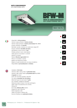
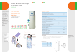
AD14.qxd
4-06-2015
12:10
Pagina 1
Libretto d’installazione
uso e manutenzione
Installation, use and
maintenance manual
Raffrescatore evaporativo AD 14
Per raffrescare in modo naturale, semplice e economico
edifici di media e grande dimensione.
Evaporative cooler AD 14
Cool, natural, simple air distribution system
designed for the cooling of industrial
and commercial buildings
Revisione: A
Codice: D-LBR754
Il presente Manuale è stato redatto e stampato da Robur S.p.A.; la riproduzione anche parziale di questo
Manuale è vietata.
L'originale è archiviato presso Robur S.p.A.
Qualsiasi uso del Manuale diverso dalla consultazione personale deve essere preventivamente autorizzato
da Robur S.p.A.
Sono fatti salvi i diritti dei legittimi depositari dei marchi registrati riportati in questa pubblicazione.
Con l’obiettivo di migliorare la qualità dei suoi prodotti, Robur S.p.A. si riserva il diritto di modificare, senza
preavviso, i dati ed i contenuti del presente Manuale.
2
INDICE DEI CONTENUTI
1. CARATTERISTICHE .....................................................................................................4
1.1
1.2
1.3
1.4
Presentazione del Raffrescatore Evaporativo AD 14 ........................................................ 4
Uso previsto ...................................................................................................................... 4
Dati identificativi del raffrescatore ..................................................................................... 4
Quadro elettrico................................................................................................................. 5
2. TRASPORTO, MOVIMENTAZIONE, DISIMBALLAGGIO, IMMAGAZZINAMENTO ....5
2.1
2.2
2.3
2.4
Ricevimento materiale....................................................................................................... 5
Trasporto, movimentazione e sollevamento...................................................................... 5
Disimballaggio ................................................................................................................... 6
Immagazzinamento ........................................................................................................... 6
3. POSIZIONAMENTO E INSTALLAZIONE .....................................................................6
3.1
3.2
3.3
3.4
3.5
3.6
Avvertenze generali........................................................................................................... 6
Installazione a tetto ........................................................................................................... 6
Installazione a parete/finestra ........................................................................................... 9
Note a completamento .................................................................................................... 10
Allacciamento alla rete elettrica....................................................................................... 10
Allacciamento alla rete idrica........................................................................................... 10
4. SISTEMI DI PROTEZIONE..........................................................................................11
4.1
4.2
4.3
4.4
4.5
Dispositivi di protezione................................................................................................... 11
Segnaletica applicata a bordo macchina......................................................................... 11
Abbigliamento.................................................................................................................. 11
Rischi residui ................................................................................................................... 12
Situazioni d’emergenza ................................................................................................... 12
5. NOTE SUL FUNZIONAMENTO ..................................................................................12
6. USO DEL RAFFRESCATORE EVAPORATIVO .........................................................13
6.1
6.2
Prima messa in funzione ................................................................................................. 13
Comando remoto per la regolazione del funzionamento del raffrescatore...................... 13
7. MANUTENZIONE ........................................................................................................13
7.1
7.2
7.3
Manutenzione a fine stagione ......................................................................................... 13
Manutenzione pre-stagionale .......................................................................................... 13
Sicurezza per la manutenzione ....................................................................................... 14
8. SMANTELLAMENTO..................................................................................................15
DISEGNI DIMENSIONALI .................................................................................................30
SCHEMI DI COLLEGAMENTO ELETTRICO....................................................................31
CARATTERISTICHE TECNICHE......................................................................................32
3
PREFAZIONE
Questo libretto è rivolto a tutti coloro che devono installare e utilizzare i raffrescatori evaporativi serie AD 14
Robur.
In particolare il libretto è rivolto all’installatore idraulico che deve installare il raffrescatore, all’installatore
elettrico che lo deve collegare alla rete elettrica e all’utente finale che deve controllarne il normale
funzionamento.
Il libretto è anche rivolto agli assistenti tecnici per le principali operazioni di assistenza e manutenzione.
1.
CARATTERISTICHE
1.1 PRESENTAZIONE DEL RAFFRESCATORE EVAPORATIVO AD 14
Per migliorare il microclima estivo all’interno di un locale produttivo, commerciale o altro occorre ventilare
l’ambiente con molti ricambi d’aria nuova e filtrata, possibilmente raffreddata. Nel caso di grandi locali, ad
esempio quelli industriali, un impianto di condizionamento spesso non è consigliabile in quanto, a causa del
grande volume d’aria da raffreddare e dei carichi termici di processo da neutralizzare, la quantità di energia
necessaria è elevatissima e l’effetto di raffreddamento viene ridotto dagli impianti di estrazione dell’aria
esausta e dalla frequente apertura dei portoni per lo svolgimento dell’attività.
Un’ottima soluzione è rappresentata da un impianto di raffrescatori evaporativi che raffreddano l'aria con un
principio naturale: l'aria passa attraverso speciali filtri bagnati d'acqua, cede parte del suo calore durante il
processo di evaporazione dell'acqua ed abbassa la sua temperatura. L'assenza di macchine frigorifere
riduce al minimo i consumi di energia e consente di trattare grandi volumi d'aria per i molti ricambi necessari.
1.2 USO PREVISTO
Il raffrescatore evaporativo AD 14 può essere installato in tutti gli ambienti dove è necessario un
miglioramento del microclima, dove occorre ventilare l'ambiente con molti ricambi d'aria nuova e filtrata,
possibilmente raffrescata, come :
•
•
•
locali produttivi e artigianali
locali commerciali e magazzini
locali sportivi in genere
E’ assolutamente vietato modificare la macchina e la sua destinazione d’uso.
Il PRODUTTORE declina ogni responsabilità per eventuali danni che potrebbero,
direttamente o indirettamente, derivare da persone esposte o cose, in conseguenza di uso
improprio da quello per cui è stata concepita la macchina, installazione non corretta,
alimentazioni non appropriate, ambienti di installazione modificati o diversi da quelli
comunicati in fase di conferma d’ordine, gravi carenze nella manutenzione, interventi e
modifiche non autorizzati, utilizzo di ricambi non originali, rimozione delle protezioni attive e
passive, inosservanza delle istruzioni per l’uso, negligenza, ecc.
1.3 DATI IDENTIFICATIVI DEL RAFFRESCATORE
I dati identificativi della macchina sono riportati sulla scheda di garanzia fornita al cliente in allegato al resto
della documentazione e sulla targhetta identificativa presente sulla macchina stessa.
In caso di richiesta di Assistenza Tecnica o di parti di ricambio, citare sempre il modello ed il numero di
matricola della macchina.
NON è consentito per nessuna ragione utilizzare la macchina per scopi differenti da quelli per cui è stata
progettata, né utilizzarla con modalità differenti da quelle riportate nel presente manuale.
NON installare la macchina in locali chiusi, l’installazione della stessa dovrà avvenire all’esterno dei locali da
trattare, salvo esplicita approvazione del costruttore .
NON mettere in funzione la macchina se non e’ collegata al relativo impianto (canale) di distribuzione aria.
Durante il funzionamento dell’impianto non toccare il ventilatore - Pericolo meccanico.
E’ vietato operare su parti in movimento.
E’ assolutamente vietato installare i raffrescatori evaporativi in ambienti con pericolo
d’esplosione. 4
1.4 QUADRO ELETTRICO
Il quadro elettrico fornito è conforme alla norma EN 60204/1.
E 'assolutamente vietato apportare modifiche al quadro elettrico.
2.
TRASPORTO, MOVIMENTAZIONE, DISIMBALLAGGIO,
IMMAGAZZINAMENTO
2.1 RICEVIMENTO MATERIALE
Alla consegna della fornitura presso il cliente è indispensabile verificare lo stato di integrità della merce.
)
Prestare attenzione nel maneggiare i Raffrescatori Evaporativi durante le fasi di scarico dal
mezzo di trasporto, la movimentazione ed il posizionamento, per evitare danni
all’apparecchio. Evitare il contatto con elementi che potrebbero danneggiare l’apparecchio.
Robur SpA declina ogni responsabilità per danneggiamenti arrecati ai Raffrescatori
Evaporativi dovuti a trasporto, carico e scarico mal eseguiti o a mancanza di protezione dagli
agenti atmosferici.
Verificare gli imballi ed il loro contenuto, nel caso si riscontrassero danni dovuti al trasporto,
apporre riserva di danno sul documento di spedizione controfirmato dal vettore e
successivamente inviarne una copia alla Robur SpA.
2.2 TRASPORTO, MOVIMENTAZIONE E SOLLEVAMENTO
Allargare le forche in modo da equilibrare il carico.
2.2.1
Sollevamento con funi
E’ vivamente consigliato applicare le funi come indicato in figura, interponendo distanziali di lunghezza
adeguata per impedire che le funi stringendosi non danneggino l’involucro.
Lo smaltimento dei materiali di imballaggio deve avvenire in conformità alle normative vigenti nel
Paese di destinazione dei Raffrescatori Evaporativi.
Liberare dall’imballo tutti i componenti avvolti o racchiusi nello stesso e raccoglierli in modo da prevenire
potenziali pericoli di incendio e soffocamento di persone o animali.
Lasciare l’apparecchio appoggiato sul proprio imballo di trasporto con le eventuali protezioni in modo che la
parte inferiore rimanga sollevata e non venga danneggiata sino a quando verrà installata sui dispositivi
previsti.
Per la movimentazione utilizzare, in funzione del peso, mezzi adeguati come previsto dalla direttiva
89/391/CEE e successive modifiche, facendo effettuare il sollevamento solo da personale qualificato.
E’ ASSOLUTAMENTE VIETATO sostare sotto i carichi sospesi ed all’interno del raggio di azione del
mezzo di sollevamento.
5
2.3 DISIMBALLAGGIO
Appoggiare con prudenza la merce in modo da evitarne bruschi spostamenti o, peggio, cadute.
2.4 IMMAGAZZINAMENTO
)
Durante il trasporto e l’immagazzinamento assicurarsi che la temperatura ambiente sia
compresa tra -10 e 50 °C.
Qualora i raffrescatori evaporativi AD 14 debbano essere immagazzinati, assicurarsi che l'umidità relativa del
magazzino sia compresa tra il 5% ed il 90%.
3.
POSIZIONAMENTO E INSTALLAZIONE
3.1 AVVERTENZE GENERALI
Prima di procedere all’installazione assicurarsi che ogni raffrescatore evaporativo sia stato disimballato e ne
sia stata verificata l’integrità.
La messa in opera e l’installazione dei raffrescatori evaporativi sono operazioni che possono compromettere
il buon funzionamento dell’impianto o, peggio, causare danni irreversibili alla macchina. Queste operazioni
dovranno essere eseguite da personale abilitato ed in osservanza delle Leggi vigenti nel Paese di
destinazione degli stessi.
3.2 INSTALLAZIONE A TETTO
Predisporre e fissare un canale flangiato di ingresso aria avente le medesime dimensioni flangia del tronco di
canale della macchina (600 x 600 mm). La macchina è provvista di un tronco di canale flangiato che andrà
fissato sulla flangia del canale precedentemente predisposto.
Portare la base del raffrescatore evaporativo sul punto di fissaggio.
Procedere al fissaggio delle due flange (base-canale) mediante bullonatura.
Si consiglia di interporre della pasta siliconica tra i fissaggi delle flange per garantirne il perfetto isolamento
dagli agenti esterni.
6
Posizionare e fissare i montanti alla base del raffrescatore utilizzando le viti in dotazione.
Verificare il serraggio della fascetta stringi tubo sul tubo flessibile collegato alla pompa.
Applicare i pannelli umidificanti appoggiandoli ai montanti mantenendo la gola, ricavata su un lato del
pannello, verso l’alto e verso la parte esterna della macchina.
7
Inserire nella gola dei pannelli le piattine di distribuzione acqua. Verificare che queste siano ben premute fino
a battuta inferiore della loro sede.
Inserire il distributore d’acqua nelle gole dei pannelli umidificanti facendo attenzione che i supporti dello
stesso appoggino in maniera uniforme sulle piattine di distribuzione.
Mantenere il portagomma in corrispondenza del lato della macchina dove è presente la pompa dell’acqua,
avendo cura di praticare, in corrispondenza del portagomma stesso, una apertura nel pannello umidificante
per permetterne il passaggio.
Collegare al porta gomma del distributore il tubo flessibile proveniente dalla pompa e fissarlo mediante
fascetta stringitubo.
Inserire le griglie ai lati e al posteriore della macchina, fissandole con i fermagli forniti in dotazione. Non
montare la griglia sul lato anteriore (lato componenti/ collegamenti).
Inserire i fermagli sui due lati della griglia, inizialmente fino al “primo scatto” e successivamente forzare fino
al loro completo inserimento in modo tale che non sporgano, in altezza, oltre i pannelli umidificanti.
8
Posizionare il cappello senza fissarlo per permettere il successivo inserimento della griglia frontale.
Si dovrà sollevare il cappello fino a che la griglia occupi correttamente la propria sede.
Non fissare la griglia frontale con i fermagli perché ciò impedirebbe un agevole accesso all’interno della
macchina per eventuali operazioni di manutenzione.
Dopo avere posizionato la griglia frontale, fissare il cappello mediante le viti in dotazione.
3.3 INSTALLAZIONE A PARETE/FINESTRA
Predisporre e fissare un telaio per il sostegno della macchina ed un canale flangiato di ingresso aria avente
le medesime dimensioni flangia del tronco di canale della macchina.
La macchina è provvista di un tronco di canale flangiato che andrà fissato sulla flangia del canale
precedentemente predisposto.
Verificare che il telaio di sostegno sia in grado di sopportare il peso della macchina e tale da non causare
vibrazioni e che sia perfettamente in piano (posizionare in bolla).
Portare il raffrescatore evaporativo sul punto di fissaggio.
Procedere al fissaggio delle due flange (base-canale) e della base al telaio mediante bullonatura.
Si consiglia di interporre della pasta siliconica tra i fissaggi delle flange per garantirne il perfetto isolamento
dagli agenti esterni.
9
3.4 NOTE A COMPLETAMENTO
Predisporre all’interno dell’edificio i punti d’ancoraggio per le catene di sostegno della condotta d’immissione
aria. Questi dovranno essere definiti in modo tale che le catene non provochino eccessivi sforzi sulla
condotta stessa. Accertarsi che questa sia in asse con la macchina.
Per l’ancoraggio al soffitto o a parete dei canali utilizzare catene e relativi accessori muniti di certificato di
collaudo, realizzati in acciaio zincato o inox, aventi il diametro del filo non inferiore a 3mm o comunque
dimensionato in relazione al peso che dovrà sostenere, tenendo conto dei margini di sicurezza imposti dalle
normative.
Non utilizzare componenti in leghe d’alluminio o similari.
I canali devono essere dimensionati in funzione dell’impianto e delle caratteristiche aerauliche del
ventilatore. Un errato calcolo delle canalizzazioni causa perdite o eccessi di potenza provocando
possibili anomalie di funzionamento.
Al termine dell’installazione dell’impianto, ruotare verso l’esterno le alette dei diffusori e regolarle in modo
ottimale per direzionare il flusso d’aria.
3.5 ALLACCIAMENTO ALLA RETE ELETTRICA
Ogni apparecchio deve essere collegato alle rete di alimentazione elettrica attraverso un sezionatore
onnipolare avente una distanza minima fra i contatti di almeno 3 mm e un interruttore magnetotermico
salvamotore predisponendoli in una posizione facilmente raggiungibile dall’utente.
L’impianto elettrico deve essere realizzato in conformità alle norme vigenti del paese in cui la
macchina verrà installata.
L’allacciamento alla rete elettrica deve essere obbligatoriamente eseguito da personale abilitato.
Tutta la componentistica utilizzata per l’ allacciamento elettrico deve essere di tipo certificato. Prima
di iniziare qualsiasi operazione assicurarsi che la linea di alimentazione generale sia sezionata.
Prevedere un efficace collegamento di messa a terra.
Il raffrescatore è fornito di un quadro elettrico di collegamento, applicato alla base-canale, contenente un
sezionatore per il collegamento alla linea di alimentazione elettrica e una morsettiera per il collegamento dei
cavi del modulo di comando remoto e di un modulo di comando remoto dell’apparecchio da posizionarsi
all’interno dell’ambiente.
Per il collegamento alla linea di alimentazione elettrica, utilizzare un cavo multipolare + terra di tipo
previsto dalle normative vigenti.
Per il collegamento del comando remoto, utilizzare un cavo schermato del tipo 20 AWG - 5 poli con
sezione min. 0,50 mm2 – Sviluppo massimo : 25 metri.
Eseguire i collegamenti seguendo lo schema di riferimento che potrete trovare in fondo a questo
manuale o all’interno del quadro di comando.
E’ assolutamente necessario rispettare la polarità delle fasi e/o la numerazione dei cavi/morsetti.
3.6 ALLACCIAMENTO ALLA RETE IDRICA
Il raffrescatore AD 14 è dotato, per l'alimentazione dell'acqua, di un attacco da 3/8" presente nella parte
inferiore al quale si consiglia di prevedere un collegamento con un rubinetto di intercettazione ed un sistema
che permetta lo svuotamento dell'impianto prima della stagione invernale.
Inserire un filtro antisabbia sull’impianto di alimentazione idrica della macchina.
E’ necessario realizzare una condotta in grado di garantire una portata minima di 5 ÷10 l/minuto ad una
pressione di 1.5 ÷ 3 bar ( pressione massima consentita: 6 bar ).
Si consiglia di realizzare la condotta dell’acqua all’interno del fabbricato, in caso contrario prevedere una
tubazione adeguatamente isolata.
Si raccomanda l’utilizzo di acqua potabile, di durezza non superiore ai 27°f e non inferiore ai 7°f.
In caso di durezza superiore, dotare l’impianto di un sistema di addolcimento.
Non utilizzare acqua demineralizzata.
10
Procedere al collegamento del manicotto da 3/8” alla rete idrica principale senza sollecitarlo eccessivamente.
La macchina è inoltre dotata di un manicotto filettato Ø 60 mm per lo scarico dell’acqua .
Collegare al manicotto la tubazione flessibile, in dotazione, fissandola mediante fascetta stringi tubo
ponendo attenzione a non sollecitare il manicotto stesso ed evitando assolutamente che questo possa
ruotare.
Se dovesse essere presente un sistema di scarico centralizzato, convogliare il tubo al sistema di scarico
centralizzato secondo le norme igieniche vigenti nel paese in cui la macchina verrà installata.
4.
SISTEMI DI PROTEZIONE
4.1 DISPOSITIVI DI PROTEZIONE
Per ottemperare alle disposizioni contenute nelle Direttive Comunitarie applicabili all’unità alla quale è riferito
il presente manuale d’uso e manutenzione, il costruttore ha predisposto sull’unità stessa i sistemi di
sicurezza previsti dalla legislazione vigente.
4.2 SEGNALETICA APPLICATA A BORDO MACCHINA
ORGANI ELETTRICI SOTTO TENSIONE segnala il pericolo dovuto a parti elettriche sotto tensione
ORGANI MECCANICI
segnala il pericolo dovuto a parti meccaniche in movimento
4.3 ABBIGLIAMENTO
Essendo l’apparecchio destinato ad installazioni in posizioni non direttamente raggiungibili dagli utenti
durante il normale utilizzo, non sono applicabili particolari prescrizioni per l’abbigliamento del personale.
11
4.4 RISCHI RESIDUI
Vietato utilizzare acqua per pulire componenti elettromeccanici.
Pericolo di elettrocuzione.
Prestare attenzione al movimento del ventilatore. Non introdurre gli arti. Pericolo meccanico. 4.5 SITUAZIONI D’EMERGENZA
In caso di emergenza fermare immediatamente l’apparecchio e aprire il circuito elettrico
tramite il sezionatore onnipolare, identificare ed eliminare il problema controllandone le cause
di origine, contattare il servizio di assistenza tecnica.
E’ assolutamente vietato utilizzare acqua per spegnere incendi.
Utilizzare esclusivamente estintori a polvere o ad anidride carbonica.
5.
NOTE SUL FUNZIONAMENTO
Un raffrescatore evaporativo funziona sulla base di un semplice principio: introdurre nel locale grandi
quantità di aria fresca e rimuovere l’aria calda viziata attraverso porte, finestre o altre aperture
d’evacuazione. ARIA FRESCA IN ENTRATA = ARIA CALDA IN USCITA. Se è possibile espellere tutta l’aria
introdotta, il sistema funzionerà alla sua massima efficacia. Se l’insieme delle aperture non è in grado di
espellere il grande volume d’aria introdotto l’efficacia del sistema verrà compromessa. La condizione ideale,
è quella di posizionare i diffusori d’aria lontano dalle aperture (finestre, portoni, ecc.) del locale. Aprendo una
finestra lontano dai diffusori, l’aria attraverserà il locale raffrescandolo. Regolando le dimensioni di apertura
di finestre e porte, può essere raggiunta la massima efficacia. Non chiudere mai le aperture; chiudendole
verranno preclusi i ricambi d’aria con il conseguente rischio di ridurre l’effetto raffrescante e di aumentare il
tasso di umidità relativa all’interno del locale stesso.
Per ottimizzare il rendimento, bisognerebbe garantire circa 0,5 mq di estrazione per ogni 1.000 m3 d’aria
trattati (fare riferimento ai dati di progetto).
E’ regola di tutti i raffrescatori evaporativi, che più “secca” è l’aria esterna di ricambio, più grande è la
differenza di temperatura o capacità di raffrescamento che potrà essere raggiunta. Il Vostro raffrescatore
d’aria non funzionerà al massimo dell’efficienza nei giorni molto umidi, ma raggiungerà ugualmente un livello
di raffrescamento efficace.
In aree con umidità elevata il raffrescatore d’aria dovrà essere sovradimensionato per garantire un maggiore
ricambio d’aria o, in altre parole, con una capacità più elevata per compensare la poca differenza di
temperatura. In queste aree, il massimo raffrescamento verrà raggiunto assicurandosi che ci siano più punti
d’evacuazione d’aria di quelli sufficienti e che l’unità venga messa in funzione di mattino presto per bloccare
l’aumento del calore latente all’interno dello spazio raffrescato. Il vostro fornitore progetterà il vostro sistema
in funzione delle condizioni climatiche locali. Nei giorni in cui il tasso d’umidità relativa esterna sarà prossima
e superiore al 70%-75%, consigliamo di far funzionare l’unità solo in modalità di ventilazione.
L’efficienza di raffrescamento di un sistema non è relativa solo all’efficienza dell’unità impiegata, ma anche
alla progettazione della canalizzazione e all’installazione. Soffitti isolati diminuiranno la temperatura interna
significativamente rispetto a soffitti non isolati. Lo stesso concetto è applicabile per la canalizzazione
dell’aria.
Durante il normale funzionamento del sistema in modalità di raffrescamento, il processo di evaporazione
produce un accumulo di sali minerali e residui solidi nell’acqua di scarico; quest’acqua NON E’ POTABILE.
12
6.
USO DEL RAFFRESCATORE EVAPORATIVO
6.1 PRIMA MESSA IN FUNZIONE
Per un corretto ed ottimale funzionamento ed utilizzo dell’impianto/macchina è indispensabile che, all’atto
della prima “messa in moto” (in modalità di raffrescamento), il ventilatore venga posto alla velocità minima e
che questa venga mantenuta per almeno un giorno.
La mancata esecuzione della suddetta procedura potrebbe causare, solo per il primo giorno di utilizzo, un
mal funzionamento dei pannelli evaporanti con conseguente fuori uscita di gocce d’acqua dalle
canalizzazioni.
Durante la prima messa in funzione del Vs. sistema di raffrescamento, potrebbe essere avvertito dell’odore
inconsueto: quando i pannelli evaporanti inizieranno a bagnarsi potrebbero emettere un odore particolare
per qualche ora, tale odore è caratteristico dei materiali in cellulosa trattata ma non è nocivo.
Anche il motore del ventilatore potrebbe avere un odore “caratteristico” per un breve periodo, causato dal
riscaldamento iniziale e dai residui di oli o vernici sulla superficie del motore stesso.
6.2 COMANDO REMOTO PER LA REGOLAZIONE DEL FUNZIONAMENTO DEL
RAFFRESCATORE
Le unità di raffrescamento sono corredate di un modulo di comando remoto che ne permette le varie
operazioni di gestione. Per il dettaglio circa le modalità di funzionamento, riferirsi al Libretto di
Istruzione relativo al Comando remoto.
7.
MANUTENZIONE
Raccomandiamo un’assistenza annuale al sistema per mantenerlo in condizioni di funzionamento perfette.
Prima dell’inizio del periodo di utilizzo è necessario verificare il buon funzionamento dell’apparecchio al fine
di provvedere in tempo utile alle eventuali manutenzioni/riparazioni.
7.1 MANUTENZIONE A FINE STAGIONE
•
•
•
•
•
Togliere tensione all’unità, tramite l’interruttore di alimentazione generale a muro.
Chiudere l’alimentazione dell’acqua.
Svuotare l’impianto di alimentazione acqua per evitare rotture dovute al gelo.
Rimuovere il coperchio della macchina.
Controllare che i canali dell’acqua siano puliti e che non ci siano ostruzioni nel distributore d’acqua, nella
parte superiore dell’unità. Rimuovere eventuali detriti dal pescante della pompa di ricircolo acqua.
•
Delicatamente ma accuratamente, pulire la base dell’unità. Usare un detergente delicato, ma non
solvente in quanto potrebbe reagire con il materiale plastico.
•
•
Rimettere il coperchio e assicurarsi che sia ben fissato tramite gli appositi bulloni.
Applicare alla macchina la copertura di protezione (optional) verificando preventivamente che questa
non sia danneggiata e, nel caso lo fosse, verificare che questa sia riparabile altrimenti procedere alla
sua sostituzione.
Per evitare che la macchina possa subire danni a causa dei fattori climatici ai quali potrebbe essere
sottoposta durante la messa a riposo (smog, piogge acide, gelo, ecc.) è’ opportuno che la copertura
di protezione sia stata applicata a fine stagione.
7.2 MANUTENZIONE PRE-STAGIONALE
•
•
•
•
Togliere tensione all’unità, tramite il sezionatore di rete a bordo macchina.
Rimuovere la copertura di protezione verificando che questa non abbia subito danni, pulirla
accuratamente con detergente delicato e riporla in un luogo che non sia esposta direttamente alle
intemperie.
Rimuovere il coperchio della macchina.
Se necessario, pulire la base.
13
•
Controllare i pannelli evaporanti ed eventualmente pulirli da eventuali depositi limacciosi mediante
lavaggio con acqua e da depositi calcarei di piccola entità mediante scuotimento. In presenza di
incrostazioni rilevanti è necessario sostituire il pannello.
•
Controllare che i canali dell’acqua siano puliti e che non ci siano ostruzioni nel distributore d’acqua, nella
parte superiore dell’unità. Rimuovere eventuali detriti dal pescante della pompa di ricircolo acqua.
•
•
Alimentare elettricamente la macchina tramite il sezionatore di rete a bordo macchina.
•
•
•
•
•
Aprire l’alimentazione dell’acqua. Far funzionare il sistema in modalità di RAFFRESCAMENTO ed
osservare che la valvola di scarico si chiuda ed il serbatoio si riempia di acqua fino al punto in cui la
valvola di carico cesserà d’immettere acqua.
Verificare che l’acqua si distribuisca uniformemente su tutti i pannelli evaporanti.
Verificare il funzionamento della valvola di scarico, assicurarsi che si apra entro 5 minuti dopo aver
spento la macchina.
Verificare eventuali perdite d’acqua dalle vasche e dalle tubazioni di alimentazione.
Controllare lo stato di conservazione dei cavi elettrici.
Rimettere a posto il coperchio e assicurarsi che sia ben fissato.
)
Il costruttore non si assume alcuna responsabilità o impegno di garanzia per danni causati da
inosservanza delle prescrizioni e da un uso improprio dell’apparecchio da parte dell’Utente.
7.3 SICUREZZA PER LA MANUTENZIONE
7.3.1
Abbigliamento
Il personale preposto alla manutenzione della macchina non deve indossare indumenti con maniche larghe,
lacci o cinture che possono essere causa di pericolo; inoltre deve utilizzare i dispositivi di protezione
individuale in conformità alle disposizioni legislative vigenti.
Il personale addetto alla manutenzione deve essere qualificato professionalmente.
Prima di svolgere qualsiasi operazione di manutenzione leggere attentamente questa sezione del
manuale d’uso. Per qualsiasi necessità contattare il servizio di assistenza tecnica. Il costruttore non
risponde di eventuali danni o disfunzioni se occorsi per il mancato rispetto delle indicazioni
contenute nella presente sezione del manuale d’uso.
Durante la manutenzione esporre in reparto la segnaletica “Lavori in corso” in modo visibile da tutte le zone
di accesso. Riportare tutti gli interventi di manutenzione eseguiti su un apposito registro, avendo cura di
registrare: data, ora, tipo di intervento e nominativo dell’esecutore. L’utilizzo di eventuali solventi per pulizia
dovrà essere eseguito in modo da evitare che gli stessi deteriorino i cavi elettrici.
Il personale addetto alla manutenzione che utilizzi solventi deve essere dotato dei dispositivi di
protezione individuale (occhiali di sicurezza, maschera filtro, guanti di tipo idoneo al contatto col
solvente utilizzato. Durante l’uso di solventi è severamente vietato fumare ed utilizzare fiamme libere.
Al termine areare il locale per favorire lo smaltimento dei vapori residui.
E’ VIETATO:
•
•
•
•
•
•
•
14
Depositare materiale combustibile nelle vicinanze dei quadri elettrici.
Interventire sugli apparati elettrici senza aver preventivamente sezionato la linea di alimentazione
elettrica.
Intervenire su qualsiasi parte dell’unità prima di aver fermato l’impianto.
Operare con i sistemi di sicurezza disattivati o rimossi.
Disattivare o eludere le segnalazioni di allarme.
Ignorare le avvertenze e la segnaletica applicate a bordo macchina.
Far funzionare l’unità con le protezioni metalliche rimosse.
8.
SMANTELLAMENTO
In caso di smontaggio o alienazione dell’impianto occorre recuperare tutti i materiali che lo costituiscono ed
avviarli agli appositi centri di raccolta e smaltimento rivolgendosi preferibilmente ad aziende specializzate del
settore.
Lo smontaggio dell’impianto deve essere effettuato da personale specializzato dotato di attrezzature
idonee e di mezzi personali di protezione individuale.
Non fumare e non utilizzare fiamme libere durante lo smantellamento.
15
16
INDEX
FOREWORD ....................................................................................................................19
SECTION 1 – CHARACTERISTICS..................................................................................19
1.1 Presentation of the ColdAir Evaporative Cooler .................................................................... 19
1.2 Foreseen use......................................................................................................................... 19
1.3 Machine identification data .................................................................................................... 19
1.4 Electrical boards .................................................................................................................... 20
SECTION 2 – TRANSPORTATION, HANDLING, UNPACKING, STORAGE ..................20
2.1 Delivery of the unit ................................................................................................................. 20
2.2 Transportation, handling and lifting........................................................................................ 20
2.2.1 Lifting with cables ............................................................................................................... 20
2.3 Unpacking the equipment ...................................................................................................... 21
2.4 Storage .................................................................................................................................. 21
SECTION 3 – POSITIONING and INSTALLATION ..........................................................21
3.1 General warnings .................................................................................................................. 21
3.2 Roof installation ..................................................................................................................... 21
3.3 Wall/window installation ...................................................................................................... 24
3.4 Notes ..................................................................................................................................... 25
3.5 Connection to the power supply ............................................................................................ 25
3.6 Connection to the water supply ............................................................................................. 25
SECTION 4 – PROTECTION DEVICES............................................................................26
4.1 Protection devices ................................................................................................................. 26
4.2 Caution signs applied on the unit........................................................................................... 26
4.3 Clothing.................................................................................................................................. 26
4.4 Residual risks ........................................................................................................................ 27
4.5 Emergency situations ............................................................................................................ 27
SECTION 5 – functioning notes......................................................................................27
SECTION 6 – USING THE EVAPORATIVE COOLING UNIT ..........................................28
6.1 First start up ......................................................................................................................... 28
6.2 Remote Control (display) ..................................................................................................... 28
SECTION 7 – MAINTENANCE ........................................................................................28
7.1 End of season maintenance .................................................................................................. 28
7.2 Pre season maintenance ....................................................................................................... 28
7.3 Maintenance safety regulations ............................................................................................ 29
7.3.1 Abbigliamento .................................................................................................................... 29
SECTION 8 – DISMALTING .............................................................................................29
TECHNICAL DRAWINGS & FEATURES .............................................................30, 31, 32
17
EDITION: A
Code: D-LBR754
This manual has been drawn up and printed by Robur S.p.A.; whole or partial reproduction of this manual is
prohibited.
The original is filed at Robur S.p.A.
Any use of this manual other than for personal consultation must be previously authorised by Robur S.p.A.
The rights of those who have legitimately filed the registered trademarks contained within this publication are
not affected.
With the aim of continuously improving the quality of our products, Robur S.p.A. reserves the right to vary the
data and contents of this manual without prior notice.
18
FOREWORD
This manual is for anyone who must install or use the Robur AD 14 evaporative cooler.
This manual especially applies to the plumbers who must install the evaporative cooler, to the electrician who
must connect the heating unit to the electrical system and to the end user who must check that it functions
properly.
This manual is also for the technicians regarding the principle maintenance operations.
1.
CHARACTERISTICS
1.1 PRESENTATION OF THE COLDAIR EVAPORATIVE COOLER
To improve the summer microclimate inside a production unit, sales or other area, it is necessary to ventilate
the environment with frequent changes of fresh, filtered and possibly cool air. For large areas such as
industrial buildings, an air conditioning plant is frequently not adaptable due to the great volume of air to be
cooled and the thermal loads of processes to be neutralized, the necessary amount of energy is very high
and the cooling effect is reduced by the exhaust air extraction plant and by frequent opening of the doors
during normal activity.
Evaporative cooling plants that cool the air using a natural principle represent an optimal solution: the air
passes through special wet water filters, loosing part of its heat during the evaporation process of the water
and hence lowering the air temperature. The absence of refrigeration plants reduces energy consumption to
a minimum and enables great volumes of air to be treated for the many air changes necessary.
1.2 FORESEEN USE
The AD 14 evaporative cooler can be installed in all environments where it is necessary to improve the
microclimate, where the environment must be ventilated with frequent changes of fresh, filtered and possibly
cool air, such as
•
•
•
production buildings and units
sales areas and warehouses
sport areas such as gymnasiums.
It is absolutely forbidden to make modifications to the machine and its destination of use.
Producer declines all responsibility for any damages which may be, directly or indirectly,
caused to exposed persons or property, due to improper use or use of the machine for
different purposes other than the design purposes, incorrect installation, inappropriate power
supply, different or changes to the installation environment from the one declared during
order confirmation, grave deficiency of maintenance, unauthorized alterations and
modifications, use of non-original spare parts, removal of the protection guards,
inobservance of the instructions for use, negligence, etc.
1.3 MACHINE IDENTIFICATION DATA
Machine identification data is shown on the warranty sheet supplied to the customer and is enclosed in the
documentation and on the machine identification plate.
If Technical Assistance or spare parts are required, always supply the machine model and serial number.
The machine must NOT be used for a different use than its designed use for any reason whatsoever or used
in a different way than stated in this manual.
DO NOT install the machine in closed areas; the machine must be installed outside the area to be treated,
except by specific approval of the manufacturer.
Do NOT start-up the machine if it is not connected to the relative plant ( duct ) of air distribution.
When the plant is operating, do not touch the fan – Mechanical danger.
It is forbidden to work on moving parts.
It is absolutely forbidden to install AD 14 evaporative cooling plants in potentially explosive
environments.
19
1.4 ELECTRICAL BOARDS
Any electrical boards supplied by producer. are manufactured according to EN 60204/1 regulations.
It is absolutely forbidden to make modifications to the electrical board.
2.
TRANSPORTATION, HANDLING, UNPACKING, STORAGE
2.1 DELIVERY OF THE UNIT
When the unit is delivered, the customer MUST check the state of the goods.
)
Take care when handling Evaporative Cooling units during unloading from the transportation
means, handle and position to avoid damages to the equipment. Avoid contact with elements,
which may damage the equipment.
Producer declines any responsibility for damage caused during transportation, loading and
unloading of the evaporative cooling units .
Check the packaging and its contents, if damage due to transportation is found, make a
reserve for the damage on the shipping documents to be signed by the shipping agent and
send a copy to Robur SpA.
2.2 TRANSPORTATION, HANDLING AND LIFTING
Widen the forks as much as possible to balance the load.
2.2.1
Lifting with cables
We suggest to attach the cables as shown, inserting spacers of an adequate length to prevent the cables
from damaging the casing when tightened.
Disposal of packaging materials must be conform to the regulations in force in the country of
destination where the evaporative cooling unit is installed.
Free items from the packaging material and collect the packaging to avoid potential danger of fire and
suffocation of persons or animals.
Leave the machine on its packaging base until the installation to avoid damages.
When handling the units, use suitable means according the weights involved, as envisaged by EC
Directive 89/391/CEE and subsequent amendments.
Place the goods down with care, avoiding sudden movements or, worse, dropping the goods. IT IS
ABSOLUTELY FORBIDDEN to station under suspended loads and inside the movement area of the
lifting equipment.
Lifting must only be carried out by qualified personnel.
20
2.3 UNPACKING THE EQUIPMENT
Appoggiare con prudenza la merce in modo da evitarne bruschi spostamenti o, peggio, cadute. 2.4 STORAGE
)
During transportation and storage, make sure that the environmental temperature is between
-10 and 50 °C.
If the AD 14 r evaporative cooling unit must be stored, make sure that the relative humidity in the warehouse
is between 5% and 90%.
3
POSITIONING AND INSTALLATION
3.1 GENERAL WARNINGS
Before proceeding to install, make sure that each evaporative cooling unit has been unpacked and checked
for damage.
Positioning and installation of the evaporative cooling units must be carried out by qualified personnel and by
observing the laws in force in the country of destination.
3.2 ROOF INSTALLATION
Prepare and fix an air inlet flanged duct . The flange has to be of the same dimension of the unit’s trunk duct
flange (600 x 600 mm).
The unit is equipped with a trunk of flanged duct that will be fixed to the flange of the inlet duct prepared
before.
Position the evaporative cooler base to the inlet duct and fix the two flanges (base duct flange-inlet duct
flange) together by using provided bolts.
It is recommended to insert some silicon paste between the two flanges to guarantee perfect insulation from
external agents.
21
Position and fix the 4 coloumns at the cooling unit base by using provided screws.
Check the tightness of the pump flexible hose clamp.
Positioning and applying cooling pads. Maintain the groove (made on one side of the pad) in the upper
position and towards the external part of the machine.
22
Insert the water distribution stripes into the pad grooves. Check that stripes are well pressed down to the
bottom of their seat.
Insert the water distributor into the pad grooves and make sure that the water distributor rests in a uniform
manner over the distribution stripes.
Maintain the hose-end fitting on the side of the water pump. Make a hole through the pads to allow the
passage of the hose-end fitting.
Connect the distributor hose-end fitting to the flexible hose coming from the pump and fix them with an hose
clamp.
Insert the grates on the sides and rear of the unit and fix them by using the clips provided. Do not assemble
the front unit grate (connections/components side).
At first insert the clips till to their first “click” on the two upper corners of the grate. Finally force the clips until
they are completely inserted so that they do not protrude from the cooling pads.
23
Position the cap without fixing it to allow the front unit grate insertioning. The cap must be lifted so the grate
slots into its seat. Do not use clips to fix the front unit grate to facilitate any necessary maintenance
operation. Once the protection grates have been positioned, fix the cup by using supplied screws.
3.3
WALL/WINDOW INSTALLATION
Prepare and fix an air inlet flanged duct and a frame to hold up the unit. The flange has to be of the same
dimension of the unit’s trunk duct flange. The unit is equipped with a trunk of flanged duct that will be fixed to
the flange of the inlet duct prepared before and with two side girders bars that will be fixed on the frame.
Verify that the frame is designed to well support the weight of the machine, doesn’t cause vibrations and it
must be perfectly horizontal.
Position the evaporative cooler to the inlet duct.
Fix the two flanges (base duct flange-inlet duct flange) together by using provided bolts.
We suggest to insert silicone sealant between flanges to guarantee perfect insulation from external agents.
24
3.4 NOTES
Inside the building, prepare the anchor points for the support chains of the air inlet duct. These must be
placed in a position to avoid excessive stress to the air inlet duct and make sure they are on the same axis
as the machine.
To anchor the unit to the ceiling or to the wall, use chains and accessories having the necessary test
certificates, made from zinc-plated steel or stainless steel and having a wire diameter of no less than 3 mm
or dimensioned for the weight to be supported, bear in mind safety margins imposed by regulations.
Do not use aluminium alloy or similar components.
The ducts must be sized according to the ratings of the system and the characteristics of the fan.
Incorrect calculation of the size of the ducting may lead to a drop or an increase in output, causing
the activation of any safety devices in the system.
At the end of the installation, adjust the diffuser flaps to better direct the air flow.
3.5 CONNECTION TO THE POWER SUPPLY
Each unit must be connected to the power supply using an Omnipolar switch. The isolator must have a
distance between its contacts of at least 3 mm for each pole and must be placed in a position that can be
easily reached by the user.
The electrical plant must be constructed according to the regulations in force in the country where
the machine is installed.
Connection to the power supply MUST be carried out by qualified personnel.
All components used to connect the power supply must be certified.
Before working on the power supply cables, make sure that power has cutted-off.
Provide an efficient earth connection.
The unit is supplied with an electrical switch box for the connections, this is placed on the external part of the
unit. It contains a main power inlet switch and a domino for the remote control moduleconnection. The unit is
supplied also with a remote control module to be installed inside the building.
For connection to the power supply, use a multipolar cable + T (earth) according to directives in
force.
For connection to the remote control device use shielded cable type 20 AWG - 5 poles with a minimum
section of 0,50 sq. mm – Maximum length of 25 meters.
For connection to the remote control device use multipolar cables according to directives in force.
Perform connections as shown on the wiring diagram enclosed in this manual or inside the on-board
electrical box.
It is absolutely necessary to maintain the polarity of the electrical phases and the numbers on the
wires/terminals.
3.6 CONNECTION TO THE WATER SUPPLÌ
The AD 14 cooling unit is connected to the water supply by a 3/8” sleeve attachment found on thelower part
of the equipment, it is advisable to provide a water tap at the water inlet to run dry the plant before winter.
Insert a sand filter in the water supply plant.
The water piping must guarantee a minimum capacity of 5 -10 Lt/minute at a pressure of 1.5 - 3 bars
(maximum pressure allowed: 6 bars).
It is advisable to install the water piping inside the building, to protect it from freezing during winter,otherwise,
insulate it adequately.
It is advisable to use potable water, hardness not more than 27°f and not less than 7°f.
If hardness is more than 30°f, insert a water softener system into the water supply plant.
Don’t use demineralized water.
25
Proceed to connect the 3/8” connection to the main water supply. DO NOT use excessive force on the
sleeve during its connection to the water supply. The unit is also equipped with a ø 60 mm sleeve to discharge water.
Connect the supplied flexible hose according to the situation found at the installation site as mentioned
further on, fix the hose by using a hose clamp (1st Situation). If a discharge system is present, connect the
tube to the discharge according to the regulations in force regarding hygiene in the country where the unit is
installed (2nd Situation). No discharge system is present,place the hose in the best way avoiding any bends.
When connecting the discharge hose, DO NOT use excessive force on the sleeve and make sure that the
sleeve does not rotate.
4
PROTECTION DEVICES
4.1 PROTECTION DEVICES
To comply with the instructions of the European Community Directives, applicable to the unit referred to in
this use and maintenance manual, the producer has designed the safety systems on the unit foreseen by
the regulations in force.
4.2 CAUTION SIGNS APPLIED ON THE UNIT
DANGER: RISK OF ELECTRIC SHOCK
MOVING MACHINERY
4.3 CLOTHING
The equipment is destined for installation in positions which cannot be directly reached by users during
normal operations and therefore particular prescriptions regarding clothing are not necessary.
26
4.4 RESIDUAL RISKS
It is forbidden to use water to clean electro-mechanical components.
Electrocution danger.
Pay attention to fan movement. do not introduce arms or limbs.
Mechanical danger 4.5 EMERGENCY SITUATIONS
In case of emergency immediately turn the machine off and cut off the electrical circuit
through the omnipolar isolator switch, identify and solve the problem, contact after- sales
service.
It is absolutely forbidden to use water to put out fires, use exclusively powder or CO2
extinguishers.
5
FUNCTIONING NOTES
The functioning of the evaporative cooler is based on an simple principle: It introduces big quantities of fresh
air into the building and removes hot exhausted air through doors, windows and other openings. If the
system is not able to expel the air volume introduced into the building, the efficiency would be compromised.
INLET FRESH AIR = OUTLET HOT AIR.
If the system is able to expel all the air introduced into the building, the system operates at the highest
efficiency. The ideal condition is when, into the building, the air diffusers are positioned away ( better on the
opposite side) from the openings (windows, doors, etc.) so the air passes through the building while is
cooling it. Maximum efficiency can be reached by adjusting the dimensions of the window and door
openings. Never close the openings: if they are closed, no changes of air will occur, consequently reducing
the cooling effect and increasing the relative humidity level inside the building.
To optimize the system efficiency, consider the following openings for air expulsion: Guarantee about 0,5 m2
of extraction for every 1000 m3 of introduced air (refer to the project data).
More dry is the external air, more cooling capacity could be reached by the system. Your evaporative cooling
system will not operate at maximum efficiency during high humidity days however it will still reach an efficient
cooling level.
In areas with high relative humidity, the evaporative air cooling system must be oversized to guarantee more
air changes, or in other words, it must have higher capacity to compensate the smaller temperature
difference given. In these areas, the maximum cooling effect will be reached by making sure that there are
more air evacuation points than normally used and that the units will be switched on
early in the morning to avoid latent heat growing up inside the space to be cooled. Your supplier will design
your system considering your climatic conditions. During days when the relative humidity level is near to or
more than 70%-75%, it is advisable to switch on the system in ventilation mode only.
The cooling efficiency of a system depends on: the cooling unit efficiency, air ducts design, installation
quality, building conditions. Insulated ceilings significantly reduce the internal temperature in comparison with
uninsulated ceilings. The same latter concept is applicable to the air duct.
During normal operating conditions in COOLING mode, the evaporation process leaves mineral salts
accumulation and solid residue in the discharge water, this water is NOT POTABLE.
27
6
USING THE EVAPORATIVE COOLING UNIT
6.1 FIRST START UP
For optimally using and functioning of the plant/machine it is necessary that, during the first start-up (in
cooling mode), the fan runs at minimum speed and keeps it for at least one complete day.
If this procedure is not observed, during the first day of functioning only, malfunctioning of the evaporative
pads may occur resulting in water drops coming out of the ducts.
During the first start-up of your cooling system, an unusual odour may be detected.
When the evaporative panels start to get wet, they may emit a particular odour, which may be present for
several hours. This odour is a characteristic of the treated cellulose material but it is not harmful.
Even the fan motor may present a “characteristic” odour for a short period, which is caused by initial heating
and by any paint on the surface of the motor itself.
6.2 REMOTE CONTROL UNIT (DISPLAY)
The cooling units are accompanied by a remote control module that allows the various management
operations. For details about the operating mode, refer to the instruction manual of the remote
control.
7
MAINTENANCE
We recommend annual service to the system to maintain it in perfect operation conditions. Before the
machine start-up the equipment should be checked to make sure it will work properly, so any maintenance or
repairs necessary could be carried out before the working season of the unit.
7.1 END OF SEASON MAINTENANCE
•
•
•
•
Cut power inlet off by using the main isolator-switch.
Close the water supply. Empty the water supply plant to avoid bursts due to icing.
Take the machine top off.
Check that waterways are clean and that there are no obstructions in the water supply and dis tributor in
the upper part of the unit. Clean any debris in the water pump.
•
Fully clean the tank of the unit. Use a mild detergent, not a solvent cause it may reacts with plastic
materials.
•
•
Replace and fix well the machine top using the bolts supplied.
Apply the protection cover on the machine making sure that it has no holes or damages, if damage is
detected, repair the cover or substitute it.
It is very important that the protection cover is applied to the evaporative cooler at the end of the
season, this avoids the machine from being damaged by climatic factors during the seta side period;
smog, acid rain, ice, etc.
7.2 PRE-SEASON MAINTENANCE
•
•
•
•
•
Cut power inlet off by using the main isolator-switch.
Remove the protection cover and check for any damage that may have occurred. Clean the cover well
with mild detergent and store it in a place where it is protected from bad weather.
Remove the machine top.
If necessary clean the tank.
Check the evaporative pads and clean them from any dirtiness using water. If they have too much
incrustation, it is necessary to change them.
•
Check that waterways are clean and that there are no obstructions in the water supply and distributor in
the upper part of the unit. Clean any debris in the water pump.
•
Turn the machine on by using the main isolator-switch.
28
•
Open the water supply. Start the system in COOLING mode and check that the discharge valve is closed
and that the water fills the tank up until the water inlet valve stops.
•
•
Check that the water is distributed evenly on all evaporative pads.
•
•
•
Check that the discharge valve is working properly; make sure that it opens within 5 minutes after having
pressed the OFF key.
Check if there are losses of water.
Check cables conditions.
Replace and fix well the machine top using the bolts supplied.
The manufacturer does not assume any responsibility or is liable for any guarantee due to damage caused
by non-observance of prescriptions, any non-conform installations and in the case of improper use of the
equipment by the final user.
7.3 MAINTENANCE SAFETY REGULATIONS
7.3.1
Clothing
The personnel charged to machine maintenance must not wear clothing with large sleeves, laces or belts,
which may cause danger. The personnel must also wear individual protection devices conform in to the laws
and regulations in force.
The maintenance personnel must be professionally qualified.
Before carrying out any maintenance operations, read carefully this section of the manual.
For any necessity, contact After Sales Service.
The producer not responsible for any damage or malfunctions due to lack of respect of the
indications contained in the present section of this manual.
During maintenance operations, place clearly and easily visible a sign stating “Work in Progress” on all
access areas to the department. Record all maintenance operations carried out on an appropriate register,
making sure to state: date, time, type of intervention performed and the name of the person.
The personnel charged to maintenance that use any solvents must be equipped with individual
protection devices (safety glasses, filter masks, gloves) suitable for contact with the solvent used.
When using solvents it is strictly forbidden to smoke and use open flames. After use, ventilate the
building to help any residual vapours to leave.
IT IS FORBIDDEN TO:
•
•
•
•
•
Leave any flammable materials near to electrical panels.
Operate on the electrical equipment before cutting power supply off.
Operate on any part of the unit before the plant did stop.
Operate with safety systems deactivated or removed from the equipment.
Deactivate or evade the alarm signals.
8
DISMANTLING
In case of dismantling and disposal of the plant, all material concerning the plant must be collected and sent
to the appropriate collection and disposal centres of companies specialized in the disposal sector.
Dismantling of the plant must be carried out by specialized personnel, equipped with suitable
equipment and personal individual protection devices.
Do not smoke and do not use open flames.
29
30
31
Modello
Model
AD 14
Portata d’aria - Air flow
Velocità - Fan speed
Max
Med
Min
m3/h
13000
9700
6500
Alimentazione - Power supply
Volt
230V/~50Hz
Corrente assorbita - Current
Amp
4,8
Potenza elettrica - Power consumption
kW
1,1
Consumo acqua* - Water consumption*
lt/h
43
Ingresso acqua Water inlet
Ø“
3/8
Ø mm
60
mm
600x600
m
5x1mt.+1curva 5x1mt.+1curve
Pannello umidificante - Evaporative pad
Spessore - Thickness
Superficie - Area
Saturazione - Saturation efficiency
mm
m2
100
2,7
88
Dimensioni LxPxH - Dimensions WxDxH
mm
1150x1150x1050
Peso (vuoto - pieno) - Weight (empty-full)
kg
67-88
Scarico acqua - Drain
Canale di mandata - Air outlet duct
Sviluppo max canali - Max lenght of ducts
%
Ventilatore tipo - Fan type
Assiale - Axial
* Condizioni di prova: - * Test conditions:
Temp.esterna - Ext.temp : 33°C
Umidità rel.est. Ext.H.R :
60%
32
Codice: D-LBR754 rev.A 15 MEDSVI 055 09/06/2015
Robur is dedicated to dynamic progression
in research, development and promotion
of safe, environmentally-friendly, energy-efficiency products,
through the commitment and caring
of its employees and partners.
Robur Mission
Robur Spa
advanced heating
and cooling technologies
Via Parigi 4/6
24040 Verdellino/Zingonia (Bg) Italy
T +39 035 888111 F +39 035 4821334
www.robur.com
[email protected]
Scaricare