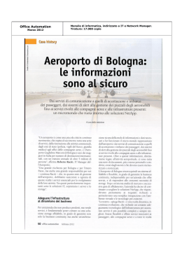
D811414 ver. 03 18/04/06
I
AUTOMAZIONI A PISTONE PER CANCELLI A BATTENTE
GB ELECTROMECHANICAL PISTON FOR SWING GATES
F VERIN ELECTROMECANIQUE POUR PORTAILS A VANTAUX
D ELEKTROMECHANISCHER KOLBEN FÜR FLÜGELTORE
�
������
������
E PISTON ELECTROMECANICO PARA CANCELAS DE BATIENTE
P AUTOMATIZAÇÕES DE PISTÃO PARA PORTÕES DE BATENTE
PHOBOS L BT
ISTRUZIONI D’USO E DI INSTALLAZIONE
INSTALLATION AND USER’S MANUAL
INSTRUCTIONS D’UTILISATION ET D’INSTALLATION
INSTALLATIONS-UND GEBRAUCHSANLEITUNG
INSTRUCCIONES DE USO Y DE INSTALACION
INSTRUÇÕES DE USO E DE INSTALAÇÃO
Via Lago di Vico, 44
36015 Schio (VI)
Tel.naz. 0445 696511
Tel.int. +39 0445 696533
Fax 0445 696522
Internet: www.bft.it
E-mail: [email protected]
D811414_03
2 - PHOBOS L BT Ver. 03
D811414_03
ITALIANO
MANUALE D’USO
Nel ringraziarVi per la preferenza accordata a questo prodotto, la ditta è certa che da
esso otterrete le prestazioni necessarie al Vostro uso. Leggete attentamente l’opuscolo
“Avvertenze” ed il “Libretto istruzioni” che accompagnano questo prodotto in quanto
forniscono importanti indicazioni riguardanti la sicurezza, l’installazione, l’uso e la
manutenzione. Questo prodotto risponde alle norme riconosciute della tecnica e della
disposizioni relative alla sicurezza. Confermiamo che è conforme alle seguenti direttive
europee: 89/336/CEE, 73/23/CEE (e loro modifiche successive).
1) GENERALITÀ
Pistone elettromeccanico progettato per automatizzare cancelli di tipo residenziale.
Il motoriduttore mantiene il blocco in chiusura ed apertura senza necessità di elettroserratura per ante di lunghezza massima di 3m. Per ante di lunghezza compresa tra
3m e 5m l’elettroseratura risulta indispensabile.
L’attuatore è provvisto di limitatore di coppia elettronico. Deve essere comandato da
un quadro comandi elettronico dotato di regolazione di coppia.
Il funzionamento a fine corsa è regolato da due finecorsa elettromeccanici.
L’attuatore è provvisto di un sistema di rilevamento ostacoli secondo le normative
EN12453 e EN 12445.
Sono disponibili i seguenti accessori opzionali:
- Kit batteria tampone mod. BT BAT
Consente il funzionamento dell’automazione anche se manca per un breve periodo
l’alimentazione di rete.
2) SICUREZZA
L’automazione, se installata ed utilizzata correttamente, soddisfa il grado di sicurezza
richiesto.
Tuttavia è opportuno osservare alcune regole di comportamento per evitare inconvenienti accidentali.
• Prima di usare l’automazione, leggere attentamente le istruzioni d’uso e conservarle
per consultazioni future.
• Tenere bambini, persone e cose fuori dal raggio d’azione dell’automazione,in
particolare durante il funzionamento.
• Non lasciare radiocomandi o altri dispositivi di comando alla portata dei bambini
onde evitare azionamenti involontari dell’automazione.
• Non contrastare volontariamente il movimento dell’anta.
• Non modificare i componenti dell’automazione.
• In caso di malfunzionamento, togliere l’alimentazione, attivare lo sblocco di emergenza per consentire l’accesso e richiedere l’intervento di un tecnico qualificato
(installatore).
• Per ogni operazione di pulizia esterna, togliere l’alimentazione di rete.
• Tenere pulite le ottiche delle fotocellule ed i dispositivi di segnalazione luminosa.
Controllare che rami ed arbusti non disturbino i dispositivi di sicurezza (fotocellule).
• Per qualsiasi intervento diretto all’automazione, avvalersi di personale qualificato
(installatore).
• Annualmente far controllare l’automazione da personale qualificato.
3) MANOVRA DI EMERGENZA
Ogni operatore è dotato di sblocco a chiave. Alzato il tappo copriserratura (fig.1), inserire
la chiave di sblocco in dotazione e ruotare di 90° in senso orario.
Spingere manualmente l’anta per aprire il cancello. Per ripristinare il funzionamento
motorizzato, ruotare la chiave al contrario e rimettere il tappo di copertura.
4) MANUTENZIONE E DEMOLIZIONE
La manutenzione dell’impianto va fatta eseguire regolarmente da parte di personale
qualificato.
Se il cavo di alimentazione é danneggiato esso deve essere sostituito dal costruttore
o dal suo servizio assistenza tecnica o comunque da persona con qualifica similare,
in modo da prevenire ogni rischio.
I materiali costituenti l’apparecchiatura e il suo imballo vanno smaltiti secondo le norme
vigenti. Le pile non devono essere disperse nell’ambiente.
The following optional accessories are available on request:
- Buffer battery kit mod. BT BAT
Allows operation of the automation even when there is no mains power supply for a
short period of time.
2) SAFETY
If correctly installed and used, this automation device satisfies the required safety
level standards.
However, it is advisable to observe some practical rules in order to avoid accidental
problems.
• Before using the automation device, carefully read the operation instructions and
keep them for future reference.
• Keep children, people and things outside the automation working area, particularly
during its operation.
• Keep radio control or other control devices out of children’s reach, in order to avoid
any unintentional automation activation.
• Do not intentionally oppose the leaf movement.
• Do not modify the automation components.
• In case of malfunction, disconnect the power supply, activate the emergency release
to have access to the automation and request the assistance of a qualified technician
(installer).
• Before proceeding to any outside cleaning operation, disconnect the power supply.
• Keep the photocell optical components and light signal devices clean.
• Check that the safety devices (photocells) are not obscured by branches or shrubs.
• For any direct assistance to the automation system, request the help of a qualified
technician (installer).
• Have qualified personnel check the automation system once a year.
3) EMERGENCY MANOEUVRE
All controllers feature a key release mechanism. After lifting the lock cover (fig.1), insert
the release key supplied and turn it clockwise by 90°.
Push the leaf manually to open the gate. To reset the motorised operation, turn the key
in the opposite direction and refit the cover.
4) MAINTENANCE AND DEMOLITION
The maintenance of the system should only be carried out by qualified personnel regularly.
If the power supply cable is damaged, it must be replaced by the manufacturer or its
technical assistance service, or else by a suitably qualified person, in order to prevent
any risk.The materials making up the set and its packing must be disposed of according
to the regulations in force.Batteries must be properly disposed of.
WARNINGS
Correct controller operation is only ensured when the data contained in the
present manual are observed. The company is not to be held responsible for
any damage resulting from failure to observe the installation standards
and the instructions contained in the present manual.
The descriptions and illustrations contained in the present manual are not binding. The Company reserves the right to make any alterations deemed appropriate
for the technical, manufacturing and commercial improvement of the product,
while leaving the essential product features unchanged, at any time and without
undertaking to update the present publication.
Fig. 1
AVVERTENZE
Il buon funzionamento dell’operatore è garantito solo se vengono rispettate i dati
riportati in questo manuale. La ditta non risponde dei danni causati dall’inosservanza delle norme di installazione e delle indicazioni riportate in questo manuale.
Le descrizioni e le illustrazioni del presente manuale non sono impegnative.
Lasciando inalterate le caratteristiche essenziali del prodotto, la Ditta si riserva
di apportare in qualunque momento le modifiche che essa ritiene convenienti
per migliorare tecnicamente, costruttivamente e commercialmente il prodotto,
senza impegnarsi ad aggiornare la presente pubblicazione.
ENGLISH
USER’S MANUAL
Thank you for buying this product, our company is sure that you will be more than
satisfied with the product’s performance. The product is supplied with a “Warnings”
leaflet and an “Instruction booklet”. These should both be read carefully as they
provide important information about safety, installation, operation and maintenance.
This product complies with the recognised technical standards and safety regulations.
We declare that this product is in conformity with the following European Directives:
89/336/EEC and 73/23/EEC (and subsequent amendments).
1) GENERAL OUTLINE
Electromechanical piston designed to automate residential gates.
The gearmotor keeps the gate locked on closing and on opening, without needing an
electric lock for leaves up to 3 m long. For leaves ranging between 3m and 5m long,
the electric lock becomes indispensable.The operator is provided with an electronic
torque limiter. It must be controlled by an electronic control panel provided with torque
setting. The end-of-stroke operation is regulated by two electromechanical limit devices.
The operator is provided with an obstacle detection system complying with EN12453
and EN 12445 standards.
PHOBOS L BT Ver. 03 - 3
MANUALE PER L’INSTALLAZIONE
Nel ringraziarVi per la preferenza accordata a questo prodotto, la ditta è
certa che da esso otterrete le prestazioni necessarie al Vostro uso. Leggete attentamente l’opuscolo “Avvertenze” ed il “Libretto istruzioni” che
accompagnano questo prodotto in quanto forniscono importanti indicazioni
riguardanti la sicurezza, l’installazione, l’uso e la manutenzione. Questo
prodotto risponde alle norme riconosciute della tecnica e delle disposizioni
relative alla sicurezza. Confermiamo che è conforme alle seguenti direttive
europee: 89/336/CEE, 73/23/CEE (e loro modifiche successive).
1) SICUREZZA GENERALE
ATTENZIONE! Una installazione errata o un uso improprio del prodotto, può
creare danni a persone, animali o cose.
• Leggete attentamente l’opuscolo ”Avvertenze” ed il ”Libretto istruzioni”
che accompagnano questo prodotto, in quanto forniscono Importanti
indicazioni riguardanti la sicurezza, l’installazione, l’uso e la manutenzione.
• Smaltire i materiali di imballo (plastica, cartone, polistirolo, ecc.) secondo quanto previsto dalle norme vigenti. Non lasciare buste di nylon e
polistirolo a portata dei bambini.
• Conservare le istruzioni per allegarle al fascicolo tecnico e per consultazioni future.
• Questo prodotto è stato progettato e costruito esclusivamente per l’utilizzo
indicato in questa documentazione.
Usi non indicati in questa documentazione potrebbero essere fonte di
danni al prodotto e fonte di pericolo.
• La Ditta declina qualsiasi responsabilità derivante dall’uso improprio o
diverso da quello per cui è destinato ed indicato nella presente documentazione.
• Non installare il prodotto in atmosfera esplosiva.
• Gli elementi costruttivi della macchina devono essere in accordo con
le seguenti Direttive Europee: 89/336/CEE, 73/23/CEE, 98/37 CEE e
loro modifiche successive. Per tutti i Paesi extra CEE, oltre alle norme
nazionali vigenti, per un buon livello di sicurezza è opportuno rispettare
anche le norme sopracitate.
• La Ditta declina qualsiasi responsabilità dall’inosservanza della Buona
Tecnica nella costruzione delle chiusure (porte, cancelli, ecc.), nonché
dalle deformazioni che potrebbero verificarsi durante l’uso.
• L’installazione deve essere in accordo con quanto previsto dalle Direttive Europee: 89/336/CEE, 73/23/CEE, 98/37 CEE e loro modifiche successive.
• Togliere l’alimentazione elettrica, prima di qualsiasi intervento sull’impianto.
Scollegare anche eventuali batterie tampone se presenti.
• Prevedere sulla rete di alimentazione dell’automazione, un interruttore
o un magnetotermico onnipolare con distanza di apertura dei contatti
uguale o superiore a 3,5 mm.
• Verificare che a monte della rete di alimentazione, vi sia un interruttore
differenziale con soglia da 0.03A.
• Verificare se l’impianto di terra è realizzato correttamente: collegare tutte
le parti metalliche della chiusura (porte, cancelli, ecc.) e tutti i componenti
dell’impianto provvisti di morsetto di terra.
• Applicare tutti i dispositivi di sicurezza (fotocellule, coste sensibili, ecc.)
necessari a proteggere l’area da pericoli di schiacciamento, convogliamento, cesoiamento.
• Applicare almeno un dispositivo di segnalazione luminosa (lampeggiante)
in posizione visibile, fissare alla struttura un cartello di Attenzione.
• La Ditta declina ogni responsabilità ai fini della sicurezza e del buon
funzionamento dell’automazione se vengono impiegati componenti di
altri produttori.
• Usare esclusivamente parti originali per qualsiasi manutenzione o riparazione.
• Non eseguire alcuna modifica ai componenti dell’automazione se non
espressamente autorizzata dalla Ditta.
• Istruire l’utilizzatore dell’impianto per quanto riguarda i sistemi di comando
applicati e l’esecuzione dell’apertura manuale in caso di emergenza.
• Non permettere a persone e bambini di sostare nell’area d’azione dell’automazione.
• Non lasciare radiocomandi o altri dispositivi di comando alla portata dei
bambini onde evitare azionamenti involontari dell’automazione.
• L’utilizzatore deve evitare qualsiasi tentativo di intervento o riparazione
e rivolgersi solo a personale qualificato.
• Tutto quello che non è espressamente previsto in queste istruzioni, non
è permesso.
• L’installazione deve essere fatta utilizzando dispositivi di sicurezza e
comandi conformi alla EN 12978.
2) GENERALITA’
Pistone elettromeccanico progettato per automatizzare cancelli di tipo
residenziale.
Il motoriduttore mantiene il blocco in chiusura ed apertura senza necessità di
6 - PHOBOS L BT Ver. 03
elettroserratura per ante di lunghezza massima di 3m. Per ante di lunghezza
compresa tra 3m e 5m l’elettroseratura risulta indispensabile.
L’attuatore è provvisto di limitatore di coppia elettronico. Deve essere comandato da un quadro comandi elettronico dotato di regolazione di coppia.
Il funzionamento a fine corsa è regolato da due finecorsa elettromeccanici.
L’attuatore è provvisto di un sistema di rilevamento ostacoli secondo le
normative EN12453 e EN 12445.
Sono disponibili i seguenti accessori opzionali:
- Kit batteria tampone mod. PHOBOS-BT BAT
Consente il funzionamento dell’automazione anche se manca per un breve
periodo l’alimentazione di rete.
3) DATI TECNICI
3.1) PHOBOS L BT
Alimentazione : .............................................................................. 24V d.c.
Giri motore : ................................................................................3800 min -1
Potenza assorbita : .............................................................................. 40 W
Corrente assorbita : ............................................................................. 1.5 A
Forza di spinta e trazione : ...............................................2000 N (~200 kg)
Corsa utile : .................................................................................... 410 mm
Velocità stelo :........................................................................ 14 mm/s circa
Reazione all’urto :...... Limitatore di coppia integrato su quadro di comando Libra
Finecorsa: ......................................Elettromeccanici incorporati e regolabili
Manovra manuale : .................................................. Chiave CLS di sblocco
N° manovre in 24ore :............................................................... 60 manovre
Massima lunghezza anta senza elettroserratura : ................................. 3 m
Massima lunghezza anta con elettroserratura :..................................... 5 m
Massimo peso anta : ........................................................2500 N (~250 kg)
Condizioni ambientali : .................................................. da -10 °C a +50 °C
Grado di protezione : ...........................................................................IP X4
Dimensioni : .............................................................................. Vedere fig.1
Peso operatore : .........................................................................50N (~5kg)
Lubrificazione : ............................................................. grasso permanente
3.2) KIT BATTERIE BT BAT
Tensione di carica: ....................................................................... 27.2V d.c.
Corrente di carica: ............................................................................ 130mA
Dati rilevati alla temperatura esterna di: .............................................. 25°C
Capacità batteria: ................................................................ 2x (12V 1.2Ah)
Soglia protezione batteria scarica: ................................................. 20.4Vdc
Tempo di ricarica batteria: ............................................................... 12/14 h
4) INSTALLAZIONE DELL’ATTUATORE
4.1) Verifiche preliminari
Controllare:
• Che la struttura del cancello sia sufficientemente robusta.
• In ogni caso, l’attuatore deve spingere l’anta in un punto rinforzato.
• Che le ante si muovano manualmente e senza sforzo per tutta la corsa.
• Che siano installate le battute d’arresto delle ante sia in apertura che in
chiusura.
• Se il cancello non è di nuova installazione, controllare lo stato di usura
di tutti i componenti.
• Sistemare o sostituire le parti difettose o usurate. L’affidabilità e la sicurezza
dell’automazione è direttamente influenzata dallo stato della struttura del
cancello.
In fig.2, è riportato lo schema a cui fare riferimento per l’installazione e la
tabella delle misure per il fissaggio a pilastro.
Lo schema di fig.2 utilizza le seguenti convenzioni:
P
staffa posteriore di fissaggio al pilastro
F
staffa anteriore di fissaggio dell’anta
a-b quote per determinare il punto di fissaggio della staffa “P”
C
valore dell’interasse di fissaggio (C = 805mm)
D
lunghezza del cancello
X
distanza dall’asse del cancello allo spigolo del pilastro
Z
valore sempre superiore a 45 mm (b - X)
kg
peso max dell’anta
α°
angolo d’apertura dell’anta
4.2) Come interpretare la tabella delle misure di installazione
Dalla tabella è possibile scegliere valori di “a” e “b” in funzione dei gradi α°
di apertura che si desiderano ottenere.
Se si utilizzano valori di “a” e “b” troppo diversi tra loro, il movimento dell’anta
non è costante e la forza di trazione o spinta varia durante il movimento.
Per rispettare la velocità di apertura e garantire un buon funzionamento
dell’operatore è opportuno che i valori “a” e “b” siano poco diversi tra loro.
Con valori max di “a” e “b”, il pistone sviluppa la massima forza.
D811414_03
ITALIANO
D811414_03
MANUALE PER L’INSTALLAZIONE
4.3) Accorgimenti per installazioni particolari
In fig.3 è illustrata una installazione con nicchia quando non c’è spazio
sufficiente fra anta e recinzione.
Quando la posizione dell’anta non permette di ottenere un valore di “b”
presente in tabella, in questo caso, è possibile spostare il cardine dell’anta
(fig.4), oppure realizzare una nicchia nel pilastro stesso (fig.5).
4.4) Ancoraggio degli attacchi al pilastro ed all’anta del cancello.
Fissare l’attacco “P” (fig.6) al pilastro con una robusta saldatura.
Allo stesso modo saldare al cancello la staffa “F” facendo attenzione che
l’attuatore da montare risulti parallelo al piano di movimento del cancello
fig.7.
Nel caso di cancelli che si muovono in un piano inclinato (apertura verso
l’interno con vialetto in salita), il pistone consente una oscillazione rispetto
all’asse orizzontale dei valori massimi indicati in fig.7.
• Se il pilastro è in muratura, la piastra “PF” dovrà essere ancorata in
profondità mediante idonee zanche “Z” saldate sul retro della stessa
(fig.8).
• Se il pilastro è di pietra ed il cancello è piccolo, è possibile fissare la
piastra “PF” con quattro tasselli metallici ad espansione “T” (fig.9); se
il cancello non è piccolo è consigliato usare una piastra “PF” di forma
angolare (fig.10).
• ATTENZIONE: La staffa di fissaggio “F” deve essere saldata prima del
montaggio dell’attuatore. Successivamente facendo riferimento alla Fig.7
inserire completamente la boccola “B” nella staffa, posizionare l’anello
distanziale “R”, inserire il perno dell’attuatore e fissare il perno alla staffa
con l’anello “S”.
5) BATTUTE D’ARRESTO DELLE ANTE AL SUOLO
Per il corretto funzionamento dell’attuatore,è obbligatorio utilizzare le battute
di arresto “B” sia in apertura che in chiusura come indicato in fig.11
6) PREDISPOSIZIONE DELL’IMPIANTO ELETTRICO (fig.12).
Predisporre l’impianto elettrico come in fig.12 facendo riferimento alle norme
vigenti per gli impianti elettrici CEI-64-8, IEC 364, armonizzazione HD384
ed altre norme nazionali.
Tenere nettamente separati i collegamenti di alimentazione di rete dai collegamenti di servizio (fotocellule, coste sensibili, dispositivi di comando ecc.).
ATTENZIONE! Per il collegamento alla rete, utilizzare cavo multipolare
di sezione minima 3x1.5mm2 e del tipo previsto dalle normative vigenti.
A titolo di esempio, se il cavo è all’esterno (all’aperto), deve essere
almeno pari a H07RN-F mentre, se all’interno (in canaletta), deve essere
almeno pari a H05 VV-F con sezione 3x1.5mm2.
Realizzare i collegamenti dei dispositivi di comando e di sicurezza in armonia
con le norme per l’impiantistica precedentemente citate.
In fig.12 è riportato il numero di collegamenti e la sezione per una lunghezza
dei cavi di alimentazione fino a 100 metri; per lunghezze superiori, calcolare
la sezione per il carico reale dell’automazione. Quando le lunghezze dei
collegamenti ausiliari superano i 50 metri o passano in zone critiche per i
disturbi, è consigliato disaccoppiare i dispositivi di comando e di sicurezza
con opportuni relè.
I componenti principali per una automazione sono (fig.12):
I
Interruttore onnipolare omologato con apertura contatti di almeno 3,5
mm provvisto di protezione contro i sovraccarichi ed i cortocircuiti,
atto a sezionare l’automazione dalla rete. Se non presente, prevedere
a monte dell’automazione un interruttore differenziale omologato di
adeguata portata e soglia da 0.03A.
Qr
Quadro comando e ricevente incorporata.
S
Selettore a chiave.
AL
Lampeggiante con antenna accordata.
M
Operatore
Fte Coppia fotocellule esterne (parte emittente)
Fre Coppia fotocellule esterne (parte ricevente)
Fti
Coppia fotocellule interne con colonnine (parte emittente)
Fri
Coppia fotocellule interne con colonnine (parte ricevente)
T
Trasmittente 1-2-4 canali
RG58 Cavo per antenna
La connessione tra operatore e quadro comando viene effettuata mediante
tre cavi così identificati:
• rosso
motore +
• nero
motore • bianco
controllo fine corsa
In Fig. 16 è riportato lo schema di collegamento della centrale comando
mod. LIBRA.
Nel caso sia errato il verso di apertura e chiusura è possibile invertire le
ITALIANO
connessioni motore + e motore - (rosso/nero) sul quadro comando.
Il primo comando dopo un’interruzione di rete deve essere di apertura.
Le sezioni ed il numero dei fili sono indicati nel disegno (fig.12); per lunghezze superiori a 100 metri, aumentare la sezione dei fili. Tutte le masse
metalliche dei contenitori delle apparecchiature e degli automatismi devono
essere messe a terra.
7) REGOLAZIONE DELLA FORZA DI SPINTA
ATTENZIONE: Verificare che il valore della forza d’impatto
misurato nei punti previsti dalla norma EN12445, sia inferiore
a quanto indicato nella norma EN 12453.
La forza di spinta viene tarata mediante la regolazione di coppia presente
nel quadro comandi. La coppia ottimale, deve permettere il ciclo completo
di apertura e chiusura con la minima forza necessaria. Una coppia eccessiva, può compromettere la sicurezza antischiacciamento. Al contrario, una
coppia insufficiente può compromettere una corretta manovra. Consultare
il manuale istruzioni del quadro comandi.
8) REGOLAZIONE DEI FINECORSA
La regolazione dei fine corsa viene effettuata mediante il corretto posizionamento dei fine corsa (FC1 e FC2 di Fig.1).
8.1) Regolazione fine-corsa di chiusura (Fig.13):
Portare l’anta nella posizione di chiusura desiderata, allentare le due viti di
fissaggio del finecorsa di chiusura (FC1 di Fig.1) e spostarlo verso la staffa
di fissaggio fino a percepire lo scatto del microinterruttore.
Eseguire una manovra di chiusura per verficare l’esatto intervento del
finecorsa; se l’anta si ferma in anticipo rispetto alla chiusura desiderata,
spostare leggermente il finecorsa verso l’estremità dello stelo, se, invece,
l’anta incontra il fermo a terra di chiusura e l’attuatore inverte il moto, spostare
leggermente il finecorsa verso il corpo dell’attuatore. Dopo aver individuato
il corretto posizionamento del finecorsa, fissarlo con le due viti.
8.2) Regolazione fine-corsa di apertura (Fig.14):
Portare l’anta nella posizione di apertura desiderata, allentare le due viti di
fissaggio del finecorsa di apertura (FC2 di Fig.1) e spostarlo verso la staffa
di fissaggio fino a percepire lo scatto del microinterruttore.
Eseguire una manovra di apertura per verficare l’esatto intervento del finecorsa; se l’anta si ferma in anticipo rispetto all’apertura desiderata, spostare
leggermente il finecorsa verso il corpo dell’attuatore, se, invece, l’anta incontra
il fermo a terra di apertura e l’attuatore inverte il moto, spostare leggermente
il finecorsa verso l’estremità dello stelo. Dopo aver individuato il corretto
posizionamento del finecorsa, fissarlo con le due viti.
N.B. Se viene utilizzato il quadro comandi LIBRA si deve avere l’accortezza di
anticipare leggermente l’intervento dei finecorsa, in quanto lo stelo, dopo aver
intercettato i finecorsa continua a muoversi per circa altri 1-2 cm. (100 ms).
Questo garantisce una perfetta battuta delle ante sugli appoggi a terra.
9) APERTURA MANUALE
Ogni operatore è dotato di sblocco a chiave. Alzato il tappo copriserratura
(fig.15), inserire la chiave di sblocco in dotazione e ruotare di 90° in senso
orario.
Spingere manualmente l’anta per aprire il cancello. Per ripristinare il funzionamento motorizzato, ruotare la chiave al contrario e rimettere il tappo
di copertura.
10) ELETTROSERRATURA
ATTENZIONE: Nel caso di ante di lunghezza superiore a 3m,
risulta indispensabile l’installazione di una elettroserratura.
La Fig.16 riporta un esempio di connessione di una elettroserratura a scatto
ECB 12 Va.c. collegata ad un quadro comando LIBRA.
Il quadro Libra per pilotare l’elettroseratura richiede un’apposita scheda
mod. ME BT.
11) VERIFICA DELL’AUTOMAZIONE
Prima di rendere definitivamente operativa l’automazione, controllare scrupolosamente quanto segue:
• Verificare che tutti i componenti siano fissati saldamente.
• Controllare il corretto funzionamento di tutti i dispositivi di sicurezza
(fotocellule, costa pneumatica, ecc).
• Verificare il comando della manovra di emergenza.
• Verificare l’operazione di apertura e chiusura con i dispositivi di comando
applicati.
PHOBOS L BT Ver. 03 - 7
•
MANUALE PER L’INSTALLAZIONE
Verificare la logica elettronica di funzionamento normale (o personalizzata)
nel quadro comandi.
12) USO DELL’AUTOMAZIONE
Poiché l’automazione può essere comandata a distanza mediante radiocomando o pulsante di Start, è indispensabile controllare frequentemente la
perfetta efficienza di tutti i dispositivi di sicurezza.
Per qualsiasi anomalia di funzionamento, intervenire rapidamente avvalendosi
di personale qualificato.
Si raccomanda di tenere i bambini a debita distanza dal raggio d’azione
dell’automazione.
13) COMANDO
L’utilizzo dell’automazione consente l’apertura e la chiusura del cancello
in modo motorizzato. Il comando può essere di diverso tipo (manuale, con
radiocomando, controllo accessi con badge magnetico, ecc.) secondo le
necessità e le caratteristiche dell’installazione. Per i vari sistemi di comando,
vedere le relative istruzioni.
Gli utilizzatori dell’automazione devono essere istruiti al comando e all’uso.
14) MANUTENZIONE
Per qualsiasi manutenzione all’operatore, togliere alimentazione al sistema.
L’attuatore non richiede manutenzioni periodiche.
• Verificare i dispositivi di sicurezza del cancello e della motorizzazione.
• Controllare periodicamente la forza di spinta ed eventualmente correggere
il valore di coppia elettrica nel quadro comandi.
• Per qualsiasi anomalia di funzionamento non risolta, togliere alimentazione
al sistema e chiedere l’intervento di personale qualificato (installatore).
Nel periodo di fuori servizio, attivare lo sblocco manuale per consentire
l’apertura e la chiusura manuale.
15) RUMOROSITA’
Il rumore aereo prodotto dal motoriduttore in condizioni normali di utilizzo è
costante e non supera i 70dB (A).
16) DEMOLIZIONE
L’eliminazione dei materiali va fatta rispettando le norme vigenti.
Nel caso di demolizione dell’automazione non esistono particolari pericoli
o rischi derivanti dall’automazione stessa.
È opportuno in caso di recupero dei materiali, che vengano separati per
tipologia (parti elettriche - rame - alluminio - plastica - ecc.).
17) SMANTELLAMENTO
Nel caso l’automazione venga smontata per essere poi rimontata in altro
sito, bisogna:
• Togliere l’alimentazione e scollegare tutto l’impianto elettrico.
• Togliere il motoriduttore dalla base di fissaggio.
• Smontare il quadro di comando se separato e tutti i componenti dell’installazione.
• Nel caso alcuni componenti non possano essere rimossi o risultino
danneggiati, provvedere alla loro sostituzione.
18) INCONVENIENTI E RIMEDI
18.1) Funzionamento difettoso del motoriduttore.
a) Verificare con apposito strumento la presenza di tensione ai capi del
motoriduttore dopo il comando di apertura o chiusura.
b) Se il movimento dell’anta, è contrario a quello che dovrebbe essere,
invertire i collegamenti di marcia del motore (motore +rosso/ motore
- nero).
c) Nel caso in cui il cancello arriva in battuta sui fermi a terra e l’attuatore
inverta il moto, significa che i finecorsa non sono stati regolati correttamente. Se il fenomeno si verifica in corrispondenza del fermo di apertura,
spostare il finecorsa di apertura verso il cardine del cancello, fino ad
individuare la posizione corretta (vedi regolazione dei finecorsa).
Se invece, il fenomeno si verifica in corrispondenza del fermo di chiusura,
spostare il fine corsa di chiusura verso verso il tappo dello stelo, fino ad
individuare la posizione corretta. (vedi regolazione dei finecorsa).
18.2) Funzionamento difettoso degli accessori elettrici
Tutti i dispositivi di comando e di sicurezza, in caso di guasto, possono causare
anomalie di funzionamento o blocco dell’automazione stessa.
Per individuare il guasto, è opportuno scollegare uno ad uno tutti i dispositivi
dell’automazione, fino ad individuare quello che causa il difetto.
Dopo averlo riparato o sostituito, ripristinare tutti i dispositivi precedentemente scollegati. Per tutti i dispositivi installati, fare riferimento al rispettivo
manuale istruzione.
8 - PHOBOS L BT Ver. 03
AVVERTENZE
Il buon funzionamento dell’operatore è garantito solo se vengono
rispettate i dati riportati in questo manuale.
La ditta non risponde dei danni causati dall’inosservanze delle norme
di installazione e delle indicazioni riportate in questo manuale.
Le descrizioni e le illustrazioni del presente manuale non sono impegnative.
Lasciando inalterate le caratteristiche essenziali del prodotto, la Ditta
si riserva di apportare in qualunque momento le modifiche che essa
ritiene convenienti per migliorare tecnicamente, costruttivamente
e commercialmente il prodotto, senza impegnarsi ad aggiornare la
presente pubblicazione.
D811414_03
ITALIANO
D811414_03
INSTALLATION MANUAL
Thank you for buying this product, our company is sure that you will be more
than satisfied with the product’s performance. The product is supplied with
a “Warnings” leaflet and an “Instruction booklet”. These should both be
read carefully as they provide important information about safety, installation, operation and maintenance. This product complies with the recognised
technical standards and safety regulations. We declare that this product
is in conformity with the following European Directives: 89/336/EEC and
73/23/EEC (and subsequent amendments).
1) GENERAL SAFETY
WARNING! An incorrect installation or improper use of the product
can cause damage to persons, animals or things.
• The “Warnings” leaflet and “Instruction booklet” supplied with this
product should be read carefully as they provide important information
about safety, installation, use and maintenance.
• Scrap packing materials (plastic, cardboard, polystyrene etc) according
to the provisions set out by current standards. Keep nylon or polystyrene
bags out of children’s reach.
• Keep the instructions together with the technical brochure for future
reference.
• This product was exclusively designed and manufactured for the use
specified in the present documentation. Any other use not specified in
this documentation could damage the product and be dangerous.
• The Company declines all responsibility for any consequences resulting from improper use of the product, or use which is different from that
expected and specified in the present documentation.
• Do not install the product in explosive atmosphere.
• The construction components of this product must comply with the following
European Directives: 89/336/CEE, 73/23/EEC, 98/37/EEC and subsequent amendments. As for all non-EEC countries, the above-mentioned
standards as well as the current national standards should be respected
in order to achieve a good safety level.
• The Company declines all responsibility for any consequences resulting
from failure to observe Good Technical Practice when constructing closing structures (door, gates etc.), as well as from any deformation which
might occur during use.
• The installation must comply with the provisions set out by the following
European Directives: 89/336/CEE, 73/23/EEC, 98/37/EEC and subsequent
amendments.
• Disconnect the electrical power supply before carrying out any work on
the installation. Also disconnect any buffer batteries, if fitted.
• Fit an omnipolar or magnetothermal switch on the mains power supply,
having a contact opening distance equal to or greater than 3,5 mm.
• Check that a differential switch with a 0.03A threshold is fitted just before
the power supply mains.
• Check that earthing is carried out correctly: connect all metal parts for
closure (doors, gates etc.) and all system components provided with an
earth terminal.
• Fit all the safety devices (photocells, electric edges etc.) which are needed
to protect the area from any danger caused by squashing, conveying and
shearing.
• Position at least one luminous signal indication device (blinker) where it
can be easily seen, and fix a Warning sign to the structure.
• The Company declines all responsibility with respect to the automation
safety and correct operation when other manufacturers’ components are
used.
• Only use original parts for any maintenance or repair operation.
• Do not modify the automation components, unless explicitly authorised
by the company.
• Instruct the product user about the control systems provided and the
manual opening operation in case of emergency.
• Do not allow persons or children to remain in the automation operation
area.
• Keep radio control or other control devices out of children’s reach, in
order to avoid unintentional automation activation.
• The user must avoid any attempt to carry out work or repair on the automation system, and always request the assistance of qualified personnel.
• Anything which is not expressly provided for in the present instructions,
is not allow.
• Installation must be carried out using the safety devices and controls
prescribed by the EN 12978 Standard.
2) GENERAL OUTLINE
Electromechanical piston designed to automate residential gates.
The gearmotor keeps the gate locked on closing and on opening, without
needing an electric lock for leaves up to 3 m long. For leaves ranging between
3m and 5m long, the electric lock becomes indispensable.
The operator is provided with an electronic torque limiter. It must be controlled
ENGLISH
by an electronic control panel provided with torque setting.
The end-of-stroke operation is regulated by two electromechanical limit
devices.
The operator is provided with an obstacle detection system complying with
EN12453 and EN 12445 standards.
The following optional accessories are available on request:
- Buffer battery kit mod. PHOBOS-BT BAT
Allows operation of the automation even when there is no mains power
supply for a short period of time.
3) TECHNICAL SPECIFICATIONS
3.1) PHOBOS L BT
Power supply : ................................................................................ 24V d.c.
Motor revolutions : ......................................................................3800 min -1
Absorbed power :................................................................................. 40 W
Absorbed current : ............................................................................... 1.5 A
Push and pull force : .........................................................2000 N (~200 kg)
Working stroke : .............................................................................. 410 mm
Stem speed : ..................................................................... 14 mm/s approx.
Impact reaction : ..........................Torque limiter aboard Libra control board
End-of-stroke limitino devices: . Electromechanical, built-in and adjustable
Manual manoeuvre : .......................................................... CLS release key
No. of manoeuvres in 24hours: ............................................60 manoeuvres
Maximum leaf length without electric lock : ........................................... 3 m
Maximum leaf length with electric lock: ................................................. 5 m
Max. leaf weight : ..............................................................2500 N (~250 kg)
Environmental conditions:..........................................from -10 °C to +50 °C
Protection level : ..................................................................................IP X4
Dimensions : .................................................................................. See fig.1
Controller weight :.......................................................................50N (~5kg)
Lubrication : .................................................................... permanent grease
3.2) BATTERY KIT BT BAT
Charging voltage:......................................................................... 27.2V d.c.
Charging current: .............................................................................. 130mA
Outside temperature when values were measured: ............................ 25°C
Battery capacity: .................................................................. 2x (12V 1.2Ah)
Flat battery protection threshold: .................................................... 20.4Vdc
Battery charging time:................................................................... 12/14 hrs
4) INSTALLATION OF THE ACTUATOR
4.1) Preliminary checks
Check that:
• The gate structure is sufficiently sturdy.
• Also make sure that the actuator pushes against the leaf reinforced section.
• The leaves move manually and without effort all along their stroke.
• The door stop plates are fitted at the end of both closing and opening
strokes.
• If the gate has not been recently installed, check the wear condition of all
components.
• Repair or replace faulty or worn parts.
The automation reliability and safety are directly influenced by the state
of the gate structure.
The diagram in fig. 2 should be used as a reference for installation and
consult the table for the distances in mounting the gate post.
The diagram in fig. 2 uses the following legend:
P
Gate post rear fastening bracket
F
Front leaf fastening bracket
a-b “P” bracket installation value
C
Distance between fixing points (C = 805 mm)
D
Gate length
X
Distance from gate axis to the edge of the post
Z
Always over 45 mm (b - X)
kg
max. weight of leaf
α°
leaf opening in degrees
4.2) How to read the installation distance tables
Select “a” and “b” according to the angle in degrees α° that the gate has
to open.
If there is too large a difference between “a” and “b”, the leaf will not travel
smoothly and the pushing or pulling force will fluctuate during its stroke.
To respect the opening speed and ensure the controller operates correctly,
it is best to keep the difference between “a” and “b” as low as possible.
When “a” and “b” are at their maximum, the piston develops the maximum
force.
PHOBOS L BT Ver. 03 - 9
INSTALLATION MANUAL
4.3) Off-standard installations.
Fig. 3 shows an installation with a recess when there is not sufficient space
between the leaf and perimeter wall.
When the leaf’s position does not allow for an “a” value listed in the table,
the leaf’s hinge pivot can be shifted (fig. 4), or a recess can be made cut out
of the actual gate-post (fig. 5).
4.4) Mounting the brackets to the gate-post and to the gate.
Fix the bracket “P” (fig. 6) to the gate-post with a good welding.
The bracket “F” should be welded in the same way to the gate taking care
that the actuator can then be mounted perfectly horizontal to the line of
travel of the gate fig. 7.
If the gate operates on a slope (opening inwards with an uphill driveway), fig. 7
gives the maximum oscillations of the piston with respect to its horizontal.
• If the gate-post is in brick, the plate “PF” must be set soundly into the
post using adequately sized cramps “Z” welded to the back of the plate
(fig. 8).
• If the gate-port is in stone and the gate is small, the plate “PF” can be
mounted with four metal expansion plugs “T” (fig. 9). If a larger gate is
being installed it would be better to use a corner plate “PF” (fig. 10).
• WARNING!: Fixing bracket “F” must be welded before fitting the operator.
Then, with reference to Fig. 7, fully insert bush “B” in the bracket, position
spacer ring “R”, insert the operator pivot and fix the pivot to the bracket
by means of ring “S”.
5) GROUND GATE STOPS
For the controller to operate correctly the gate stop “B” must be used both
in opening and closing, as shown in fig. 11.
6) THE ELECTRICAL PLANT SET-UP (fig. 12).
Lay out the electrical installation (fig. 16) with reference to the CEI 64-8 and
IEC 364 provisions, complying with the HD 384 and other national standards
in force for electrical installation.
The mains power supply connections must be kept totally separate from the
service connections (photocells, electric edges, control devices etc.).
WARNING! For connection to the mains, use a multipolar cable with
a minimum of 3x1.5mm2 cross section and complying with the previously mentioned regulations. For example, if the cable is out side (in
the open), it has to be at least equal to H07RN-F, but if it is on the inside
(or outside but placed in a plastic cable cannel) it has to be or at least
egual to H05VV-F with section 3x1.5mm2.
Connect the control and safety devices in compliance with the previously
mentioned electrical installation standards.
Fig.12 shows the number of connections and the cross section for power
supply cables having a length of approximately 100 metres; in case of longer
cables, calculate the cross section for the true automation load.
When the auxiliary connections exceed 50-metre lengths or go through
critical disturbance areas, it is recommended to decouple the control and
safety devices by means of suitable relays.
The main automation components are (fig.12):
I
Type-approved omnipolar circuit breaker with at least 3,5 mm contact
opening, provided with protection against overloads and short circuits,
suitable for cutting out automation from the mains. If not already installed,
place a type-approved differential switch with a 0.03A threshold in the
circuit just before the automation system.
Qr
Control panel and incorporated receiver.
S
Key selector
AL Blinker tuned in with antenna
M
Controller
Fte Pair of outside photocells (transmitters)
Fre Pair of outside photocells (receivers)
Fti
Pair of inside photocells with column (transmitters)
Fri
Pair of inside photocells with column (receivers)
T
1-2-4 channel transmitter
RG58 Antenna cable
For the connection from the controller to the control board, three cables have
been provided having the following functions:
• red
motor +
• black
motor • white
end-of-stroke control
Fig. 16 shows the wiring diagram of the LIBRA control unit.
Should the opening or closing direction be incorrect, it is possible to invert
the connections of motor + and motor - (red/black) on the control board.
The first command after an interruption of the power supply should be an
10 - PHOBOS L BT Ver. 03
opening manoeuvre.
The cable sections and numbering are indicated in the diagram (fig. 12).
For distances of over 100 meters, the cable section must be increased. All metal
masses in the housings of equipment and automation must be earthed.
7) ADJUSTING THE PUSHING FORCE
WARNING: Check that the impact force value measured at the
points established by the EN 12445 standard is lower than that
specified in the EN 12453 standard.
The pushing force is calibrated by means of the torque regulator in the
control unit. The optimum torque must allow a complete opening or closing
cycle with the minimum force necessary. An excessive torque can reduce
the anti-crush safety. In the other case, an insufficient torque can impede
the manoeuvres. Consult the control unit’s instruction manual.
8) LIMIT DEVICE ADJUSTMENT
End-of-stroke adjustment is carried out by correctly positioning the limit
devices (FC1 and FC2 in Fig. 1).
8.1) Closing limit device adjustment (Fig. 13):
Bring the leaf to the required closing position, loosen the two closing limit
fixing screws (FC1 in Fig. 1) and move the limit device towards the fixing
bracket until the microswitch is heard clicking.
Carry out a closing manoeuvre to check the exact limit activation point; if the
leaf stops before the required closing point, slightly move the limit device
towards the rod end; if, on the contrary, the leaf reaches the closing ground
stop plate and the operator reverses its movement, slightly move the limit
device towards the operator body. After identifying the correct limit position,
fix the device by means of the two screws.
8.2) Opening limit device adjustment (Fig. 14):
Bring the leaf to the required opening position, loosen the two opening limit
fixing screws (FC2 in Fig. 1) and move the limit device towards the fixing
bracket until the microswitch is heard clicking.
Carry out an opening manoeuvre to check the exact limit activation point;
if the leaf stops before the required opening point, slightly move the limit
device towards the operator body; if, on the contrary, the leaf reaches the
opening ground stop plate and the operator reverses its movement, slightly
move the limit device towards the rod end. After identifying the correct limit
position, fix the device by means of the two screws.
N.B. When using the LIBRA control board, remember to slightly anticipate the
intervention of the limiting devices because the stem, after intercepting the
limiting devices, continues to move for a further 1-2 cm. (100 ms). In this way
a perfect strike of the leaves against the ground supports is guaranteed.
9) MANUAL OPENING
All controllers feature a key release mechanism. After lifting the lock cover
(fig.15), insert the release key supplied and turn it clockwise by 90°.
Push the leaf manually to open the gate. To reset the motorised operation,
turn the key in the opposite direction and refit the cover.
10) ELECTRIC LOCK
WARNING: In the case of leaves longer than 3m, it is
indispensable to install an electric lock.
Fig. 16 shows an example of how a 12 Va.c. ECB electric lock is to be connected to a LIBRA control panel.
In order to control the electric lock, the Libra panel requires an appropriate
ME BT board.
11) CHECKING THE AUTOMATION
Before considering the automation completely operational, the following
checks must be made with great care:
• Check that all the components are firmly anchored.
• Control all the safeties work properly (i.e. photocells, pneumatic skirt, etc.).
• Check the emergency manoeuvre control.
• Check the opening and closing manoeuvres using the controls.
• Check the control unit’s electronic logic in normal (or customised) operation.
12) USE OF THE AUTOMATION
Since the automation may be remote controlled either by radio or a Start
button, it is essential that all safeties are checked frequently.
Any malfunction should be corrected immediately by a qualified specialist.
Keep children at a safe distance from the field of action of the automation.
D811414_03
ENGLISH
D811414_03
INSTALLATION MANUAL
ENGLISH
13) THE CONTROLS
With the automation the gate has a power driven opening and closing. The
controls can come in various forms (i.e. manual, remote controlled, limited
access by magnetic badge, etc.) depending on needs and installation
characteristics. For details on the various command systems, consult the
specific instruction booklets.
Anyone using the automation must be instructed in its operation and controls.
14) MAINTENANCE
When carrying out maintenance operation on the controller, disconnect
it from the mains power supply. The actuator does not require periodical
maintenance operations.
• Check the safety devices of the gate and automation.
• Periodically check the pushing force and correct the value of the electric
torque in the control board if necessary.
• In case of unsolved operation failures, disconnect the unit from the
mains power supply and ask for the intervention of qualified personnel
(installer).
When the unit is out of order, activate the manual release to perform
manual opening and closing manoeuvres.
15) NOISE
The aerial noise produced by the gearmotor under normal operating conditions is constant and does not exceed 70dB(A).
16) SCRAPPING
Materials must be disposed of in conformity with the current regulations.
In case of scrapping, the automation devices do not entail any particular
risks or danger. In case of recovered materials, these should be sorted out
by type (electrical components, copper, aluminium, plastic etc.).
17) DISMANTLING
When the automation system is disassembled to be reassembled on another
site, proceed as follows:
• Disconnect the power supply and the entire electrical installation.
• Remove the gearmotor from its fixing base.
• Disassemble the control panel, if separate, and all installation components.
• In the case where some of the components cannot be removed or are
damaged, they must be replaced.
18) TROUBLES AND SOLUTIONS
18.1) Incorrect operation of gearmotor
a) Check for the presence of power supply to the gearmotor using a suitable
instrument after opening or closing commands have been given.
b) If the moving direction of the leaf is opposite to the right one, invert the
motor running connections (motor +red/ motor - black).
c) Should the gate stop and hit the ground stopping device and the actuator
reverse its moving direction, it means that the limiting devices have not
been adjusted correctly. If this happens on the opening stopping device,
move the opening limiting device towards the hinge of the gate until the
correct position is found(see adjustment of the limiting devices).
If, on the contrary, this happens on the closing stopping device, move the
closing limiting device towards the stem plug until the correct position is
found (see adjustment of the limiting devices).
18.2) Incorrect operation of the electrical accessories
All control and safety devices can cause, in case of failure, malfunctioning
or stoppage of the automation.
To identify the failure, it is advised to disconnect all the devices of the automation one by one until the one causing the problem is found.
After fixing or replacing the defective device, reset all the devices previously
disconnected. Refer to the relevant instruction manual for all the devices
installed on the automation.
WARNINGS
Correct controller operation is only ensured when the data contained
in the present manual are observed. The company is not to be held
responsible for any damage resulting from failure to observe the
installation standards and the instructions contained in the present
manual.
The descriptions and illustrations contained in the present manual are
not binding. The Company reserves the right to make any alterations
deemed appropriate for the technical, manufacturing and commercial
improvement of the product, while leaving the essential product features unchanged, at any time and without undertaking to update the
present publication.
PHOBOS L BT Ver. 03 - 11
D811414_03
Fig. 1
102
FC2 (CLOSE)
FC1 (OPEN)
915
Cu MAX 410 mm
108
55
80
Fig. 2
Z=b-x >45mm
D
b
x
F
α°
a
P
kg
C=805mm
B
(mm)
130
140
150
160
170
180
190
200
210
220
230
240
250
260
A
100
110
120
130
140
150
160
170
180
190
200
210
220
230
103
102
101
100
100
99
98
98
97
97
96
96
95
95
106
105
104
103
102
102
101
101
100
100
99
99
98
98
110
109
108
106
105
104
104
103
103
102
101
101
100
100
112
111
110
109
108
107
107
106
105
104
104
103
102
92
116
113
112
112
111
110
109
108
107
106
105
101
91
118
117
116
114
113
112
111
110
109
108
97
91
121
120
118
117
116
114
113
112
103
95
90
123
122
120
119
118
117
107
100
95
91
126
124
123
121
109
103
99
95
91
124
119
112
106
102
98
95
91
113
109
105
101
98
94
91
107
103
100
97
94
91
103
99
96
94
91
99
97
94
92
Installazioni consigliate / Recommended installation
Installations conseillées / Empfohlene Installationen
Instalaciones aconsejadas / Instalações Aconselhadas
24 - PHOBOS L BT Ver. 03
α°
D811414_03
PHOBOS L BT Ver. 03 - 25
Fig. 9
Fig. 10
D811414_03
Fig. 8
T
Z
PF
PF
Fig. 11
Fig. 12
B
Sx
Dx
B
B
ECB 24 Va.c.
Fig. 13
M
AL
E
S
2
2
mm
1
2x
mm
1,5
3x
M
2
mm
1
4x
Fti
CF
2
1,5
3x
T
Fri
CF
26 - PHOBOS L BT Ver. 03
2
m
1m
4x
mm
3x1m
m2
3x1 2
mm
RG
58
2
x1,5
Fte
mm2
2x1
m 2
2x1 m
,5m 2
m
P
R
Q
I
3x1
,5m
m2
Regolazione fine corsa chiusura
Adjustment of the closing limiting devices
Réglage de la butée de fin de course de fermeture
Einstellung des Schließungs-Endschalters
Regulación del fin de carrera de cierre
Regulação do final de curso de fecho
Regolazione fine corsa apertura
Adjustment of the opening limiting devices
Réglage de la butée de fin de course d’ouverture
Einstellung des Öffnungs-Endschalters
Regulación del fin de carrera de apertura
Regulação do final de curso de abertura
FC1 (OPEN)
FC2 (CLOSE)
Fig. 15
Fig. 16
JP3
1sec
1s 5s
5sec
JP3
Impostazione tempo
attrazione relè
Setting of relay
operation time
Introduction du temps
d’attraction du relais
Einstellung anzugsdauer
relais
Configuración del
tiempo de excitación relé
Definição do tempo
de excitação do relé
ME BT
1 2 3 4 5
ECB 24 Va.c.
LIBRA
JP9
M2
6
7
8
M1
9 01
11 12 13 14 15
24V ~
5
25W max.
N
4
FC
L
3
+
2
FC
1
+
D811414_03
Fig. 14
Fig. 13
24V ~
VSafe
PHOBOS L BT Ver. 03 - 27
Scaricare