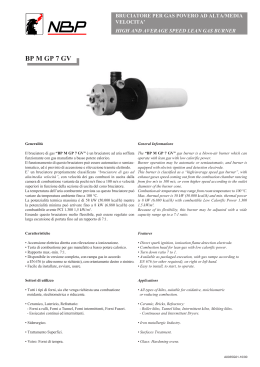
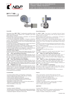
EN Instructions for use Manuale istruzioni per l'uso. GI MIST 1000 DSPNM-D - BRUCIATORI MISTI GAS / OLIO COMBUSTIBILE DENSO A DUE STADI PROGRESSIVI / MODULANTI - TWO STAGES PROGRESSIVE / MODULATING NATURAL GAS / HEAVY OIL MIXED BURNERS ISTRUZIONI ORIGINALI (IT) 0006080766_201004 - Prima di iniziare a usare il bruciatore leggere attentamente quanto esposto nell’opuscolo “AVVERTENZE PER L’UTENTE, PER L’USO IN SICUREZZA DEL BRUCIATORE” presente a corredo del manuale istruzioni, che costituisce parte integrante ed essenziale del prodotto. - Leggere attentamente le istruzioni prima di mettere in funzione il bruciatore o di eseguire la manutenzione. - I lavori sul bruciatore e sull’impianto devono essere eseguiti solo da personale qualificato. - L’alimentazione elettrica dell’impianto deve essere disinserita prima di iniziare i lavori. - Se i lavori non sono eseguiti correttamente si rischiano incidenti pericolosi. - Before using the burner for the first time please carefully read the chapter “WARNINGS NOTES FOR THE USER : HOW TO USE THE BURNER SAFELY” in this instruction manual, which is an integral and essential part of the product. The works on the burner and on the esystem have to be carried out only by competent people. - Read carefully the instructions before starting the burner and service it. - The system electric feeding must be disconnected before starting working on it. - If the works are not carried out correctly it is possible to cause dangerous accidents. 3 / 38 0006080766 ._201004 I T A L I A N O E N G L I S H BALTUR S.p.A. Via Ferrarese 10 - 44042 CENTO (Ferrara) ITALIA Tel. 051.684.37.11 Fax 051.685.75.27/28 (International Tel. ++39.051.684.37.11 - Fax ++39.051.683.06.86) http://www.baltur.it - http://www.baltur.com - E-MAIL [email protected] Dichiarazione di Conformità Dichiariamo che i nostri prodotti BPM...; BGN…; BT…; BTG…; BTL…; TBML...; Comist…; GI…; GI…Mist; Minicomist…; PYR…; RiNOx…; Spark...; Sparkgas...; TBG...;TBL...; TS…; IBR...; IB... (Variante: … LX, per basse emissioni NOx) Descrizione: bruciatori ad aria soffiata di combustibili liquidi, gassosi e misti, domestici e industriali rispettano i requisiti minimi imposti dalle Direttive Europee: 90/396/CEE ...............................................(D.A.G.) 89/336/CEE - 2004/108/CE ........................(C.E.M.) 73/23/CEE – 2006/95/CE ...........................(D.B.T.) 2006/42 CEE .............................................(D.M.) e sono conformi alle Norme Europee: UNI EN 676:2008 (gas e misti, lato gas) UNI EN 267:2002 (gasolio e misti, lato gasolio) Tali prodotti sono pertanto marcati: Dr. Riccardo Fava Amministratore Delegato / CEO Baltur S.p.A. 0085 04/01/2010 ! Avvertenze / note i Informazioni I Pericolo / Attenzione Indice ACCENSIONE E REGOLAZIONE A GAS . .........................................................................................................................................20 ACCENSIONE E REGOLAZIONE CON OLIO COMBUSTIBILE ........................................................................................................15 APERTURA BRUCIATORE - SMONTAGGIO GRUPPO POLVERIZZATORE E DISCO FIAMMA .....................................................35 APPARECCHIATURA DI COMANDO E CONTROLLO PER BRUCIATORI A GAS . ..........................................................................27 AVVERTENZE PER L’UTENTE PER L’USO IN SICUREZZA DEL BRUCIATORE . ...........................................................................2 CARATTERISTICHE TECNICHE . ......................................................................................................................................................4 COLLEGAMENTI ELETTRICI - COLLEGAMENTO DEL BRUCIATORE ALLA TUBAZIONE DEL GAS ............................................7 DESCRIZIONE BRUCIATORI INDUSTRIALI Serie “GI 1000” ............................................................................................................6 DESCRIZIONE DEL FUNZIONAMENTO A METANO . .......................................................................................................................18 DESCRIZIONE DEL FUNZIONAMENTO PRESSOSTATO GAS . ......................................................................................................25 DESCRIZIONE FUNZIONAMENTO CON OLIO COMBUSTIBILE .....................................................................................................10 DESCRIZIONE FUNZIONAMENTO PRESSOSTATO ARIA DIFFERENZIALE ..................................................................................23 FISSAGGIO DEL BRUCIATORE ALLA CALDAIA ...............................................................................................................................6 IMPIANTO DI ALIMENTAZIONE DEL COMBUSTIBILE .....................................................................................................................7 ISTRUZIONI PER VALVOLE GAS ......................................................................................................................................................24 MANUTENZIONE . ..............................................................................................................................................................................22 PARTICOLARE MOTORE SQM 10 E SQM 20 DI COMANDO MODULAZIONE ...............................................................................27 REGOLAZIONE DELL’ARIA SULLA TESTA DI COMBUSTIONE .......................................................................................................22 SCHEMA COLLEGAMENTO POMPA . ...............................................................................................................................................14 SCHEMI ELETTRICI............................................................................................................................................................................75 STRUZIONI REGOLATORE ELETTRONICO MS 30/099 ASCON . ...................................................................................................33 USO DEL BRUCIATORE ....................................................................................................................................................................21 1 / 38 0006080766 ._201004 I T A L I A N O I T A L I A N O ! AVVERTENZE PER L’UTENTE PER L’USO IN SICUREZZA DEL BRUCIATORE PREMESSA Queste avvertenze si propongono di contribuire alla sicurezza nella utilizzazione dei componenti per impianti di riscaldamento ad uso civile e produzione di acqua calda per uso sanitario, mediante l’indicazione di quei comportamenti che é necessario od opportuno adottare al fine di evitare che le loro originarie caratteristiche di sicurezza risultino compromesse da eventuali installazioni non corrette, usi erronei, impropri o irragionevoli. La diffusione delle avvertenze fornite da questa guida mira anche alla sensibilizzazione del pubblico dei “consumatori” ai problemi della sicurezza mediante un linguaggio necessariamente tecnico ma facilmente accessibile. E’ esclusa qualsiasi responsabilità contrattuale ed extracontrattuale del costruttore per i danni causati da errori nell’installazione e nell’uso, e comunque da inosservanza delle istruzioni date dal costruttore stesso. AVVERTENZE GENERALI • ll libretto di istruzioni costituisce parte integrante ed essenziale del prodotto e dovrà essere consegnato all’utente. Leggere attentamente le avvertenze contenute nel libretto in quanto forniscono importanti indicazioni riguardanti la sicurezza di installazione, d’uso e manutenzione. Conservare con cura il libretto per ogni ulteriore consultazione. • L’installazione dell’apparecchio deve essere effettuata in ottemperanza alle norme vigenti, secondo le istruzioni del costruttore a da personale professionalmente qualificato. Per personale professionalmente qualificato si intende quello avente competenza tecnica nel settore dei componenti di impianti di riscaldamento ad uso civile e produzione di acqua calda ad uso sanitario e, in particolare, i centri assistenza autorizzati dal costruttore. Un’errata installazione può causare danni a persone, animali o cose, per i quali il costruttore non é responsabile. • Dopo aver tolto ogni imballaggio assicurarsi dell’integrità del contenuto. In caso di dubbio non utilizzare l’apparecchio e rivolgersi al fornitore. Gli elementi dell’imballaggio (gabbia di legno, chiodi, graffe, sacchetti di plastica, polistirolo espanso, ecc.) non devono essere lasciati alla portata dei bambini in quanto potenziali fonti di pericolo. Inoltre, onde evitare inquinamento, vanno raccolti e depositati in luoghi predisposti allo scopo. • Prima di effettuare qualsiasi operazione di pulizia o di manutenzione, disinserire l’apparecchio dalla rete di alimentazione agendo sull’interruttore dell’impianto e/o attraverso gli appositi organi di intercettazione. • In caso di guasto e/o di cattivo funzionamento dell’apparecchio, disattivarlo, astenendosi da qualsiasi tentativo di riparazione o di intervento diretto. Rivolgersi esclusivamente a personale professionalmente qualificato. L’eventuale riparazione dei prodotti dovrà essere effettuata solamente da un centro di assistenza autorizzato dalla BALTUR utilizzando esclusivamente ricambi originali. Il mancato rispetto di quanto sopra, può compromettere la sicurezza dell’apparecchio. Per garantire l’efficienza dell’ apparecchio e per il suo corretto funzionamento é indispensabile fare effettuare da personale professionalmente qualificato la manutenzione periodica attenendosi alle indicazioni fornite dal costruttore. • Se l’apparecchio dovesse essere venduto o trasferito ad un altro proprietario o se si dovesse traslocare e lasciare l’apparecchio, assicurarsi sempre che il libretto accompagni l’apparecchio in modo che possa essere consultato dal nuovo proprietario e/o dall’installatore. • Questo apparecchio dovrà essere destinato solo all’uso per il quale é stato espressamente previsto: applicato a caldaie, generatori di aria calda, forni o altri focolari simili, situati in luogo riparato dagli agenti atmosferici. Ogni altro uso é da considerarsi improprio e quindi pericoloso. • ll bruciatore deve essere installato in un locale adatto con aperture minime di ventilazione secondo quanto prescritto dalle norme vigenti e comunque sufficienti per ottenere una perfetta combustione • Non ostruire né ridurre la sezione delle griglie di aspirazione dell’aria del bruciatore, e le aperture di aerazione del locale dove é installato un bruciatore o una caldaia, per evitare che si creino situazioni pericolose come la formazione di miscele tossiche ed esplosive. • Prima di collegare il bruciatore accertarsi che i dati di targa siano corrispondenti a quelli della rete di alimentazione (elettrica, gas, gasolio o altro combustibile). • Non toccare parti calde del bruciatore. Queste, normalmente situate in vicinanza della fiamma e dell’eventuale sistema di preriscaldamento del combustibile, diventano calde durante il funzionamento e permangono tali anche dopo un arresto non prolungato del bruciatore. • Allorché si decide di non utilizzare, in via definitiva il bruciatore, si dovranno far effettuare da personale professionalmente qualificato le seguenti operazioni: a) Disinserire l’alimentazione elettrica staccando il cavo di alimentazione dell’interruttore generale. b) Chiudere l’alimentazione del combustibile attraverso la valvola manuale di intercettazione e asportare i volantini di comando dalla loro sede. c) Rendere innocue quelle parti che potrebbero essere potenziali fonti di pericolo. Avvertenze particolari • Accertarsi che, chi ha eseguito l’installazione del bruciatore, lo abbia fissato saldamente al generatore di calore in modo che la fiamma si generi all’interno della camera di combustione del generatore stesso. • Prima di avviare il bruciatore e almeno una volta all’anno, far effettuare da personale professionalmente qualificato le seguenti operazioni: a) Tarare la portata di combustibile del bruciatore secondo la potenza richiesta dal generatore di calore. b) Regolare la portata d’aria comburente per ottenere un valore di rendimento combustione almeno pari al minimo imposto dalle norme vigenti. c) Eseguire il controllo della combustione onde evitare la formazione di incombusti nocivi o inquinanti oltre i limiti consentiti dalle norme vigenti. d) Verificare la funzionalità dei dispositivi di regolazione e di sicurezza. e) Verificare la corretta funzionalità del condotto di evacuazione dei prodotti della combustione. f) Controllare al termine delle regolazioni che tutti i sistemi di bloccaggio meccanico dei dispositivi di regolazione siano ben serrati. g) Accertarsi che nel locale caldaia siano presenti le istruzioni relative all’uso e manutenzione del bruciatore. • In caso di ripetuti arresti in blocco del bruciatore non insistere con le procedure di riarmo manuale, ma rivolgersi a personale professionalmente qualificato per ovviare a tale situazione anomala. • La conduzione e la manutenzione devono essere effettuate esclusivamente da personale professionalmente qualificato, in ottemperanza alle disposizioni vigenti. • Per tutti gli apparecchi con optionals o kit (compresi quelli elettrici) si dovranno utilizzare solo accessori originali. BRUCIATORI 2 / 38 0006080766_201004 ! AVVERTENZE PER L’UTENTE PER L’USO IN SICUREZZA DEL BRUCIATORE ALIMENTAZIONE ELETTRICA • La sicurezza elettrica dell’apparecchio è raggiunta soltanto quando lo stesso è corretamente collegato a un’efficace impianto di messa a terra, eseguito come previsto dalle vigenti norme di sicurezza. E’ necessario verificare questo fondamentale requisito di sicurezza. In caso di dubbio, richiedere un controllo accurato dell’impianto elettrico da parte di personale professionalmente qualificato, poiché il costruttore non é responsabile per eventuali danni causati dalla mancanza di messa a terra dell’impianto. • Far verificare da personale professionalmente qualificato che l’impianto elettrico sia adeguato alla potenza massima assorbita dall’apparecchio, indicata in targa, accertando in particolare che la sezione dei cavi dell’impianto sia idonea alla potenza assorbita dall’apparecchio. • Per l’alimentazione generale dell’apparecchio della rete elettrica, non é consentito l’uso di adattatori, prese multiple e/o prolunghe. • Per l’allacciamento alla rete occorre prevedere un interruttore onnipolare come previsto dalle normative di sicurezza vigenti. • L’alimentazione elettrica del bruciatore deve prevedere il neutro a terra. In caso di controllo della corrente di ionizzazione con neutro non a terra è indispensabile collegare tra il morsetto 2 (neutro) e la terra il circuito RC. • L’uso di un qualsiasi componente che utilizza energia elettrica comporta l’osservanza di alcune regole fondamentali quali: - non toccare l’apparecchio con parti del corpo bagnate o umide e/o a piedi umidi - non tirare i cavi elettrici - non lasciare esposto l’apparecchio ad agenti atmosferici (pioggia, sole, ecc.) a meno che non sia espressamente previsto. - non permettere che l’apparecchio sia usato da bambini o da persone inesperte. • ll cavo di alimentazione dell’apparecchio non deve essere sostituito dall’utente. In caso di danneggiamento del cavo, spegnere l’apparecchio, e, per la sua sostituzione,rivolgersi esclusivamente a personale professionalmente qualificato. • Allorché si decida di non utilizzare l’apparecchio per un certo periodo é opportuno spegnere l’interruttore elettrico di alimentazione a tutti i componenti dell’impianto che utilizzano energia elettrica (pompe, bruciatore, ecc.). ALIMENTAZIONE CON GAS, GASOLIO, O ALTRI COMBUSTIBILI Avvertenze generali • L’installazione del bruciatore deve essere eseguita da personale professionalmente qualificato e in conformità alle norme e disposizioni vigenti, poiché un’errata installazione può causare danni a persone, animali o cose, nei confronti dei quali il costruttore non può essere considerato responsabile. c) che il bruciatore sia alimentato dal tipo di combustibile per il quale é predisposto; d) che la pressione di alimentazione del combustibile sia compresa nei valori riportati in targhetta del bruciatore; e) che l’impianto di alimentazione del combustibile sia dimensionato per la portata necessaria al bruciatore e che sia dotato di tutti i dispositivi di sicurezza e controllo prescritti dalle norme vigenti. • Allorché si decida di non utilizzare il bruciatore per un certo periodo, chiudere il rubinetto o i rubinetti di alimentazione del combustibile. Avvertenze particolari per l’uso del gas • Far verificare da personale professionalmente qualificato: a) che la linea di adduzione e la rampa siano conformi alle norme e prescrizioni vigenti. b) che tutte le connessioni gas siano a tenuta. • Non utilizzare i tubi del gas come messa a terra di apparecchi elettrici. • Non lasciare l’apparecchio inutilmente inserito quando, lo stesso non è utilizzato e chiudere sempre il rubinetto del gas. • In caso di assenza prolungata dell’utente dell’apparecchio chiudere il rubinetto principale di adduzione del gas al bruciatore. • Avvertendo odore di gas: a) non azionare interruttori elettrici, il telefono e qualsiasi altro oggetto che possa provocare scintille; b) aprire immediatamente porte e finestre per creare una corrente d’aria che purifichi il locale; c) chiudere i rubinetti del gas; d) chiedere l’intervento di personale professionalmente qualificato. • Non ostruire le aperture di aerazione del locale dove é installato un apparecchio a gas, per evitare situazioni pericolose quali la formazione di miscele tossiche ed esplosive. CAMINI PER CALDAIE AD ALTO RENDIMENTO E SIMILI E’opportuno precisare che le caldaie ad alto rendimento e simili scaricano nel camino i prodotti della combustione (fumi) a temperatura relativamente bassa. Nella condizione sopra esposta i tradizionali camini, comunemente dimensionati (sezione ed isolamento termico) possono non essere adatti per funzionare correttamente perché il sensibile raffreddamento che i prodotti della combustione subiscono nel percorrere gli stessi consente, molto probabilmente, un abbassamento della temperatura anche al di sotto del punto di condensazione. In un camino che lavori in regime di condensazione si ha presenza di fuliggine allo sbocco in atmosfera quando si brucia gasolio od olio combustibile oppure presenza di acqua di condensa lungo il camino stesso, quando si brucia gas (metano, GPL, ecc.). Da quanto sopra esposto si deve dedurre che i camini collegati a caldaie ad alto rendimento e simili devono essere dimensionati (sezione ed isolamento termico) per l’uso specifico per evitare l’inconveniente sopra descritto. • Prima dell’installazione si consiglia di effettuare una accurata pulizia interna di tutte le tubazioni dell’impianto di adduzione del combustibile onde rimuovere eventuali residui che potrebbero compromettere il buon funzionamento del bruciatore. • Per la prima messa in funzione dell’apparecchio far effettuare da personale professionalmente qualificato le seguenti verifiche: a) il controllo della tenuta nel tratto interno ed esterno dei tubi di adduzione del combustibile; b) la regolazione della portata del combustibile secondo la potenza richiesta al bruciatore; 3 / 38 0006080766 ._201004 I T A L I A N O CARATTERISTICHE TECNICHE GI mist 1000 DSPNM-D MODELLO METANO POTENZA TERMICA PORTATA PRESSIONE INGRESSO AL REGOLATORE MAX kW MIN kW MAX mbar MAX kW 10 500 2 500 1 056 251 500 8kV - 20mA 10 500 MIN kW 2 500 MAX kg/h MIN kg/h 940 224 50° E - 50° C 8kV - 30mA 3N ~ 400V - 50 Hz 22 x 2800 r.p.m 4 x 1400 r.p.m. 26,6 MAX kW MIN kW TRASFORMATORE METANO OLIO COMBUSTIBILE I T A L I A N O POTENZA TERMICA PORTATA VISCOSITA’ MAX COMBUSTIBILE TRASFORMATORE TENSIONE Volt MOTORE VENTOLA kW MOTORE POMPA kW POTENZA ELETTRICA ASSORBITA kW . MATERIALE A CORREDO n° 1 n° 2 n° 1 - Rp 2” n° 2 -1”1/2 X 1500 n° 8 M16 x 72 n° 8 M16 n° 8 M16 FLANGIA FISSAGGIO BRUCIATORE GUARNIZIONE ISOLANTE FILTRO TUBI FLESSIBILI PRIGIONIERI DADI ESAGONALI RONDELLE PIANE *) I preriscaldatori elettrici non sono montati sul bruciatore Gas metano: Hi = 35,80 MJ/m3 = 8550 kcal/h, alle condizioni di riferimento 0° C, 1013 mbar Olio combustibile Hi = 40,19 MJ/kg, = 9600 kcal/kg CARATTERISTICHE TECNICO FUNZIONALI • Bruciatore con alimentazione alternata gas metano/olio combustibile. • Funzionamento a due stadi progressivi di potenza. • Possibilità di funzionamento a modulazione di potenza tramite montaggio sul quadro di comando del regolatore automatico RWF40 (da ordinare a parte assieme al kit di modulazione specifico). • Adatto al funzionamento con ogni tipo di focolare. • Miscelazione aria-gas alla testa di combustione e polverizzazione meccanica ad alta pressione del combustibile tramite ugello. • Possibilità di ottenere ottimi valori di combustione tramite la regolazione dell’aria comburente e della testa di combustione. • Manutenzione facilitata dalla possibilità di sfilare i gruppi di miscelazione e di polverizzazione senza smontare il bruciatore dalla caldaia. • Regolazione della portata minima e massima dell’aria tramite servomotore elettrico con chiusura della serranda in sosta per evitare dispersioni di calore al camino. • A richiesta il bruciatore può essere integrato con un preriscaldatore supplementare dell’olio combustibile funzionante a vapore che consente, a regime, di riscaldare il combustibile con il vapore della caldaia, ottenendo così un risparmio d’energia elettrica. • Controllo tenuta valvole secondo normativa europea EN676. • Predisposto per commutazione automatica del combustibile. • Corredato di 1 guarnizione isolante per il fissaggio alla caldaia, 2 tubi flessibili, 1 filtro di linea autopulente con resistenza; ugello non a corredo da ordinare a parte a seconda della portata richiesta. • A richiesta: preriscaldatore a vapore. 4 / 38 0006080766_201004 DIMENSIONI DI INGOMBRO N° 0002670552 I T A L I A N O Mod. GI mist 1000 DSPNM-D A A1 A2 B 1465 800 665 1257 B1 B2 B3 B4 B5 B6 C D EØ 855 402 450 575 175 163 2350 440 480 Mod. FØ G G1 LØ M NØ P Q R S GI mist 1000 DSPNM-D 685 DN80 Rp1/2 630 M16 495 740 1910 1575 795 5 / 38 0006080766 ._201004 CAMPO DI LAVORO Pressione in camera di combustione I T A L I A N O Gasoliol Olio combustibile Potenza termica - DESCRIZIONE BRUCIATORI INDUSTRIALI Serie “GI 1000” Il bruciatore “GI 1000” è in versione monoblocco ed è costituito da gruppi forniti separatamente, il collegamento tra questi componenti deve essere realizzato sul posto di installazione del bruciatore, rispettando le disposizioni BALTUR. A - Testa di combustione con elettroventilatore B - Quadro elettrico C - Centralina di spinta per i combustibili liquidi. Nel caso si utilizzi olio combustibile, questo gruppo comprende anche il preriscaldatore elettrico dell’olio combustibile e, a richiesta, anche un preriscaldatore ausiliario a vapore. D - Gruppo valvole gas per i bruciatori che utilizzano combustibile gassoso (normalmente metano). I bruciatori sono previsti in versioni diverse in funzione del tipo di combustibile impiegato; - GAS (Metano) versione GI 1000 DSPGN - GASOLIO versione GI 1000 DSPG - OLIO COMBUSTIBILE (viscosità nominale max. 50°E a 50°C) versione GI 1000 DSPN-D - GAS (Metano) / OLIO COMBUSTIBILE (viscosità nominale max. 5°E a 50°C) versione GI-MIst 1000 DSPNM - GAS (Metano) / GASOLIO versione GI-Mist 1000 DSPGM Precisiamo che i bruciatori GI-Mist 1000 DSPGM e GI-Mist 1000 DSPNM sono previsti per funzionamento alternativo con il metano oppure con il combustibile liquido. - Il bruciatore serie “GI 1000” è modulante con campo di modulazione da 1 ÷ 4. L’adattamento al momentaneo fabbisogno termico si ottiene mediante un servomotore che regola in maniera combinata la quantità di aria comburente e di combustibile su comando della sonda in caldaia. Il bruciatore è dotato di un dispositivo che varia automaticamente la sezione di passaggio dell’aria nella testa di combustione, in modo proporzionale alla variazione del carico. Con tale dispositivo si può avere un’ottima combustione in tutte le condizioni di carico, perché si ottimizza la miscelazione aria/ combustibile; ne deriva pertanto un minore eccesso di aria con una migliore qualità della combustione. FISSAGGIO DEL BRUCIATORE ALLA CALDAIA - Forare la piastra di ferro della caldaia rispettando la dima di foratura, - Fissare i prigionieri forniti a corredo. E’ consigliabile saldare elettricamente i prigionieri dalla parte interna della piastra per evitare, in caso di smontaggio del bruciatore, la loro estrazione. - Se la piastra non è provvista di isolamento termico è necessario interporre tra la stessa e la caldaia una protezione isolante con spessore di almeno 10 mm. Accertarsi che la testa di combustione penetri nel focolare nella misura richiesta dal costruttore della caldaia. 6 / 38 0006080766_201004 essere verificata prima del collaudo del bruciatore. COLLEGAMENTI ELETTRICI E’ consigliabile che tutti i collegamenti siano eseguiti con filo elettrico flessibile. Le linee elettriche devono essere distanziate dalle parti calde. Assicurarsi che la linea elettrica a cui si vuol collegare l’apparecchio sia alimentata con valori di tensione e frequenza adatti al bruciatore. Assicurarsi che la linea principale, il relativo interruttore con fusibili (indispensabile) e l’eventuale limitatore, siano adatti a sopportare la corrente massima assorbita dal bruciatore. Per i dettagli si vedano gli schemi elettrici specifici per ogni singolo bruciatore. COLLEGAMENTO DEL BRUCIATORE ALLA TUBAZIONE DEL GAS Dopo aver fissato il bruciatore alla caldaia, tenere presente che la bocca del bruciatore deve penetrare in camera di combustione nella quantità richiesta del costruttore della caldaia, si provvede a collegarlo alla tubazione del gas. Raccomandiamo di installare sulla tubazione, più vicino possibile al bruciatore, un raccordo a coppia di flange disposte in modo da consentire, senza difficoltà, l’apertura del portellone di caldaia e/o lo smontaggio del bruciatore. Prima di chiudere questo raccordo occorre, con le cautele del caso e con porte e finestre aperte, effettuare lo spurgo dell’aria contenuta nella tubazione. La perfetta ermeticità della tubazione del gas deve IMPIANTO DI ALIMENTAZIONE DEL COMBUSTIBILE La pompa del bruciatore deve ricevere il combustibile da un adatto circuito di alimentazione con pompa ausiliaria con pressione regolabile da 0,5 ÷ 2 bar, se si usa combustibile con viscosità nominale superiore a 5° E a 50° C, lo stesso deve essere già preriscaldato a 50 ÷ 60° C. Il valore della pressione di alimentazione del combustibile alla pompa del bruciatore (0,5 ÷ 2 bar) deve essere praticamente costante sia con bruciatore fermo che con bruciatore funzionante alla massima erogazione di combustibile richiesta dalla caldaia. Il circuito di alimentazione deve essere realizzato come da nostri disegni, di seguito riportati, anche quando si impiega combustibile con bassa viscosità. Il dimensionamento delle tubazioni deve essere effettuato in funzione della lunghezza delle stesse e della portata della pompa impiegata. Le nostre disposizioni riguardano solo quanto necessario per assicurare un buon funzionamento. Le prescrizioni da osservare per essere in regola con la Legge n° 615 (antismog) e con la circolare del Ministero Degli Interni n° 73 del 29/07/71 nonchè con quanto disposto dal locale Comando dei Vigili del Fuoco, devono essere ricercate nelle pubblicazioni specifiche. DIAGRAMMA VISCOSITÀ’ - TEMPERATURE VISCOSITA' Limite di pompaggio Campo di viscosità per la polverizzazione TEMPERATURE 7 / 38 0006080766 ._201004 Curva 1 " 2 " 3 " 4 " 5 " 6 " 7 " 8 " 9 " 10 Gasolio Extrafluido Fluido 3/5 Fluido 5/7 denso 8 Denso 15 - 20 Denso viscosità Denso viscosità Denso viscosità Denso viscosità 24 35 50 85 a 50° C a 50° C a 50° C a 50° C I T A L I A N O N° 0002901180 SCHEMA CIRCUITO IDRAULICO DI ALIMENTAZIONE PER UNO O PIU’ BRUCIATORI MODULANTI A OLIO COMBUSTIBILE CON VISCOSITA’ NOMINALE MAX (5° E A 50° C) AL BARILOTTO DEGASATORE VEDI 0002901140 1 2 3 4 5 6 AL BARILOTTO DEGASATORE VEDI 0002901140 - CISTERNA PRINCIPALE - FILTRO - POMPA DI CIRCOLAZIONE - BY-PASS (NORMALMENTE CHIUSO) - REGOLATORE DI PRESSIONE REGOLABILE 0,2 - 1 bar - MANOMETRO (0 - 4 bar) AL BARILOTTO DEGASATORE VEDI 0002901140 N.B. I SERBATOI DI RECUPERO COMBUSTIBILE E DEGASATORE (DIAMETRO 150 mm ALTEZZA 400 mm) DEVONO ESSERE INSTALLATI IL PIU’ VICINO POSSIBILE AL BRUCIATORE AD UNA QUOTA SUPERIORE DI ALMENO 0,5 m RISPETTO ALLA POMPA DELLO STESSO. SCHEMA CIRCUITO IDRAULICO DI ALIMENTAZIONE PER UNO O PIU’ BRUCIATORI MODULANTI A OLIO COMBUSTIBILE CON VISCOSITA’ NOMINALE MAX (15° E A 50° C) N° 0002901190 I T A L I A N O AL BARILOTTO DEGASATORE VEDI 0002901140 1 2 3 4 5 6 7 AL BARILOTTO DEGASATORE VEDI 0002901140 AL BARILOTTO DEGASATORE VEDI 0002901140 CISTERNA PRINCIPALE SERPENTINA DI RISCALDAMENTO OLIOCOMB., A VAPORE O ACQUA CALDA FILTRO N.B. I SERBATOI DI RECUPERO COMBUSTIBILE E POMPA DI CIRCOLAZIONE DEGASATORE (DIAMETRO 150 mm ALTEZZA BY-PASS (NORMALMENTE CHIUSO) 400 mm) DEVONO ESSERE INSTALLATI IL REGOLATORE DI PRESSIONE REGOLABILE 0,5 - 2 bar PIU’ VICINO POSSIBILE AL BRUCIATORE AD MANOMETRO (0 - 4 bar) UNA QUOTA SUPERIORE DI ALMENO 0,5 m CAVO ELETTRICO SCALDANTE (SE NECESSARIO) RISPETTO ALLA POMPA DELLO STESSO. 8 / 38 0006080766_201004 N° 0002901200 SCHEMA CIRCUITO IDRAULICO DI ALIMENTAZIONE PER UNO O PIU’ BRUCIATORI MODULANTI A OLIO COMBUSTIBILE DENSO CON VISCOSITA’ NOMINALE MAX (50° E a 50° C) CON RISCALDATORE AUSILIARIO AL BARILOTTO DEGASATORE VEDI 0002901140 1 2 3 4 5 6 7 8 9 10 11 12 AL BARILOTTO DEGASATORE VEDI 0002901140 CISTERNA PRINCIPALE SERPENTINA DI RISCALDAMENTO OLIO COMB., A VAPORE OD ACQUA CALDA FILTRO POMPA DI CIRCOLAZIONE SERPENTINA A VAPORE O ACQUA CALDA PER RISCALDANENTO OLIO COMB. RISCALDATORE AUSILIARIO RESISTENZA TERMOMETRO BARILOTTO DIAMETRO 100 mm ALTEZZA 300 mm BY-PASS (NORMALMENTE CHIUSO) - REGOLATORE DI PRESSIONE REGOLABILE 0,5 - 2 bar MANOMETRO (0 - 4 bar) CAVO ELETTRICO SCALDANTE (SE NECESSARIO) 9 / 38 0006080766 ._201004 N.B. I SERBATOI DI RECUPERO COMBUSTIBILE E DEGASATORE (DIAMETRO 150 mm ALTEZZA 400 mm) DEVONO ESSERE INSTALLATI IL PIU’ VICINO POSSIBILE AL BRUCIATORE AD UNA QUOTA SUPERIORE DI ALMENO 0,5 m RISPETTO ALLA POMPA DELLO STESSO. I T A L I A N O SCHEMA CIRCUITO IDRAULICO N° 0002901140 I T A L I A N O NON DEVE ESSERE INTERPOSTO NESSUN DISPOSITIVO DI INTERCETTAZIONE COLLEGAMENTO AL CIRCUITO DI ALIMENTAZIONE 0002901180, 0002901190, 0002901200 FORNITURA BALTUR 1 2 3 4 5 6 FILTRO TUBO FLESSIBILE POMPA BRUCIATORE (20-22BAR) MANOMETRO 0-40BAR SERVOMOTORE DI MODULAZIONE DISCO CON VITI DI REGOLAZIONE EROGAZIONE ARIA/COMBUSTIBILE 7 DISCO CON VITI DI REGOLAZIONE PER APERTURA E CHIUSURA ARIA ALLA TESTA 8 PRESSOSTATO ARIA 9 TERMOSTATO RITORNO UGELLO 10 REGOLATORE PRESSIONE RITORNO MIN-10 - 12 bar MAX 1820 bar 11 MANOMETRO 0-40BAR 12 PRERISCALDATORI ELETTRICI DESCRIZIONE FUNZIONAMENTO CON OLIO COMBUSTIBILE (Vedi 0002900311) Chiudere l’interruttore sezionatore generale “Q1”, si illumina la spia presenza tensione, e si inseriscono le resistenze ausiliarie della pompa, del filtro, del gruppo polverizzatore e della valvola regolatrice (solo per versione ..N-D). Chiudere l’interruttore marcia/arresto “S1”, la tensione raggiunge l’apparecchiatura “LFL...” al morsetto “1” e i termostati di regolazione del preriscaldatore. La tensione attraversa i contatti degli stessi e raggiunge le bobine dei teleruttori delle resistenze “KR1” e “KR2” che chiudendosi portano corrente alle resistenze dei preriscaldatori che scaldano il combustibile contenuto negli stessi. I termostati di minima del preriscaldatore si chiudono quando la 13 TERMOSTATO DI MINIMA PRERISCALDATORE 14 TERMOSTATO DI MASSIMA PRERISCALDATORE 15 VALVOLA DI SCARICO ARIA / GAS, NORMALMENTE CHIUSA, APRIRE LEGGERMENTE SOLO IN CASO DI SCARICO GAS 16 FILTRO AUTOPULENTE 0,3MM 17 MANOMETRO 0-40BAR 18 SONDA TERMOSTATO (PT100) E TERMOMETRO 19 VALVOLA DI SICUREZZA PRERISCALDATORE (REGOLATA A 32BAR) 20 RIDUTTORE O STABILIZZATORE DI PRESSIONE (PILOTA) 21 PRESSOSTATO GAS MINIMA E MASSIMA CON PRESE DI PRESSIONE (PILOTA) 22 VALVOLA GAS DI SICUREZZA FIAMMA D’ACCENSIONE (PILOTA) 23 VALVOLA GAS PRINCIPALE PER LA FIAMMA D’ACCENSIONE 24 VALVOLA DI NON RITORNO 25 SCARICO ARIA-GAS NORMALMENTE CHIUSA 26 SERBATOIO RECUPERO COMBUSTIBILE E DEGASATORE CON RESISTENZA - - - - TUBAZIONE A CURA DELL’INSTALLATORE temperatura raggiunge il valore a cui gli stessi sono regolati, inserendo così l’apparecchiatura tramite la linea pressostatica. L’apparecchiatura a relè ciclico, svolge il programma di accensione mettendo in funzione il motore del ventilatore per effettuare la fase di preventilazione. Se la pressione dell’aria fornita dalla ventola è sufficiente per far intervenire il relativo pressostato, si inserisce subito, anche il motore della pompa che effettua la precircolazione dell’olio caldo nei condotti del bruciatore. Dalla pompa l’olio raggiunge il preriscaldatore, lo attraversa riscaldandosi alla temperatura prevista ed esce attraverso un filtro per raggiungere il gruppo polverizzatore. L’olio caldo circola nel gruppo polverizzatore senza uscire dall’ugello perchè i passaggi verso l’ugello (andata) e dall’ugello (ritorno) sono 10 / 38 0006080766_201004 chiusi. La chiusura è realizzata mediante “spilli di chiusura” applicati all’estremità delle aste. Detti “spilli” sono premuti, contro le sedi, da robuste molle situate all’estremità opposta delle aste. L’olio circola ed esce dal ritorno del gruppo polverizzatore, attraverso il pozzetto dove è inserito il termostato TRU, e arriva al regolatore di pressione di ritorno, lo attraversa e raggiunge il ritorno della pompa e, da questa, si scarica nel ritorno. La sopra descritta circolazione di olio caldo si effettua ad un valore di pressione un po’ più alta (qualche bar) rispetto alla pressione minima a cui è regolato il regolatore della pressione di ritorno (10 ÷ 12 bar). Questa fase di preventilazione dell’olio ha una durata di 22,5 secondi.Detto tempo può essere prolungato (teoricamente all’infinito) perché una particolare realizzazione del circuito elettrico non consente, di proseguire nello svolgimento del programma di accensione, fino a quando la temperatura del combustibile, nella tubazione di ritorno dall’ugello, ha raggiunto il valore a cui il termostato TRU (Termostato sul Ritorno dell’Ugello) è regolato. Questa particolare realizzazione non consente al combustibile di attraversare l’ugello fino a quando il combustibile stesso raggiunge almeno la temperatura a cui il termostato TRU è regolato. Normalmente l’intervento del termostato TRU avviene entro il normale tempo di preventilazione (37,5 secondi) in caso contrario le fasi di pre-ventilazione e pre-circolazione dell’olio combustibile vengono prolungate fino all’intervento del TRU. L’intervento del TRU, (olio in circolo sufficientemente caldo) consente all’apparecchiatura di proseguire nello svolgimento del programma d’accensione inserendo il trasformatore d’accensione, successivamente, le valvole della fiamma di accensione a gas (pilota). L’alta tensione tra elettrodo e la massa di un bruciatore, innesca la scarica elettrica (scintilla) per l’accensione della miscela gas/aria. L’erogazione è regolata dal regolatore di portata incorporato in una delle due valvole della fiamma di accensione (pilota). La presenza della fiamma è rilevata dalla fotocellula UV. ! Se la fotocellula UV non rileva la fiamma, il bruciatore termina in blocco. Quando più bruciatori funzionano nella stessa camera di combustione, occorre evitare che la fotocellula UV di un bruciatore rilevi la fiamma dell’altro bruciatore. Questa condizione è ottenuta installando la fotocellula su un supporto brandeggiabile, per poter orientare opportunamente la stessa evitando l’interferenza sopra descritta. Dopo 2,5 secondi dall’accensione della fiamma pilota, l’apparecchiatura porta tensione al magnete che mediante opportuni leverismi, fa arretrare le due aste di intercettazione del flusso (andata e ritorno) del combustibile all’ugello. L’arretramento delle aste determina anche la chiusura del passaggio (by-pass) interno al gruppo polverizzatore, di conseguenza la pressione in pompa si porta al valore normale di circa 20 ÷ 22 bar. Lo scostamento delle due aste, dalle sedi di chiusura, consente al combustibile di entrare, ora, nell’ugello alla pressione, regolata alla pompa, di 20 ÷ 22 bar e uscire dall’ugello adeguatamente polverizzato. La pressione di ritorno, che determina l’erogazione in focolare, è regolata dal regolatore di pressione di ritorno. Per la portata di accensione (erogazione minima) detto valore è di circa 10 ÷ 12 bar. Il combustibile polverizzato che esce dall’ugello, si miscela all’aria fornita dalla ventola e viene acceso dalla fiamma pilota a gas già presente. Dopo l’inserzione del magnete viene disinserita la fiamma pilota e il bruciatore è acceso al minimo della modulazione. L’aumento dell’erogazione avviene automaticamente ed in modo continuo, su comando della sonda di modulazione installata sulla caldaia mediante un servomotore. Il motore di modulazione comanda l’aumento dell’erogazione contemporanea del combustibile e dell’aria comburente. L’aumento dell’erogazione del combustibile viene determinato dal disco con profilo variabile che, ruotando, realizza una maggior compressione della molla del regolatore della pressione di ritorno e quindi un aumento della pressione di ritorno corrisponde a un aumento di erogazione del combustibile. All’aumento dell’erogazione del combustibile deve corrispondere un aumento, in quantità adeguata, dell’aria di combustione. Questa condizione viene realizzata all’atto della prima regolazione, agendo sulle viti che variano il profilo del disco di comando della regolazione dell’aria di combustione. L’erogazione del combustibile e contemporaneamente dell’aria comburente, aumenta fino al valore massimo (pressione del combustibile al regolatore della pressione di ritorno pari a circa 18 ÷ 20 bar) se la pressione alla pompa è al valore di 20 ÷ 22 bar. L’erogazione di combustibile e di aria comburente resta al valore massimo fino a quando la temperatura (pressione se caldaia a vapore) della caldaia si avvicina al valore regolato e determina il richiamo del motore di comando della modulazione in senso inverso al movimento precedente. Il movimento di ritorno del motore di modulazione determina una riduzione dell’erogazione di combustibile e della relativa aria di combustione. Il sistema di modulazione raggiunge una posizione di equilibrio corrispondente ad una erogazione di combustibile e della relativa aria di combustione pari alla quantità di calore richiesta dalla caldaia. Con il bruciatore funzionante la sonda in caldaia avverte le variazioni di carico della caldaia ed automaticamente richiede l’adeguamento dell’erogazione di combustibile e della relativa aria comburente al motore di modulazione. Se anche con l’erogazione minima di combustibile e di aria comburente si raggiunge la temperatura (pressione se caldaia a vapore) massima interviene, al valore a cui è regolato, il termostato (pressostato se caldaia a vapore) che determina l’arresto completo del bruciatore. Riabbassandosi la temperatura (pressione se caldaia a vapore), al di sotto del valore di intervento del dispositivo di arresto, il bruciatore ritorna ad accendersi come precedentemente descritto. Tenere presente che il campo di variazione della portata realizzabile, con buona combustione, è indicativamente da 1 a 1/3 rispetto alla portata massima di targa. Nel caso in cui la fiamma non compare entro due secondi dall’inserzione della fiamma pilota,l’apparecchiatura di controllo si mette in “blocco” (arresto completo del bruciatore e accensione della relativa spia di segnalazione). Per “sbloccare” l’apparecchiatura occorre premere il pulsante apposito. ! Il pressostato dell’aria deve essere regolato all’accensione del bruciatore, in funzione del valore di pressione che si riscontra per il funzionamento con fiamma di accensione. 11 / 38 0006080766 ._201004 I T A L I A N O CARATTERISTICHE APPARECCHIATURA Apparecchiatura e relativo programmatore LFL 1.335 Relè ciclico Tempo di sicurezza in secondi 2,5 Tempo di preventilazione e precircolazione in secondi Pre-accensione in secondi Post-accensione in secondi Tempo fra 1° fiamma e inizio modulazione in secondi 37,5 5 2,5 12,5 PARTICOLARE BRUCIATORE CON GRUPPO POLVERIZZATORE, SERVOMOTORE MODULAZIONE, REGOLATORE PRESSIONE DI RITORNO, REGOLATORE SERRANDA ARIA CON BRUCIATORE PILOTA A GAS G.P.L. O METANO N° 0002900312 I T A L I A N O REGOLATORE PRESSIONE RITORNO MIN = 10 + 12 bur MAX = 18 + 20 bur PER VERSIONE ...D TERMOSTAT0 T R U COLLEGAMENTO AL CIRCUITO DI ALIMENTAZIONE VEDI 0002901120 PER UNO O PIU' BRUCIATORI INGRESSO GAS RAMPA PILOTA 100 mbar NE (PILOTA) 18 PRESSOSTATO GAS MINIMA E MASSIMA RAMPA PILOTA 19 REGOLATORE DI PRESSIONE CON FILTRO INCORPORATO 20 TERMOSTATO RITORNO UGELLO (T.R.U.) SOLO PER VERSIONE AD OLIO COMBUSTIBILE 1 2 3 4 5 6 7 8 9 10 11 12 13 14 15 16 17 FILTRO POMPA BRUCIATORE (20-22BARI MANOMETRO O-40 BAR CORPO POLVERIZZATORE UGELLO A RITORNO SENZA SPILLO ASTE CON SPILLI DI CHIUSURA FORI DI BY PASS MOLLE DI CHIUSURA ELETTROMAGNETE DI APERTURA REGOLATORE PRESSIONE RITORNO MIN = 10-12 BAR MAX=18-20 BAR SERVOMOTORE DI MODULAZIONE DISCO COMANDO REGOLAZIONE ARIA / COMBUSTIBILE SERRANDE ARIA TUBO FLESSIBILE PILOTA DI ACCENSIONE VALVOLA GAS PRINCIPALE PER LA FIAMMA DI ACCENSIONE CON REGOLATORE DI PORTATA (PILOTA) VALVOLA GAS DI SICUREZZA PER LA FIAMMA DI ACCENSIO- 12 / 38 0006080766_201004 N° 0002933990 PARTICOLARE VALVOLA DI REGOLAZIONE PRESSIONE DEL COMBUSTIBILE 3 1 2 1 Corpo valvola 2 Tappo accesso vite di regolazione 5 3 Manometro 0 - 40 bar 4 Al ritorno della pompa 4 5 Dal ritorno gruppo polverizzatore N° 0002932080 PARTICOLARE VALVOLA REGOLAZIONEPRESSIONE DEL COMBUSTIBILE PER CIRCUITO AUSILIARIO 1 2 3 4 5 - - - - - Corpo valvola Tappo di sostegno vite regolazione Dado di bloccaggio vite di regolazione Vite di regolazione Bussola di centraggio molla 6 - 7 - 8 - 9 - 10 - 13 / 38 0006080766 ._201004 Molla Otturatore Attacco manometro Ingresso combustibile Uscita combustibile I T A L I A N O UGELLO (CB) CHARLES BERGONZO SMONTATO (SENZA SPILLO) Dati di identificazione ugello: Erogazione in Kg/h Angolo di spruzzo (30°-45°-60°-80°) Rapporto di erogazione (1/3 = B3 – 1/5 = B5) Anello di tenuta in Viton (resistente ail’olio e alta temperatura) BT 9353/1 Camera di turbolenza Ingresso combustibile Foro uscita combustibile Ritorno combustibile Foro di ritorno combustibile N.B. Per un buon funzionamento dell’ugello è indispensabile che il «ritorno» dello stesso non sia mai completamente chiuso. Questa condizione deve essere realizzata operando opportunamente quando si effettua la prima accensione del bruciatore. In pratica occorre che, quando I’ugello lavora alla massima erogazione desiderata, la differenza di pressione tra “mandata” all’ugello (pressione pompa) e “ritorno” dall’ugello (pressione al regotatore di pressione di ritorno) sia almeno di 2 ÷ 3 bar. Esempio Pressione pompa 20 bar Pressione ritorno 20 - 2 = 18 bar Pressione ritorno 20 - 3 = 17 bar Pressione pompa 22 bar Pressione ritorno 22 - 3 = 19 bar Pressione ritorno 22 - 2 = 20 bar SCHEMA COLLEGAMENTO POMPA HP MODELLO VBH 1000 ÷ 6000 Ritorno Mandata Rubinetto Vite regolazione pressione N° 0002900430 I T A L I A N O Aspirazione Manometro 14 / 38 0006080766_201004 ACCENSIONE E REGOLAZIONE CON OLIO COMBUSTIBILE 1) Verificare che le caratteristiche dell’ugello (erogazione ed angolo di spruzzo) siano adeguate al focolare (vedi BT 9353) in caso contrario sostituire l’ugello con altro adatto. 2) Verificare che ci sia combustibile in cisterna e che lo stesso sia, almeno visivamente, adatto per il bruciatore. 3) Verificare che ci sia acqua in caldaia e che le saracinesche dell’impianto siano aperte. 4) Verificare con assoluta certezza, che lo scarico dei prodotti della combustione possa avvenire liberamente (serranda caldaia e camino aperte). 5) Verificare che la tensione della linea elettrica a cui ci si deve collegare, corrisponda a quella richiesta dal bruciatore e che i collegamenti elettrici dei motori e delle resistenze siano correttamente predisposti per il valore di tensione disponibile. Verificare che tutti i collegamenti elettrici realizzati sul posto, siano correttamente eseguiti come da nostro schema elettrico. 6) Accertarsi che la testa di combustione penetri nel focolare nella quantità richiesta dal costruttore della caldaia. Verificare che il dispositivo di regolazione dell’aria sulla testa di combustione si trovi nella posizione che si presume adatta per l’erogazione di combustibile richiesto (il passaggio dell’aria tra disco e testa, deve essere sensibilmente chiuso nel caso di erogazione di combustibile relativamente ridotta, nel caso contrario, in cui l’ugello ha una erogazione piuttosto elevata, il passaggio dell’aria tra disco e testa deve essere relativamente aperto) vedere capitolo “Regolazione della testa di combustione”. 7) Asportare il coperchio di protezione del disco rotante, inserito sul motorino di modulazione, dove sono avvitate le viti registrabili per il comando del combustibile e della relativa aria di combustione. 8) Portare i due interruttori della modulazione nella posizione “MIN” (minimo) a “MAN” (manuale). 9) Regolare a circa 50° C il termostato di comando della resistenza incorporata nel filtro di linea. Regolare ad un valore di temperatura che si suppone adeguato, il termostato di minima “Tmin” posto nel gruppo dei termostati del preriscaldatore. Il valore di temperatura a cui deve essere regolato il termostato di minima dipende dal tipo di combustibile impiegato, consultare diagramma viscosità-temperature, tenendo presente che il combustibile deve arrivare all’ugello ad una viscosità non superiore a 2° E. La temperatura di riscaldamento dell’olio combustibile è regolabile dal termostato di regolazione o, se installato, dal regolatore elettronico “MS 30” e deve essere di circa 20° C superiore rispetto alla temperatura a cui è stato regolato il termostato di minima. ! Le istruzioni specifiche del regolatore elettronico sono riportate nelle pagine seguenti. 10) Mettere in funzione il circuito ausiliario di alimentazione del combustibile, verificandone l’efficienza e regolando la pressione a circa 1 bar. 11) Togliere dalla pompa del bruciatore il tappo esistente sulla sede di attacco del vuotometro e, successivamente, aprire leggermente la saracinesca posta sul tubo di arrivo del combustibile. Attendere che il combustibile esca dal foro senza presenza di bolle di aria e, quindi richiudere la saracinesca. 12) Applicare un manometro (fondo scala circa 3 bar) alla sede, prevista sulla pompa, per l’attacco del vuotometro, per poter controllare il valore della pressione con cui il combustibile arriva alla pompa del bruciatore. Applicare un manometro (fondo scala circa 30 bar) alla sede, prevista sulla pompa, di attacco manometro per poter controllare la pressione di lavoro della stessa. Applicare un manometro (fondo scala circa 30 bar) all’apposito attacco del regolatore della pressione di ritorno per poter controllare il valore che determina la erogazione (vedi dis. n° 0002900311). 13) Chiudere l’interruttore generale “Q1” e portare l’interruttore, marcia arresto “S1” nella posizione “0” (aperto) per evitare l’inserzione delle resistenze a serbatoio vuoto. Accertarsi che il motore del ventilatore e quello della pompa girino nel senso corretto. Per il motore pompa chiudere l’interruttore “S1” e premere il pulsante caricamento serbatoio; per il motore ventilatore chiudere manualmente e contemporaneamente (spingendo la parte mobile del teleruttore) i teleruttori “KL” (linea) e “KY” (stella); non chiudere “KD” (triangolo). Per invertire il senso di rotazione, scambiare di posto due cavi della linea elettrica relativa al motore che gira in senso contrario. I Quando si preme il pulsante caricamento serbatoio, viene tolta l’alimentazione elettrica all’apparecchiatura, quindi, le resistenze elettriche del preriscaldatore sono disinserite. Evitare comunque di inserire le resistenze elettriche del preriscaldatore con serbatoio preriscaldatore vuoto. 14) Mettere in funzione la pompa del bruciatore, premendo il pulsante riempimento serbatoio fino a quando il manometro che rileva la pressione di lavoro della pompa, indica una leggera pressione. La presenza di una bassa pressione nel circuito conferma l’avvenuto riempimento del serbatoio preriscaldatore. 15) Chiudere l’interruttore del bruciatore “S1” e quello generale. Vengono così inserite, dai relativi teleruttori, le resistenze contenute nei preriscaldatori che riscaldano il combustibile. L’inserzione delle resistenze è segnalata dalle relative spie poste sul quadro di comando. L’alimentazione delle bobine dei teleruttori delle resistenze “KR1” e “KR2” avviene attraverso i contatti “Y1” e “Y2” del regolatore elettronico di temperatura “MS 30” (se utilizzato) o dal termostato di regolazione. Il bruciatore non si mette ancora in funzione perchè manca il consenso del termostato di minima (il combustibile contenuto nel preriscaldatore non è sufficientemente caldo). ! Evitare di inserire le resistenze con serbatoi vuoti, si possono danneggiare. 16)Il termostato di minima chiude il suo contatto quando la temperatura nel preriscaldatore raggiunge il valore a cui lo stesso è regolato. La chiusura del termostato di minima determina l’immediata inserzione dell’apparecchiatura di comando e controllo del bruciatore, purchè i termostati o pressostati di 15 / 38 0006080766 ._201004 I T A L I A N O I T A L I A N O ! caldaia e di sicurezza siano chiusi. Con l’inserzione dell’apparecchiatura di comando e controllo inizia lo svolgimento delle fasi di accensione del bruciatore. Il programma prevede una fase di preventilazione e contemporaneamente di precircolazione, con olio caldo a bassa pressione, in tutto il circuito del combustibile nel bruciatore. L’accensione del bruciatore avviene come descritto nel precedente capitolo “Descrizione del Funzionamento”, ed il bruciatore si accende al minimo. 17)Quando il bruciatore è in funzione al “minimo”, si provvede a regolare l’aria nella quantità necessaria per assicurare una buona combustione, si svitano o si avvitano, maggiormente le viti registrabili in corrispondenza del punto di contatto, con la leva che trasmette il movimento della serranda di regolazione dell’aria di combustione. E’ preferibile che la quantità di aria per il “minimo” sia leggermente scarsa, in modo da assicurare una accensione perfetta anche nei casi più impegnativi. Per la regolazione della fiamma pilota a gas procedere nel modo seguente: 18)Dopo aver regolato l’aria per il “minimo” inserire gli interruttori della modulazione in posizione “MAN” ed in posizione “MAX”. - scollegare dal morsetto dell’apparecchiatura LFL... il filo al morsetto n° 18 per evitare l’inserimento dell’elettromagnete. - Scollegare dal morsetto dell’apparecchiatura LFL... il filo al morsetto n° 17 (pilota intermittente) e collegarlo al morsetto n° 18 (pilota sempre inserito). - Accendere il bruciatore, regolare la quantità di gas e di aria per la fiamma pilota, assicurandosi più volte che l’accensione avvenga correttamente. - A fine regolazione ripristinare i collegamenti originali. CELLULA UV Il rilevamento della fiamma pilota è effettuato con cellula UV e occorre tenere presente quanto sotto esposto.Una leggera untuosità compromette fortemente il passaggio dei raggi ultravioletti attraverso il bulbo della fotocellula UV impedendo che l’elemento sensibile interno, riceva la quantità di radiazione necessaria per un corretto funzionamento. Nel caso di imbrattamento del bulbo con gasolio, olio combustibile, ecc... è indispensabile pulire adeguatamente. Precisiamo che anche il semplice contatto con le dita può lasciare una leggera untuosità sufficiente a compromettere il funzionamento della fotocellula UV. La cellula UV non “vede” la luce del giorno o di una comune lampada. L’eventuale verifica di sensibilità può essere fatta con la fiamma (accendino, candela) oppure con la scarica elettrica che si manifesta tra gli elettrodi di un comune trasformatore d’accensione. Per assicurare un corretto funzionamento il valore della corrente di cellula UV deve essere sufficientemente stabile e non scendere al di sotto del valore minimo richiesto dall’apparecchiatura specifica. Può essere necessario ricercare sperimentalmente la posizione migliore facendo scorrere (spostamento assiale o di rotazione) il corpo che contiene la fotocellula rispetto alla fascetta di fissaggio. La verifica si effettua inserendo un micro-amperometro, con scala adeguata, in serie ad uno dei due cavi di collegamento della fotocellula UV, ovviamente occorre rispettare la polarità ( + e - ). Il valore della corrente di cellula per assicurare il funzionamento dell’apparecchiatura è riportato sullo schema elettrico. 19) Il motore di modulazione si mette in movimento, si attende che il disco, su cui sono applicate le viti di regolazione, abbia percorso un angolo di circa 12° (corrisponde allo spazio impegnato da tre viti) e quindi, si ferma la modulazione riportando l’interruttore nella posizione “0”. Si effettua un controllo visivo della fiamma e si provvede, se necessario, a regolare l’aria di combustione, operando come esposto al punto 17. Successivamente si controlla la combustione con gli appositi strumenti e si modifica, se necessario, la regolazione precedentemente attuata con il solo controllo visivo. L’operazione sopra descritta deve essere ripetuta, procedendo in modo progressivo (facendo avanzare il disco di circa 12° per volta) e modificando ogni volta, se necessario, il rapporto combustibile-aria durante tutta la corsa della modulazione. Occorre accertarsi che la progressione nell’erogazione del combustibile avvenga in modo graduale e che l’erogazione massima si verifichi alla fine della corsa di modulazione. Questa condizione è necessaria per realizzare una buona gradualità nel funzionamento della modulazione. Se necessario modificare la posizione delle viti che comandano il combustibile per ottenere quanto sopra specificato. Precisiamo che la massima erogazione si ottiene quando la pressione di ritorno è di circa 2 - 3 bar inferiore alla pressione di mandata (normalmente 20 - 22 bar). Per un corretto rapporto aria-combustibile si deve rilevare un valore di anidride carbonica (CO2) che aumenta all’aumentare dell’erogazione, indicativamente almeno 10 % all’erogazione minima fino al valore ottimo di circa 13 % all’erogazione massima. Sconsigliamo di superare il valore del 13 % di CO2 per evitare di funzionare con un eccesso di aria piuttosto limitato che potrebbe causare un aumento sensibile dell’opacità del fumo per cause non evitabili (variazione della pressione atmosferica, presenza di piccoli depositi di polvere nei condotti dell’aria del ventilatore ecc.). L’opacità dei fumi che ne risulta è strettamente legata al tipo di combustibile impiegato (le ultime disposizioni in materia indicano come valore massimo il n° 6 della scala Bacharach). Consigliamo, se possibile, di mantenere l’opacità dei fumi ad un valore inferiore al n° 6 della scala Bacharach anche se il valore della CO2 potrebbe essere in conseguenza leggermente inferiore. La minore opacità dei fumi sporca meno la caldaia e pertanto il rendimento medio della stessa risulta normalmente più elevato anche se la CO2 è leggermente inferiore. Ricordiamo che per effettuare una buona regolazione è necessario che la temperatura dell’acqua nell’impianto sia a regime e che il bruciatore sia in funzione da 16 / 38 0006080766_201004 20) Il pressostato aria ha lo scopo di mettere in sicurezza (blocco) l’apparecchiatura se la pressione dell’aria non è quella prevista. Il pressostato deve quindi essere regolato per intervenire chiudendo il contatto (previsto per essere chiuso in lavoro) quando la pressione dell’aria nel bruciatore raggiunge il valore sufficiente. Il circuito di collegamento del pressostato prevede l’autocontrollo, quindi, è necessario che il contatto previsto per essere chiuso a riposo (ventola ferma e di conseguenza assenza di pressione aria nel bruciatore), realizzi effettivamente questa condizione, in caso contrario l’apparecchiatura di comando e controllo non viene inserita (il bruciatore resta fermo). Precisiamo che se non si chiude il contatto previsto per essere chiuso in lavoro (pressione aria insufficiente) l’apparecchiatura esegue il suo ciclo ma non si inserisce il trasformatore d’accensione e non si aprono le valvole pilota del gas e di conseguenza il bruciatore si arresta in blocco. Per accertare il corretto funzionamento del pressostato aria occorre, con bruciatore al minimo dell’erogazione, aumentare il valore di regolazione fino a verificare l’intervento a cui deve conseguire l’immediato arresto in “blocco” del bruciatore. Sbloccare il bruciatore, premendo l’apposito pulsante e riportare la regolazione del pressostato ad un valore sufficiente per rilevare la pressione di aria esistente durante la fase di preventilazione. 21) I pressostati di controllo della pressione del gas (minima e massima) hanno lo scopo di impedire il funzionamento del bruciatore quando la pressione del gas non risulta compresa nei valori previsti. Dalla funzione specifica dei pressostati risulta evidente che il pressostato di controllo della pressione minima deve utilizzare il contatto che si trova chiuso quando, il pressostato, rileva una pressione superiore a quella a cui è regolato, il pressostato di massima deve utilizzare il contatto che si trova chiuso quando, il pressostato rileva una pressione inferiore a quella a cui è regolato. La regolazione dei pressostati di minima e di massima pressione gas deve quindi avvenire all’atto del collaudo del bruciatore in funzione della pressione che si riscontra di volta in volta. I pressostati risultano collegati elettricamente in serie, quindi, l’intervento (inteso come apertura di circuito) di uno qualsiasi dei pressostati quando il bruciatore è in funzione (fiamma accesa) determina immediatamente l’arresto del bruciatore. Al collaudo del bruciatore è indispensabile verificare il corretto funzionamento dei pressostati. Agendo opportunamente sui rispettivi organi di regolazione ci si accerta dell’intervento del pressostato (apertura di circuito) che deve determinare l’arresto del bruciatore. 23) Verificare che la regolazione dei termostati del preriscaldatore non determini anomalie (cattiva accensione, presenza di fumo, formazione di gas nel preriscaldatore ecc.). Precisiamo che per avere una buona polverizzazione è necessario che l’olio combustibile arrivi all’ugello ad una viscosità non superiore a 2° E, regolare pertanto in modo adeguato il regolatore elettronico “MS 30” o il termostato di regolazione. Per il termostato di minima consigliamo una temperatura di circa 20° C effettivi in meno rispetto alla temperatura a cui è regolato il regolatore elettronico “MS 30”, o termostato di regolazione. Vedere a titolo indicativo il diagramma viscosità- temperature relativo al tipo di olio impiegato. SCHEMA DI PRINCIPIO REGOLAZIONE PILOTA GAS PER MODELLO 0002933420 almeno quindici minuti. Se non si dispone degli strumenti adatti ci si basa sul colore della fiamma. Consigliamo di regolare in modo da ottenere una fiamma di colore arancio chiaro evitando fiamma rossa con presenza di fumo, come pure fiamma bianca con esagerato eccesso di aria. 22) Verificare ora il corretto funzionamento automatico della modulazione portando l’interruttore AUT - O - MAN in posizione “AUT” e l’interruttore MIN - O - MAX in posizione “O”. In questo modo la modulazione è inserita esclusivamente con il comando automatico della sonda di caldaia. Normalmente non è necessario intervenire sulle regolazioni interne del regolatore di potenza “RWF 40”, le relative istruzioni sono comunque esposte in apposito fascicolo. 17 / 38 0006080766 ._201004 I T A L I A N O I T A L I A N O DESCRIZIONE DEL FUNZIONAMENTO A METANO (Vedi n° 0002910771) Il campo di variazione di portata realizzabile è, indicativamente, da 1 a 1/5 rispetto alla portata massima di targa. Il bruciatore è provvisto di un interruttore di fine corsa (microinterruttore) che ne impedisce l’avviamento se il regolatore di portata non si trova al minimo. L’accensione è preceduta, come disposto dalle Norme, dalla preventilazione della camera di combustione. Durante la fase di preventilazione il servomotore di comando aria e gas si porta in posizione di massima apertura e, pertanto, la preventilazione, si effettua con aria aperta nella posizione regolata per la massima apertura. Da quanto sopra esposto il tempo totale di preventilazione è dato da: tempo di apertura serranda aria + tempo di preventilazione + tempo di ritorno al minimo. Se il pressostato di controllo dell’aria di ventilazione ha rilevato la pressione sufficiente si inserisce, alla fine della fase di ventilazione, il trasformatore di accensione, successivamente si aprono le valvole della fiamma di accensione (pilota). Il gas raggiunge la testa di combustione, si miscela con l’aria fornita dalla ventola e si incendia. L’erogazione è regolata dal regolatore di portata incorporato in una delle due valvole della fiamma di accensione (pilota). Dopo l’inserzione delle valvole della fiamma pilota si disinserisce il trasformatore d’accensione. Il bruciatore è così acceso con la sola fiamma pilota. La presenza della fiamma viene rilevata dal relativo dispositivo di controllo, cellula UV. Il relè programmatore supera la posizione di blocco e da tensione alle valvole principali che si aprono. Il gas attraversa le valvole principali e, nella quantità consentita dalla posizione di “minimo” del regolatore di portata, esce dalla testa di combustione. Il bruciatore è così acceso alla portata minima. Il circuito pilota si disinserisce dopo l’apertura delle valvole principali. Il servomotore di modulazione viene inserito dopo l’apertura delle valvole principali e, se il termostato o pressostato modulante lo consente (regolato ad un valore di temperatura o pressione superiore a quella esistente in caldaia) inizia a girare determinando un aumento graduale dell’erogazione di gas e della relativa aria di combustione fino a raggiungere l’erogazione massima a cui il bruciatore è stato regolato. ! (temperatura o pressione) a cui è regolato il dispositivo di arresto completo (termostato o pressostato) il bruciatore viene arrestato dall’intervento dello stesso. Riabbassandosi la temperatura o pressione al di sotto del valore di intervento del dispositivo di arresto, il bruciatore viene nuovamente inserito secondo il programma precedentemente descritto. Nel caso in cui la fiamma non compare entro il tempo di sicurezza, l’apparecchiatura di controllo si mette in “blocco” (arresto completo del bruciatore e accensione della relativa spia di segnalazione). Per “sbloccare” l’apparecchiatura occorre premere il pulsante apposito. L’erogazione del gas non è determinata dalla valvola principale ma dalla posizione della valvola di regolazione erogazione gas (vedi 0002933530). Il bruciatore resta nella posizione di massima erogazione fino a quando la temperatura o pressione raggiunge un valore sufficiente a determinare l’intervento della sonda di modulazione che fa ruotare il servomotore di modulazione in senso inverso a quello precedente. La rotazione all’indietro e quindi la riduzione dell’erogazione avviene a brevi intervalli di tempo. Con questa manovra il sistema di modulazione cerca di equilibrare la quantità di calore fornito alla caldaia con quello che la stessa cede all’utilizzo. Da questo momento la sonda di modulazione applicata alla caldaia rileva le variazioni di richiesta ed automaticamente provvede ad adeguare l’erogazione di combustibile e di aria comburente inserendo il servomotore di modulazione con rotazione in aumento oppure in diminuzione. Se anche con erogazione al minimo si raggiunge il valore limite 18 / 38 0006080766_201004 SCHEMA PRINCIPIO RAMPA GAS I T A L I A N O N° 0002910771 LIMITE DI FORNITURA BALTUR LIMITE DI FORNITURA BALTUR 1 SERVOMOTORE DI MODULAZIONE 2 DISCO CON VITI DI REGOLAZIONE EROGAZIONE ARIA/GAS 3 DISPOSITIVO CONTROLLO TENUTA VALVOLE E RELATIVO PRESSOSTATO (LDU) 4 VALVOLA GAS PER FIAMMA PRINCIPALE 5 10 FILTRO GAS 11 DISCO CON VITI DI REGOLAZIONE PER APERTURA E CHIUSURA ARIA ALLA TESTA 12 VALVOLA GAS DI SICUREZZA FIAMMA D’ACCENSIONE (PILOTA) PRESSOSTATO GAS DI MINIMA E MASSIMA RAMPA PILOTA 13 6 VALVOLA A FARFALLA REGOLAZIONE MODULANTE EROGAZIONE GAS VALVOLA GAS DI LAVORO CON REGOLATORE DI PRESSIONE 14 VALVOLA GAS SICUREZZA 7 REGOLATORE DI PRESSIONE GAS CON FILTRO INCORPORATO 15 VALVOLA GAS PRINCIPALE PER LA FIAMMA D’ACCENSIONE (PILOTA) CON REGOLATORE DI PORTATA 8 GIUNTO ANTIVIBRANTE 16 PRESSOSTATO ARIA 9 RUBINETTO A SFERA 17 PRESSOSTATO GAS DI MASSIMA RAMPA PRINCIPALE 1 Indice posizione valvola a farfalla gas 2 Valvola a farfalla gas 3 Il taglio riportato sull’estremità dell’albero indica la posizione della valvola a farfalla (serranda aria) 4 Camma comando micro di minima posizione valvola gas 5 Micro interruttore 19 / 38 0006080766 ._201004 N° 0002933530 PARTICOLARE VALVOLA A FARFALLA DI REGOLAZIONE EROGAZIONE GAS I T A L I A N O ACCENSIONE E REGOLAZIONE A GAS (METANO) 1) E’ indispensabile, se non è già stato fatto all’atto del collegamento del bruciatore alla tubazione del gas, con le cautele del caso e con porte e finestre aperte, effettuare lo spurgo dell’aria contenuta nelle tubazioni. Occorre aprire il raccordo sulla tubazione in prossimità del bruciatore e, successivamente, aprire un poco il o i rubinetti di intercettazione del gas. Attendere fino a quando si avverte l’odore caratteristico del gas e quindi chiudere il rubinetto. Attendere il tempo che si presume sufficiente, in funzione delle condizioni specifiche, affinché il gas presente nel locale si sia disperso all’esterno, e quindi, ripristinare il collegamento del bruciatore alla tubazione del gas. Successivamente riaprire il rubinetto. 2) Verificare che ci sia acqua in caldaia e che le saracinesche dell’impianto siano aperte. 3) Verificare con assoluta certezza, che lo scarico dei prodotti della combustione possa avvenire liberamente (serranda caldaia e camino aperte. 4) Verificare che la tensione della linea elettrica a cui ci si deve collegare, corrisponda a quella richiesta dal bruciatore e che i collegamenti elettrici (motore e linea principale) siano predisposti per il valore di tensione disponibile. Verificare anche che tutti i collegamenti elettrici, realizzati sul posto, siano correttamente eseguiti come da nostro schema elettrico. 5) Accertarsi che la testa di combustione abbia lunghezza sufficiente per penetrare nel focolare nella quantità richiesta dal costruttore della caldaia. 6) Togliere il coperchio di protezione del disco che porta le viti di regolazione erogazione aria e gas e allentare le viti che bloccano le viti registrabili. 7) Verificare che il dispositivo di regolazione dell’aria sulla testa di combustione sia nella posizione adatta per l’erogazione di combustibile richiesto, (il passaggio dell’aria tra il disco e la testa deve essere sensibilmente ridotto nel caso di erogazione di combustibile ridotta, nel caso opposto, in cui si ha un’erogazione di combustibile piuttosto elevata, il passaggio dell’aria tra il disco e la testa deve essere più aperto). Vedere capitolo “Regolazione dell’aria sulla testa di combustione”. 8) Applicare un manometro con scala adeguata (se l’entità della pressione prevista lo consente è preferibile utilizzare uno strumento a colonna d’acqua, non utilizzare per pressioni modeste strumenti a lancetta) alla presa di pressione prevista sul pressostato gas. 9) Aprire della quantità che si presume necessaria il regolatore di portata incorporato nella/nelle valvole della fiamma pilota. Verificare anche che la posizione delle serrande di regolazione dell’aria di combustione sia in una posizione che si ritiene adeguata. Se necessario modificare agendo sulle viti registrabili del disco di regolazione. 10) Con interruttore del quadro bruciatore in posizione “O” ed interruttore generale inserito, verificare che il motore del ventilatore giri nel senso corretto, se necessario, scambiare di posto due cavi della linea che alimenta il motore per invertire il senso di rotazione. 11) Inserire ora, l’interruttore del quadro di comando e portare gli interruttori della modulazione in posizione MIN (minimo) e MAN (manuale). L’apparecchiatura di comando riceve così tensione ed il programmatore determina l’inserzione del bruciatore come descritto nel capitolo “Descrizione del funzionamento”. Durante la fase di preventilazione occorre accertarsi che il pressostato di controllo della pressione dell’aria effettui lo scambio (da posizione di chiuso senza rilevamento di pressione deve passare nella posizione di chiuso con rilevamento di pressione dell’aria). Se il pressostato aria non rileva la pressione sufficiente (non effettua lo scambio) non viene inserito il trasformatore di accensione e nemmeno le valvole gas della fiamma pilota e, pertanto, l’apparecchiatura si arresta in “blocco”. Precisiamo che qualche “bloccaggio” durante questa fase di prima accensione è da considerarsi normale perché nella tubazione della rampa valvole esiste ancora aria che deve essere evacuata prima di poter avere la fiamma stabile. Per “sbloccare” premere il pulsante di “sblocco”. CELLULA UV Il rilevamento della fiamma è effettuato con cellula UV e occorre tenere presente quanto sotto esposto. Una leggera untuosità compromette fortemente il passaggio dei raggi ultravioletti attraverso il bulbo della fotocellula UV impedendo che l’elemento sensibile interno, riceva la quantità di radiazione necessaria per un corretto funzionamento. Nel caso di imbrattamento del bulbo con gasolio, olio combustibile ecc. è indispensabile pulire adeguatamente. Precisiamo che anche il semplice contatto con le dita può lasciare una leggera untuosità sufficiente a compromettere il funzionamento della fotocellula UV. La cellula UV non “vede” la luce del giorno o di una comune lampada. L’eventuale verifica di sensibilità può essere fatta con la fiamma (accendino, candela) oppure con la scarica elettrica che si manifesta tra gli elettrodi di un comune trasformatore d’accensione. Per assicurare un corretto funzionamento il valore della corrente di cellula UV deve essere sufficientemente stabile e non scendere al di sotto del valore minimo richiesto dall’apparecchiatura specifica. Può essere necessario ricercare sperimentalmente la miglior posizione facendo scorrere (spostamento assiale o di rotazione) il corpo che contiene la fotocellula rispetto alla fascetta di fissaggio. La verifica si effettua inserendo un micro-amperometro, con scala adeguata, in serie ad uno dei due cavi di collegamento della fotocellula UV, ovviamente occorre rispettare la polarità (+ e -). Il valore minimo della corrente di cellula per assicurare il funzionamento dell’apparecchiatura è riportato sullo schema elettrico. 12) Con il bruciatore acceso al minimo (valvole fiamma principale aperte e regolatore della modulazione al minimo) occorre verificare subito, visivamente, l’entità e l’aspetto della fiamma provvedendo alle correzioni necessarie (operando sulle viti del disco di modulazione che comandano l’erogazione del gas o dell’aria). Successivamente si effettua una verifica della quantità di gas erogata con la lettura del contatore, (vedi capitolo “Lettura contatore”). Se necessario si corregge l’erogazione di gas operando sulle viti del disco di modulazione che comandano la valvola di erogazione del gas. Successivamente si controlla la combustione con gli appositi strumenti. Per un corretto rapporto aria/gas si deve rilevare un valore di anidride carbonica (CO2) che aumenta all’aumentare dell’erogazione, indicativamente, per il metano, almeno 8% all’erogazione minima del bruciatore, fino al valore ottimo del 10% per l’erogazione massima. Scon- 20 / 38 0006080766_201004 sigliamo di superare il valore del 10% per evitare di funzionare con un eccesso di aria troppo limitato che potrebbe causare (variazione della temperatura dell’aria di combustione, variazione della pressione atmosferica, presenza di deposito di polvere nei condotti dell’aria) una sensibile quantità di CO (ossido di carbonio). E’ indispensabile verificare con l’apposito strumento che la percentuale di ossido di carbonio (CO) presente nei fumi non superi il valore massimo ammesso di 0,1%. 13) Dopo aver regolato l’erogazione del gas per il “minimo” inserire gli interruttori della modulazione in posizione “MAN” (manuale) e “MAX” (massimo). 14) Il servomotore di modulazione si mette in movimento, si attende che il disco, su cui sono applicate le viti di regolazione, abbia percorso un angolo di circa 12° (corrispondente allo spazio impegnato da tre viti) e quindi, si ferma la modulazione riportando l’interruttore nella posizione “O”. Si effettua un controllo visivo della fiamma e si provvede, se necessario, a regolare l’erogazione di gas e di aria operando sulle viti registrabili del disco di modulazione. L’operazione sopra descritta deve essere ripetuta, procedendo in modo progressivo (facendo avanzare il disco di circa 12° per volta) adeguando ogni volta l’erogazione di gas e di aria durante tutta la corsa di modulazione. Occorre accertarsi che la progressione nell’erogazione del gas e di aria avvenga in modo graduale e che l’erogazione massima si verifichi alla fine della corsa di modulazione. Questa condizione è necessaria per realizzare una buona gradualità nel funzionamento della modulazione. Se necessario modificare la posizione delle viti che comandano il combustibile per ottenere quanto sopra specificato. 15) Successivamente, con bruciatore al massimo dell’erogazione richiesta dalla caldaia, si controlla la combustione con gli appositi strumenti e si modifica, se necessario, la regolazione precedentemente attuata con il solo controllo visivo. (CO2 max. = 10% che corrisponde ad un valore di O2 di circa il 3 % - CO max. = 0,1%). 16) Raccomandiamo di effettuare il controllo della combustione con gli strumenti e, se necessario, modificare la regolazione precedentemente effettuata, con il solo controllo visivo, anche in alcuni punti intermedi della corsa di modulazione. 17) Verificare ora il corretto funzionamento automatico della modulazione portando l’interruttore AU - O -MAN in posizione “AUT” e l’interruttore MIN - O - MAX in posizione “O”. In questo modo la modulazione è inserita esclusivamente con il comando automatico della sonda di caldaia. Normalmente non è necessario intervenire sulle regolazioni interne del regolatore di potenza RWF 40, le relative istruzioni sono comunque riportate in apposito fascicolo. 18) Il pressostato aria ha lo scopo di mettere in sicurezza (blocco) l’apparecchiatura se la pressione dell’aria non è quella prevista. Il pressostato deve quindi essere regolato per intervenire chiudendo il contatto (previsto per essere chiuso in lavoro) quando la pressione dell’aria nel bruciatore raggiunge il valore sufficiente. Il circuito di collegamento del pressostato prevede l’autocontrollo, quindi, è necessario che il contatto previsto per essere chiuso a riposo (ventola ferma e di conseguenza di pressione aria nel bruciatore), realizzi effettivamente questa condizione, in caso contrario l’apparecchiatura di comando e controllo non viene inserita (il bruciatore resta fermo). Precisia- mo che se non si chiude il contatto previsto per essere chiuso in lavoro (pressione aria insufficiente) l’apparecchiatura esegue il suo ciclo ma non si inserisce il trasformatore d’accensione e non si aprono le valvole pilota del gas e di conseguenza il bruciatore si arresta in blocco. Per accertare il corretto funzionamento del pressostato aria occorre, con bruciatore al minimo dell’erogazione, aumentare il valore di regolazione fino a verificarne l’intervento a cui deve conseguire l’immediato arresto in “blocco” del bruciatore. Sbloccare il bruciatore, premendo l’apposito pulsante e riportare la regolazione del pressostato ad un valore sufficiente per rilevare la pressione di aria esistente durante la fase di preventilazione. 19) I pressostati di controllo della pressione del gas (minima e massima) hanno lo scopo di impedire il funzionamento del bruciatore quando la pressione del gas non risulta compresa nei valori previsti. Dalla funzione specifica dei pressostati risulta evidente che il pressostato di controllo della pressione minima deve utilizzare il contatto che si trova chiuso quando, il pressostato, rileva una pressione superiore a quella a cui è regolato, il pressostato di massima deve utilizzare il contatto che si trova chiuso quando, il pressostato rileva una pressione inferiore a quella a cui è regolato. La regolazione dei pressostati di minima e di massima pressione gas deve quindi avvenire all’atto della prima accensione del bruciatore in funzione della pressione che si riscontra di volta in volta. I pressostati risultano collegati elettricamente in serie, quindi, l’intervento (inteso come apertura di circuito) di uno qualsiasi dei pressostati quando il bruciatore è in funzione (fiamma accesa) determina immediatamente l’arresto del bruciatore. Al collaudo del bruciatore è indispensabile verificare il corretto funzionamento dei pressostati. Agendo opportunamente sui rispettivi organi di regolazione ci si accerta dell’intervento del pressostato (apertura di circuito) che deve determinare l’arresto del bruciatore. 20) Verificare l’efficienza del rilevatore di fiamma, fotocellula UV, sfilando la stessa dalla sede sul bruciatore e verificare l’arresto in “blocco”. 21) Verificare l’efficienza dei termostati o pressostati di caldaia (l’intervento deve arrestare il bruciatore). USO DEL BRUCIATORE Il bruciatore è a funzionamento completamente automatico; chiudendo l’interruttore generale e quello del quadro di comando il bruciatore viene inserito. Il funzionamento del bruciatore viene comandato dai dispositivi di comando e controllo come descritto nel capitolo “Descrizione del funzionamento”. La posizione di “blocco” è una posizione di sicurezza in cui il bruciatore si porta, automaticamente, quando qualche particolare del bruciatore o dell’impianto è inefficiente, è quindi opportuno accertarsi prima di inserire nuovamente il bruciatore “sbloccandolo” che in centrale termica non esistano anormalità. Nella posizione di blocco il bruciatore può restare senza limiti di tempo. Per sbloccare occorre pigiare l’apposito pulsante (sblocco). I bloccaggi possono essere causati anche da irregolarità transitorie; in questi casi se sbloccato, il bruciatore si avvia senza incagli. Quando invece i bloccaggi si ripetono successivamente (3 - 4 volte) non si deve insistere e, dopo aver controllato che il combustibile arrivi al bruciatore, richiedere l’intervento del Servizio Assistenza, 21 / 38 0006080766 ._201004 I T A L I A N O competente per zona, che rimedierà all’anomalia. MANUTENZIONE Il bruciatore non richiede alcuna particolare manutenzione, è bene però, almeno alla fine della stagione di riscaldamento far eseguire, da personale autorizzato, le seguenti operazioni: 1) Per i bruciatori di gas controllare periodicamente che il filtro del gas sia pulito. 2) Per la pulizia della testa di combustione è necessario smontare la bocca nei suoi componenti. Occorrerà fare attenzione durante le operazioni di rimontaggio, alla corretta posizione dell’elettrodo di accensione, verificando che la scintilla avvenga esclusivamente tra lo stesso ed il disco in lamiera forata. REGOLAZIONE DELL’ARIA SULLA TESTA DI COMBUSTIONE La testa di combustione è dotata di dispositivo di regolazione automatica del passaggio dell’aria tra disco e testa. Si riesce così ad ottenere, strozzando il passaggio, una elevata pressione a monte del disco anche per la portata bassa e di conseguenza l’elevata velocità e turbolenza dell’aria consente una migliore penetrazione della stessa nel combustibile e, quindi, un’ottima miscela e stabilità di fiamma. Con bruciatore di gas, può essere indispensabile avere una elevata pressione di aria a monte del disco, per evitare pulsazioni di fiamma, questa condizione è praticamente indispensabile quando il bruciatore lavora su focolare pressurizzato e/o ad alto carico termico. Da quanto sopra esposto risulta che il dispositivo che chiude l’aria sulla testa di combustione deve essere regolato in modo tale da ottenere sempre dietro al disco un valore decisamente elevato della pressione dell’aria. Si consiglia di realizzare una strozzatura dell’aria sulla testa, tale da richiedere una sensibile apertura della serranda aria che regola il flusso di aria del ventilatore bruciatore. Per realizzare questa condizione si deve operare sulle apposite viti del disco di modulazione. A regolazione effettuata ricordarsi di bloccare le viti di fissaggio delle viti registrabili. SCHEMA DI PRINCIPIO REGOLAZIONE ARIA REGOLAZIONE NON CORRETTA Grande apertura passaggio aria Testa di combustione N° 0002936230 I T A L I A N O Ingresso aria di combustione serrande molto chiuse REGOLAZIONE CORRETTA Passaggio aria relativamente chiuso Attenzione: Evitare la chiusura completa Testa di combustione Ingresso aria di combustione serrande sensibilmente aperte 22 / 38 0006080766_201004 N°0002933600 Il pressostato aria ha lo scopo di mettere in sicurezza (blocco) l’apparecchiatura se la pressione dell’aria non è quella prevista. Il pressostato deve quindi essere regolato per intervenire chiudendo il contatto NO (normalmente aperto) quando la pressione dell’aria nel bruciatore raggiunge il valore sufficiente. Il circuito di collegamento del pressostato prevede l’autocontrollo, quindi, è necessario che il contatto NC (normalmente chiuso) previsto per essere chiuso a riposo (ventola ferma e di conseguenza assenza di pressione aria nel bruciatore), realizzi effettivamente questa condizione, in caso contrario l’apparecchiatura di comando e controllo non viene inserita (il bruciatore resta fermo). Precisiamo che se non si chiude il contatto NO (normalmente aperto), previsto per essere chiuso in lavoro (pressione aria insufficiente) l’apparecchiatura esegue il suo ciclo ma non si inserisce il trasformatore d’accensione e non si aprono le valvole pilota del gas e di conseguenza il bruciatore si arresta in blocco. Regolazione prima dell’accensione del bruciatore: regolare il pressostato al minimo. Regolazione dopo La taratura del bruciatore: collegare un manometro alla presa di pressione positiva (+) ed un manometro alla presa di pressione negativa (-) del pressostato, verificare in quale punto della modulazione vi è la differenza (∆ p) più piccola, e regolare il pressostato a metà di tale differenza. Esempio: valore positivo + 1,5 mbar , valore negativo –0,5 mbar, differenza + 2 mbar, taratura 2:2 = 1 mbar. SCHEMA DI PRINCIPIO REGOLAZIONE PILOTA A GAS PARTICOLARE GRUPPO DI MODULAZIONE BRUCIATORE CON SERVOMOTORE N° 0002933441 DESCRIZIONE FUNZIONAMENTO PRESSOSTATO ARIA DIFFERENZIALE 1 2 4 5 23 / 38 0006080766 ._201004 Viti di comando con regolazione aria alla testa Dischi di modulazione Viti di comando e regolazione aria di combustione Viti regolazione combustibile I T A L I A N O ISTRUZIONI PER VALVOLE GAS HONEYWELL UNIVERSAL GAS VALVES TIPO: VE 4000B1 (...B... = Apertura - Chiusura, rapida, Regolatore di portata) CARATTERISTICHE - Valvola normalmente chiusa - Apertura e chiusura rapida - Con regolatore di portata Le valvole VE 4000B1 sono valvole a solenoide in classe A, normalmente chiuse. Possono essere utilizzate come valvole di intercettazione nelle rampe di alimentazione con Gas Naturale, Gas Manufatturato oppure GPL, su bruciatori o impianti di combustione. Sono dotate di Approvazione M.I. e CE per EN 161. REGOLAZIONE Per modelli VE 4000B1 (vedi fig.1) Regolazione della portata - Togliere il coperchio sulla parte superiore della bobina. - Inserire una chiave esagonale nella parte centrale superiore. - Girare il senso orario per diminuire la portata o il senso antiorario per aumentare. - Rimettere il coperchio e serrare. ATTENZIONE - La regolazione deve essere eseguita solo da personale qualificato. - Per la chiusura della valvola è necessario che la tensione ai terminali della bobina sia 0 volt. - Il regolatore di portata della valvola serie VE 4100 è situato nella parte inferiore. fig.1 02910380a.tif I T A L I A N O 24 / 38 0006080766_201004 FUNZIONAMENTO SKP 15... completa con valvola Valvole ad uno stadio In caso di segnale di apertura della valvola, la pompa si inserisce e la valvola magnetica si chiude. La pompa trasferisce il volume di olio situato sotto il pistone nella parte superiore dello stesso, il pistone si muove verso il basso e comprime la molla di richiamo di chiusura attraverso lo stelo ed il piattello, la valvola resta in posizione di apertura, la pompa e la valvola magnetica restano sotto tensione. In caso di un segnale di chiusura (o in mancanza di tensione) la pompa si ferma, la valvola magnetica si apre consentendo la decompressione della camera superiore del pistone. Il piattello è spinto in chiusura dalla forza della molla di richiamo e dalla stessa pressione del gas. La chiusura completa avviene entro 0,6 secondi. Questo tipo di valvola non possiede la regolazione dell’erogazione del gas (esecuzione chiuso/aperto). Legenda / legend: 1 Pistone / Piston 2 Pompa oscillante / Oscillating pump 3 Serbatoio dell'olio / Oil reservoir 4 Camera di pressione / Pressure chamber 5 Albero / Steam 6 Molla di chiusura / Closing spring 7 Valvola di lavoro / Control valve 8 Interruttore di fine corsa (optional) / End switch (opitional) DESCRIZIONE DEL FUNZIONAMENTO PRESSOSTATO GAS I pressostati di controllo della pressione del gas (minima e massima) hanno lo scopo di impedire il funzionamento del bruciatore quando la pressione del gas non risulta compresa nei valori previsti. Dalla funzione specifica dei pressostati risulta evidente che il pressostato di controllo della pressione minima, utilizza il contatto NO (normalmente aperto) che si trova chiuso quando il pressostato, rileva una pressione superiore a quella a cui è regolato, il pressostato di massima utilizza il contatto NC (normalmente chiuso) che si trova chiuso quando, il pressostato rileva una pressione inferiore a quella a cui è regolato. La regolazione dei pressostati di minima e di massima pressione gas deve quindi avvenire all’atto del collaudo del bruciatore in funzione della pressione che si riscontra di volta in volta. I pressostati risultano collegati elettricamente in serie, quindi, l’intervento (inteso come apertura di circuito) di uno qualsiasi dei pressostati quando il bruciatore è in funzione (fiamma accesa) determina immediatamente l’arresto del bruciatore. Regolazione prima dell’accensione del bruciatore: regolare il pressostato di minima al minimo della scala, regolare il pressostato di massima al massimo della scala. Regolazione dopo la taratura del bruciatore : Con bruciatore al massimo dell’erogazione regolare il pressostato di minima aumentando il valore di taratura fino a che il bruciatore si spegne, leggere il valore sulla ghiera di regolazione e regolare la stessa diminuita di 5 mbar. Con bruciatore spento regolare il pressostato di massima diminuendo il valore di taratura fino a che il contatto NC (normalmente chiuso), si apre. Leggere il valore sulla ghiera di regolazione e regolare la stessa aumentata di 5 mbar. Nota: nel caso in cui sulla rampa gas sia montato un solo pressostato, questo sarà di minima. 25 / 38 0006080766 ._201004 N° 0002910930 ISTRUZIONI REGOLAZIONE VALVOLA GAS SIEMENS SKP 15.000 E2 I T A L I A N O ESECUZIONE Servomotore Il sistema di comando oleoidraulico è costituito da un cilindro pieno di olio e da una pompa con pistone oscillante. É prevista inoltre una elettrovalvola tra la camera di aspirazione e quella di spinta della pompa, per la chiusura. Il pistone si sposta su un giunto di tenuta inserito in un cilindro che nello stesso tempo separa idraulicamente la camera di aspirazione da quella di mandata.Il pistone trasmette direttamente alla valvola il movimento della corsa. Un indice rosso, visibile da una fessura trasparente sul corpo del servomotore indica la corsa della valvola. Regolatore di pressione Il regolatore di pressione è costituito da una membrana (c’è membrana di sicurezza supplementare), da una molla di taratura del valore prescritto e da un sistema oscillante per l’azionamento di una valvola a sfera situata sul by-pass tra la camera di aspirazione e di mandata del sistema idraulico (vedere anche la descrizione “Funzionamento”). Campo di regolazione: 0...22 mbar o (previa sostituzione della molla) sino a 250 mbar. La regolazione del valore prescritto può essere piombata. Collegamento presa pressione gas da Rp 1/4. La pressione massima di ingresso dipende dal diametro della valvola. - Per diametri di 3/4” e 1” la pressione max. di ingresso è di 1200 mbar. - Per diametri di 1”1/2 e 2” la pressione max. di ingresso è di 600 mbar: - Per diametri DN 65 e DN 80 la pressione max. di ingresso è di 700 mbar. E nel caso di controllo di tenuta può supportare una depressione fino a 200 mbar. Le carcasse del servomotore e del regolatore di pressione sono in alluminio pressofuso. Descrizione del funzionamento valvola con regolatore di pressione Usando la valvola con regolatore di pressione, la pressione in uscita della valvola agisce come valore di confronto su di una membrana che è assistita da una molla. La forza di questa molla è regolabile e costituisce il “valore prescritto” (valore di pressione regolato). La membrana agisce tramite un sistema oscillante su una valvola a sfera di by-pass tra la camera superiore e inferiore del servocomando. Se il valore di confronto è inferiore al valore prescritto, il by-pass è allora chiuso in modo che il servocomando possa aprire la valvola gas. Al contrario se il valore di confronto è superiore al valore prescritto, il by-pass è più o meno aperto in modo che l’olio possa essere rinviato nella camera inferiore; la valvola gas si chiude progressivamente fino al momento in cui il valore prescritto ed il valore di confronto della pressione gas coincidono. In questa posizione di equilibrio il by-pass è aperto in modo che la sua portata corrisponda alla portata della pompa. In questo modo il regolatore si comporta come un regolatore con azione proporzionale con una banda molto stretta. La regolazione resta però stabile per il fatto che la velocità delle variazioni di corsa è ridotta. Togliendo il tappo a vite, si accede alla vite “A” di regolazione della pressione. Per aumentare la pressione avvitare; per diminuire la pressione, svitare. SKP 15.../ 25... con connettore AGA62.000A000 SKP 25... completa con valvola Smorzatore AGA 25 (optional) Legenda 1 Pistone 2 Pompa oscillante 3 Serbatoio dell'olio 4 Camera di pressione 5 Albero MOD. - - AGA22 AGA23 26 / 38 0006080766_201004 0002910940b ISTRUZIONI REGOLAZIONE VALVOLA GAS SKP 25.003 E2 CON REGOLATORE DI PRESSIONE 0002910940a I T A L I A N O 6 Molla di chiusura 7 Valvola di lavoro 8 Interruttore di fine corsa (optional) 9 Molla di regolazione 10 Valvola a sfera P GAS (in uscita) mbar 0...22 15...120 100...250 colore molla METALLO GIALLO ROSSO PARTICOLARE MOTORE SQM 10 E SQM 20 DI COMANDO MODULAZIONE PER REGOLAZIONE CAMMES N° BT 8562/2 Per modificare la regolazione delle 3 cammes utilizzate, si agisce sui rispettivi anelli (A - Z - M) di colore rosso. Spingendo con forza sufficiente, nel senso voluto, ogni anello (rosso) può ruotare rispetto alla scala di riferimento. L’indice dell’anello rosso indica sulla rispettiva scala di riferimento l’angolo di rotazione impostato per ogni camma. Indice di riferimento Albero cammes Cammes regolabili Apertura massima aria fine corsa Chiusura totale aria (bruciatore fermo) Apertura aria d’accensione APPARECCHIATURA DI COMANDO E CONTROLLO PER BRUCIATORI A GAS LFL 1.333 serie 02 Apparecchi di comando e controllo per bruciatori ad aria soffiata da medie a grandi potenzialità (a servizio intermittente *) per bruciatori a 1 o 2 stadi o modulanti con supervisione della pressione dell’aria per il comando della serranda aria. Gli apparecchi di comando e controllo hanno il marchio CE in base alla Direttiva Gas e Compatibilità Elettromagnetica. * Per ragioni di sicurezza è necessario procedere ad almeno un arresto controllato ogni 24 ore! Per quanto riguarda le norme Le seguenti caratteristiche LFL1.... superano gli standard, offrendo un elevato livello di sicurezza aggiuntiva: -Il test del rivelatore di fiamma ed il test di falsa fiamma ripartono immediatamente dopo il tempo di post-combustione tollerato. Se le valvole restano aperte o non completamente chiuse subito dopo l’arresto di regolazione, scatta un arresto di blocco al termine del tempo di post combustione tollerato. I test terminano solamente alla fine del tempo di pre-ventilazione dell’avviamento successivo. -La validità di funzionamento del circuito di controllo fiamma è verificata in occasione di ogni partenza del bruciatore. -I contatti di comando delle valvole del combustibile vengono controllati dal punto di vista dell’usura, nel corso del tempo di post-ventilazione. -Un fusibile incorporato nell’apparecchio protegge i contatti di comando da eventuali sovraccarichi. Per quanto riguarda il comando del bruciatore -Gli apparecchi permettono un funzionamento con o senza post-ventilazione. -C omando controllato della serranda aria per assicurare la pre-ventilazione con portata d’aria nominale. Posizioni controllate: CHIUSO o MIN (posizione della fiamma di accensione all’avviamento), APERTO all’inizio e MIN alla fine del tempo di pre-ventilazione. Se il servomotore non posiziona la serranda aria nei punti prescritti, non si verifica l’avviamento del bruciatore. -Valore minimo corrente ionizzazione = 6µA -Valore minimo corrente cellula UV = 70 µA -Fase e neutro non devono essere invertiti. - Posizione e luogo di montaggio qualsiasi (protezione IP40) B = Leva di inserzione ed esclusione accoppiamento motore - albero camme. Posizione 1 = escluso Posizione 2 = inserito 27 / 38 0006080766 ._201004 I T A L I A N O I T A L I A N O Collegamenti elettrici Per il collegamento della valvola di sicurezza vale lo schema del produttore del bruciatore Legenda per l’intero foglio di catalogo a Contatto commutatore di fine corsa per la posizione APERTA della serranda aria AL Segnalazione a distanza di un arresto di blocco (allarme) AR Relè principale (relè di lavoro) con contatti “ar...” AS Fusibile dell’apparecchio BR Relè di blocco con contatti “br...” BV... Valvola del combustibile bv... Contatto di controllo per la posizione CHIUSO delle valvole del gas d... Teleruttore o relè EK... Pulsante di blocco FE Elettrodo della sonda della corrente di ionizzazione FR Relè di fiamma con contatti “fr...” GP Pressostato gas H Interruttore principale L1 Lampada spia di segnalazione guasti L3 Indicazione di pronto funzionamento LK Serranda aria LP Pressostato aria LR Regolatore di potenza m Contatto commutatore ausiliario per la posizione MIN della serranda aria M... Motore ventilatore o bruciatore NTC Resistore NTC QRA... Sonda UV R RV S SA SB SM v V W z Z ZBV • •• (1) (2) ³) 28 / 38 0006080766_201004 Termostato o pressostato Valvola del combustibile a regolazione continua Fusibile Servomotore serranda aria Limitatore di sicurezza (temperatura, pressione, ecc.) Motorino sincrono del programmatore Nel caso del servomotore: contatto ausiliario per il consenso alla valvola del combustibile in funzione della posizione della serranda aria Amplificatore del segnale di fiamma Termostato o pressostato di sicurezza Nel caso del servomotore: contatto commutatore di fine corsa per la posizione CHIUSA della serranda aria Trasformatore di accensione Valvola combustibile del bruciatore pilota Valido per bruciatori ad aria soffiata a 1 tubo Valido per bruciatori pilota a regime intermittente Ingresso per l’aumento della tensione di esercizio per la sonda UV (test sonda) Ingresso per energizzazione forzata del relè di fiamma durante il test funzionale del circuito di supervisione fiamma (contatto XIV) e durante l’intervallo di sicurezza t2 (contatto IV) Non premere EK per oltre 10 s. Note sul programmatore sequenza del programmatore segnali in uscita sulla morsettiera Legenda tempi tempi (50 Hz) in secondi 31,5 t1 Tempo di pre-ventilazione con serranda aria aperta 3 t2 Tempo di sicurezza - t2’ Tempo di sicurezza o primo tempo di sicurezza con bruciatori che utilizzano bruciatori pilota 6 t3 Tempo di pre-accensione corto (trasformatore di accensione sul morsetto 16) - t3’ Tempo di pre-accensione lungo (trasformatore di accensione sul morsetto 15) 12 t4 - 12 t10 Intervallo dall’avvio all’inizio del controllo della pressione aria senza tempo di corsa reale della serranda aria t11 Tempo di corsa della serranda in apertura t12 Tempo di corsa della serranda nella posizione bassa fiamma (MIN) 18 t13 Tempo di post-combustione ammissibile 6 t16 Intervallo tra l’inizio di t2’ ed il consenso alla valvola sul morsetto 19 con t2 Ritardo iniziale del consenso all’APERTURA della serranda aria 27 t20 t4’ Intervallo tra l’inizio di t2’ ed il consenso alla valvola sul morsetto 19 Intervallo fino alla chiusura automatica del meccanismo programmatore dopo l’avvio del bruciatore NOTA: Con tensione a 60Hz i tempi sono ridotti di circa il 20%. 12 t5 Intervallo tra la fine di t4 ed il consenso al regolatore di potenza o alla valvola sul morsetto 20 18 t6 Tempo di post-ventilazione (con M2) 3 t7 Intervallo tra consenso all’avviamento e tensione al morsetto 7 (ritardo avvio per motore ventilatore M2) 72 t8 Durata dell’avviamento (senza t11 e t12) 3 t9 Secondo tempo di sicurezza per bruciatori che utilizzano bruciatori pilota 29 / 38 0006080766 ._201004 I T A L I A N O I T A L I A N O nel circuito di controllo della fiamma ecc.) t2´, t3´, t4´: Questi intervalli sono validi solo per gli apparecchi di comando e controllo bruciatore serie 01, ovvero LFL1.335, LFL1.635, LFL1.638. Non valgono per i tipi della serie 02 in quanto prevedono un azionamento contemporaneo delle camme X e VIII. Interruzione della sequenza di avviamento, perché il segnale APERTO non è stato inviato al morsetto 8 dal contatto di fine corsa “a”. I morsetti 6, 7 e 15 restano sotto tensione fino all’eliminazione del difetto! Funzionamento Gli schemi sopra riprodotti illustrano sia il circuito di collegamento che il programma di controllo del meccanismo sequenziatore. P Arresto di blocco, a causa della mancanza del segnale di pressione aria. Qualsiasi mancanza di pressione aria a partire da questo momento provoca un arresto di blocco! A Consenso all’avviamento tramite il termostato o il pressostato “R” dell’installazione. Arresto di blocco a causa di una disfunzione del circuito di rivelazione fiamma. A-B Programma di avviamento B-C Funzionamento normale del bruciatore (in base ai comandi di controllo del regolatore di potenza “LR”) C Arresto controllato tramite “R” Interruzione della sequenza di avviamento, perché il segnale di posizione per la bassa fiamma non è stato inviato al morsetto 8 dall’interruttore ausiliario “m”. I morsetti 6, 7 e 15 restano sotto tensione fino all’eliminazione del guasto! C-D Ritorno del programmatore nella posizione di avviamento “A”, post-ventilazione. Durante i periodi di inattività del bruciatore, solo le uscite di comando 11 e 12 sono sotto tensione e la serranda aria è nella posizione CHIUSO, determinata dal fine corsa “z” del servomotore della serranda aria. Durante il test della sonda e di falsa fiamma, anche il circuito di supervisione fiamma è sotto tensione (morsetti 22/23 e 22/24). Norme di sicurezza · In associazione all’utilizzo di QRA..., la messa a terra del morsetto 22 è obbligatoria. · Il cablaggio elettrico deve essere conforme alle vigenti norme nazionali e locali. · LFL1... è un apparecchiatura di sicurezza e come tale è vietato aprirla, manometterla o modificarla! · L’apparecchiatura LFL1... deve essere completamente isolata dalla rete prima di effettuare qualsiasi intervento sulla stessa! · Verificare tutte le funzioni di sicurezza prima di azionare l’unità o dopo la sostituzione di qualsiasi fusibile! · Prevedere una protezione contro le scosse elettriche sull’unità e su tutti i collegamenti elettrici attraverso un adeguato montaggio! · Durante il funzionamento e l’effettuazione di interventi di manutenzione evitare l’infiltrazione di acqua di condensa sull’apparecchio di comando e controllo. · Le emissioni elettromagnetiche devono essere verificate sul piano applicativo. Programma di comando in caso di interruzione e indicazione della posizione di interruzione In linea di principio, in caso di interruzione di qualsiasi natura, l’afflusso di combustibile è immediatamente interrotto. Nello stesso tempo, il programmatore resta immobile, come l’indicatore di posizione dell’interruttore. Il simbolo visibile sul disco di lettura dell’indicatore indica il tipo di anomalia. 1 Arresto di blocco, per mancanza di segnale di fiamma alla fine del (primo) tempo di sicurezza. 2 Arresto di blocco, in quanto nessun segnale di fiamma è stato ricevuto al termine del secondo tempo di sicurezza (segnale della fiamma principale con bruciatori pilota a regime intermittente). Arresto di blocco, per mancanza del segnale di fiamma durante il funzionamento del bruciatore. Se si verifica un arresto di blocco in qualsiasi momento tra la partenza e la pre-accensione senza simbolo, la causa è generalmente rappresentata da un segnale di fiamma prematuro, ovvero anomalo, causato ad esempio dall’auto-accensione di un tubo UV. Indicazioni di arresto LFL1..., serie 01 LFL1..., serie 02 a-b Programma di avviamento b-b’ “Scatti” (senza conferma del contatto) b(b’)-a Programma di post-ventilazione Nessun avviamento, a causa della mancata chiusura di un contatto o arresto di blocco durante o al termine della sequenza di comando a causa di luci estranee (ad esempio fiamme non estinte, perdita a livello delle valvole di combustibile, difetti 30 / 38 0006080766_201004 APPARECCHIATURA DI CONTROLLO TENUTA VALVOLE GAS LDU 11... Impiego L’apparecchio LDU 11 .... viene usato per verificare la tenuta delle valvole dei bruciatori a gas. Esso, unitamente ad un pressostato normale effettua automaticamente la verifica della tenuta delle valvole del bruciatore a gas, prima di ogni avviamento oppure subito dopo ogni arresto. Il controllo della tenuta si ottiene tramite la verifica in due fasi della pressione del circuito del gas compreso tra le due valvole del bruciatore. Funzionamento Durante la prima fase della verifica della tenuta, denominata “TEST 1” la tubazione tra le valvole da verificare deve essere alla pressione atmosferica. Negli impianti senza tubazione di messa in atmosfera questa condizione è realizzata dall’apparecchio di controllo della tenuta il quale apre la valvola lato focolare, per 5 secondi, durante il tempo “t4”. Dopo la messa alla pressione atmosferica per 5 secondi, la valvola, lato focolare, viene chiusa. Durante la prima fase (TEST 1) l’apparecchio di controllo sorveglia, tramite il pressostato “DW” che la pressione atmosferica sia mantenuta costante nella tubazione. Se la valvola di sicurezza ha un trafilamento in chiusura, si verifica un aumento della pressione con conseguente intervento del pressostato “DW” per cui l’apparecchio oltre che indicarla assume la posizione di anomalia e l’indicatore di posizione si ferma nella posizione “TEST 1” in blocco (spia rossa accesa). Viceversa, se non si verifica un aumento della pressione poiché la valvola di sicurezza non trafila in chiusura, l’apparecchio programma immediatamente la seconda fase “TEST 2”. In queste condizioni la valvola di sicurezza si apre, per 5 secondi, durante il tempo “t3” introducendo la pressione del gas nella tubazione (“operazione di riempimento”). Durante la seconda fase di verifica questa pressione deve rimanere costante, qualora dovesse diminuire, significa che la valvola del bruciatore, lato focolare, ha un trafilamento in chiusura (anomalia) per cui si ha l’intervento del pressostato “DW” e l’apparecchio di controllo della tenuta impedisce l’avviamento del bruciatore, fermandosi in blocco (spia rossa accesa). Se la verifica della seconda fase è favorevole, l’apparecchio LDU 11 .... chiude il circuito interno di comando tra i morsetti 3 e 6 (morsetto 3 - contatto ar2 - cavallotto esterno morsetti 4 e 5 - contatto III - morsetto 6). Questo circuito normalmente è quello del consenso al circuito di comando di avviamento dell’apparecchiatura. Dopo la chiusura del circuito tra i morsetti 3 e 6 il programmatore dell’LDU 11 ... ritorna nella posizione di riposo e si arresta, cioè predispone per una nuova verifica, senza modificare la posizione dei contatti di comando del programmatore. N.B. Regolare il pressostato “DW” ad un valore pari a circa metà della pressione di rete del gas. Significato dei simboli: } Avviamento = posizione di funzionamento Negli impianti senza valvola di sfiato = messa in atmosfera del circuito in prova tramite l’apertura della valvola del bruciatore lato focolare. TEST 1 “TEST 1 “ tubazione alla pressione atmosferica (verifica del trafilamento in chiusura della valvola di sicurezza). Messa in pressione del gas del circuito di prova tramite l’apertura della valvola di sicurezza. TEST 2 “TEST 2” tubazione alla pressione del gas (verifica del trafilamento della valvola del bruciatore lato focolare). I I I Ritorno a zero (o a riposo) automatico del programmatore. } Funzionamento predisposto per una nuova verifica del trafilamento. In caso di segnalazione di anomalia , tutti i morsetti dell’apparecchio di controllo sono senza tensione, escluso il morsetto 13 di indicazione ottica di anomalia a distanza. Ultimata la verifica, il programmatore ritorna automaticamente nella posizione di riposo, predisponendosi per svolgere un nuovo programma di tenuta in chiusura delle valvole del gas. Programma di comando t4 5s Messa alla pressione atmosferica del circuito da controllare t6 7,5s Tempo tra l’avviamento e l’eccitazione del relè principale “AR” t1 22,5s 1° fase di verifica con pressione atmosferica t3 5s Messa in pressione del gas del circuito di controllo t2 27,5s 2° fase di verifica con pressione del gas t5 67,5s Durata totale della verifica di tenuta, fino al consenso di funzionamento del bruciatore t20 22,5s Ritorno alla posizione di riposo del programmatore = predisposto per una nuova verifica. 31 / 38 0006080766 ._201004 I T A L I A N O I T A L I A N O AL segnalazione di allarme a distanza AR relè principale con i contatti ‘ar...’ AS fusibile dell’apparecchio BR relè di blocco con i contatti ‘br...’ DW pressostato esterno (controllo della tenuta) EK pulsante di sblocco GP pressostato esterno (della pressione del gas di rete) HR relè ausiliario con i contatti ‘hr...’ L1 lampada di segnalazione anomalia dell’apparecchio SK interruttore di linea I ... XI contatti delle camme del programmatore Morsetti - attivati - dell’apparecchio o dei collegamenti elettrici Svolgimento del programma 32 / 38 0006080766_201004 ISTRUZIONI REGOLATORE ELETTRONICO MS 30/099 ASCON, PER LA REGOLAZIONE DELLA TEMPERATURA DELL’OLIO COMBUSTIBILE NEL/I PRERISCALDATORE/I DEL BRUCIATORE Il regolatore elettronico “MS 30” viene configurato in azienda. La configurazione si effettua in funzione del numero di preriscaldatori elettrici che ha il bruciatore. Quando il regolatore viene richiesto come “ricambio” o “pezzo di scorta”, sul display del regolatore appare la scritta 9999 significa che il regolatore non è stato configurato; configurato come da tabelle sottostanti. Il regolatore elettronico “MS 30” utilizza due circuiti in uscita Y1 e Y2. Il circuito Y1 controlla 1 o 2 preriscaldatori con regolazione proporzionale, integrata, derivata (PID). Il circuito Y2 controlla 1 o 2 preriscaldatori con regolazione inserito - escluso (ON - OFF). Utilizzo del regolatore “MS 30” con un solo preriscaldatore elettrico Il regolatore utilizza il contatto Y1 (regolazione PID = proporzionale, integrato, derivato) come termostato di regolazione per comandare le resistenze del preriscaldatore, mentre il contatto Y2 (regolazione ON-OFF = inserito, escluso) è utilizzato come termostato di minima. Configurazione per un preriscaldatore elettrico C=1 D=0 E=4 F=5 Parametri indicativi SP = 130,0 °C t.d. = 0,8 minuti S.P.L.1 = 100 °C SP.2 = 110,0 °C t.c. = 10 secondi S.P.L.h. = 250 °C P.b. = 6 % Yh = 100% SLOP = 0 t.i. = 4 minuti Hy.2 = 1% Questa configurazione risulta praticamente adeguata per la maggio parte dei casi ma non possiamo escludere che, in certi casi, sia necessario modificarla. Utilizzo del regolatore “MS 30” con due o più preriscaldatori elettrici Due o più preriscaldatori costituiscono due o più gruppi di resistenze. Un gruppo è comandato dal circuito Y1 del regolatore (regolazione PID = Proporzionale, Integrato, Derivato). L’altro gruppo è comandato dal circuito Y2 del regolatore (regolazione ON - OFF = Inserito, Escluso). I due o più preriscaldatori sono collegati idraulicamente in serie. Il primo preriscaldatore che il combustibile percorre deve essere controllato dal circuito Y2 (regolazione ON - OFF, indicativamente 110° C). Il combustibile esce riscaldato a 110° C dal primo preriscaldatore ed entra nel secondo che è controllato dal circuito Y1 (regolazione PID, indicativamente a 130 °C). Nel secondo preriscaldatore la temperatura del combustibile viene portata a 130° C. Configurazione per due o più preriscaldatori elettrici C=1 D=0 E=4 F=6 Parametri indicativi SP = 130,0 °C t.d. = 0,8 minuti S.P.L.1 = 100 °C SP.2 = 110,0 °C t.c. = 10 secondi S.P.L.h. = 250 °C P.b. = 6 % Yh = 100% SLOP = 0 t.i. = 4 minuti Hy.2 = 1% Questa configurazione risulta praticamente adeguata per la maggio parte dei casi ma non possiamo escludere che, in certi casi, sia necessario modificarla. IMPOSTAZIONE FUNZIONI Con questa operazione si impostano le funzioni C - D - E - F del regolatore; per ogni funzione si imposta il numero specificato nella tabella precedente. C = 1 Utilizzo di sonda PT 100 (temperatura regolabile da - 100 a + 300 °C). D = 0 Utilizzo d’uscita Y1 a relè (3A - 250V), morsetti 13 - 14. E = 4 Regolazione ad azione “inversa” del circuito Y1, contatto chiuso con sonda “fredda” e quindi aperto con sonda “calda”. Regolazione PID (Proporzionale, Integrata, Derivata). Sicurezza = 0% = in caso di guasto alla sonda PT 100, il contatto Y1 si apre e quindi toglie tensione all’utilizzatore (teleruttore e tiristore che comanda le resistenze). F = 5 Regolazione ON-OFF (indipendente da Y1) per il circuito Y2, morsetti 11 - 12. Contatto chiuso con sonda “calda” (attivo alto) e quindi contatto aperto con sonda “fredda”. F = 6 Regolazione ON - OFF (indipendente da Y1) per il circuito Y2, morsetti 11 - 12. Contatto chiuso con sonda “fredda” (attivo basso) e quindi contatto aperto con sonda “calda”. COME UTILIZZARE I TASTI F Spingendo una volta si passa alla funzione successiva. Spingendo ripetutamente si ritorna alla funzione precedente. ► Spingendo una volta si inserisce la possibilità di modifica iniziando dall’ultima cifra a destra che si mette al lampeggio. Spingendo un’altra volta si conferma inserendo la cifra lampeggiante. ◄ Spingendo si passa alla cifra a sinistrache si mette al lampeggio e contemporaneamente si conferma (si inserisce) la cifra che lampeggia. ▲ Spingendo si modifica la cifra che lampeggia. ! ATTENZIONE: Il tempo disponibile dopo ogni “pigiata di tasto” è di 10 secondi. Passati i 10 secondi il display ritorna alla posizione iniziale. Per procedere alla configurazione il regolatore deve essere installato, nel quadro di comando, collegato alla sonda PT 100 ed alimentato elettricamente (230V). Il display si accende (numeri e/o lettere). Premere ripetutamente il tasto F fino ad ottenere la scritta ConF. Premere il tasto due volte e compare (in basso) la scritta PASS e la scritta 9999 (in alto) con l’ultimo 9 a destra lampeggiante. Occorre ora inserire la PASS (password di accesso = 3333). 1) Premere il tasto ▲ e cambierà la cifra lampeggiante, ripremere il tasto fino a ottenere 3. Premere ◄ per confermare il 3 lampeggiante, che diventa fisso, e ci si sposta per operare sulla cifra più a sinistra che inizierà a lampeggiare. Procedere premendo il tasto ▲ per portare al valore 3 la cifra, ora lampeggiante, successivamente premere ◄ per confermare questo valore e spostarsi ad operare sulla cifra più a sinistra. Questa operazione deve essere ripetuta fino ad ottenere quattro volte il numero 3 = 3333. Premere il tasto ► per confermare la PASS. Da questo momento siamo in grado di configurare o riconfigurare il regolatore. Per un preriscaldatore elettrico occorre impostare il n° 1045. 33 / 38 0006080766 ._201004 I T A L I A N O I T A L I A N O Per due o più preriscaldatori elettrici occorre impostare il n° 1046. 2) A questo punto ripetere la procedura esposta nel precedente punto 1 per impostare il n° 1045 o il n° 1046. 3) Da questo momento possiamo impostare i parametri (valori di regolazione) come esposti nella tabella precedente. Da questa posizione se si desidera cambiare la configurazione premere una volta ► e comparirà la scritta 9999 - PASS (ultimo 9 a destra lampeggiante). Occorre inserire la PASS (password di accesso = 3333) come descritto al punto 1. Da questa posizione procedere come descritto al punto 1 per cambiare, se lo si desidera, la configurazione. 4) Premere il tasto F, fino a quando compare la scritta SP. Premere il tasto ► e l’ultima cifra a destra diventa lampeggiante. Procedere ora come esposto al punto 1 per inserire il valore desiderato (130° C). Impostata la temperatura desiderata, confermarla premendo ► si visualizzerà la temperatura impostata nella parte inferiore del display. 5) Occorre ora impostare il valore di SP.2. Premere il tasto F fino a visualizzare la scritta Par. Premere il tasto ► per confermare Apparirà la scritta SP.2. Procedere come al punto 1 per impostare il valore esposto nella tabella per SP.2 = 110 °C. 6) Premere il tasto F e compare la scritta Pb. Procedendo come esposto al punto 1 impostare il valore di tabella = 6. Confermare questo valore premendo ► e compare la scritta t.i. 7) Procedere come precedentemente descritto impostando il valore t.i = 4 come da tabella. Confermare questo valore premendo ► si passa così a t.d. 8) Procedere come precedentemente descritto impostando il valore t.d. = 0,8 come da tabella. Confermare questo valore premendo ► si passa così a t.c. 9) Procedere come precedentemente descritto impostando il valore t.c. = 10, come da tabella. Confermare premendo ► si passa così a Yh. 10) Procedere come precedentemente descritto impostando il valore Yh = 100 come da tabella. Confermare questo valore premendo ► il display torna a Pb. 11) Premendo il tasto F; si passa a Hy2. Procedere come al punto 1 e impostare il valore Hy2 = 1. Confermare premendo il tasto ► si rimane a Hy2. 12) Premere il tasto F; si passa a SPL 1. Procedere come in precedenza e impostare SPL 1 = 100 °C. Confermare premendo ► si passa a SPL h.. Impostare, con il solito procedimento, SPL h = 250° C e confermare premendo ► si passa a SLOP. 13) Procedere come precedentemente descritto impostando SLOP = 0 e confermare con tasto ►. A questo punto il regolatore è configurato e in grado di funzionare con i valori impostati. Se fosse necessario modificare i valori di tenperatura impostati, si deve procedere come descritto ai punti specifici, 4 per SP e 5 per SP2. ! Con il regolatore sono fornite le istruzione, del costruttore ASCON, dove è riportato il relativo “diagramma di flusso”. 14) Se si desidera verificare la configurazione, se già da noi impostata (1045 o 1046) procedere come segue: Premere il tasto F fino ad ottenere la scritta ConF. Premere una volta il tasto ► e comparirà la configurazione impostata (normalmente 1045 o 1046 - Conf.). 34 / 38 0006080766_201004 APERTURA BRUCIATORE - SMONTAGGIO GRUPPO POLVERIZZATORE E DISCO FIAMMA N° 0002933430 1 Asportare coperchio bruciatore 2 Scollegare tirante gruppo polverizzatore e testa scorrevole 3 Scollegare connettore resistenze 4 Scollegare connettore cavo elettrodo accensione 5 - Svitare dado per raccordo Woss per estrarre tubo pilota 35 / 38 0006080766 ._201004 I T A L I A N O I T A L I A N O 6 - Sfilare perno cerniera 7 - Estrarre vite superiore cerniera e aprire bruciatore 8 - Estrarre vite di bloccaggio gruppo polverizzatore 9 - Sfilare il gruppo polverizzatore per smontare l’ugello 10 - Estrarre n° 4 viti di fissaggio supporto gruppo 11 - Estrarre supporto gruppo e dischi fiamma 36 / 38 0006080766_201004 BALTUR S.p.A. Via Ferrarese 10 - 44042 CENTO (Ferrara) ITALIA Tel. 051.684.37.11 Fax 051.685.75.27/28 (International Tel. ++39.051.684.37.11 - Fax ++39.051.683.06.86) http://www.baltur.it - http://www.baltur.com - E-MAIL [email protected] Declaration of Conformity We declare that our products BPM...; BGN…; BT…; BTG…; BTL…; TBML...; Comist…; GI…; GI…Mist; Minicomist…; PYR…; RiNOx…; Spark...; Sparkgas...; TBG...;TBL...; TS…; IBR...; IB... (Variant: … LX, for low NOx emissions) Description: forced air burners of liquid, gaseous and mixed fuels for residential and industrial use meet the minimum requirements of the European Directives: 90/396/CEE ...............................................(D.A.G.) 89/336/CEE - 2004/108/CE ........................(C.E.M.) 73/23/CEE – 2006/95/CE ...........................(D.B.T.) 2006/42/CEE .............................................(D.M.) and conform to European Standards: UNI EN 676:2008 (gas and combination, gas side) UNI EN 267:2002 (diesel and combination, diesel side) These products are therefore marked: 0085 Dr. Riccardo Fava Managing Director / CEO 04/01/2010 ! Important / note i Information I Warning / Attention Indice ADJUSTING AIR ON THE COMBUSTION HEAD ............................................................................................................................. 21 CONNECTING THE BURNER TO THE GAS SUPPLY PIPE ............................................................................................................ 7 DESCRIPTION OF OPERATIONS WITH METHANE GAS ............................................................................................................... 17 DESCRIPTION OF OPERATION WITH HEAVY OIL ......................................................................................................................... 11 DESCRIPTION OF Series GI 1000 INDUSTRIAL BURNERS ........................................................................................................... 6 DETAILS OF THE MODULATION CONTROL AIR SERVOMOTOR . ................................................................................................ 25 ELECTRICAL CONNECTIONS - FIXING THE BURNER TO THE BOILER ...................................................................................... 7 IGNITION AND ADJUSTMENT WITH HEAVY OIL ............................................................................................................................ 15 INSTRUCTIONS FOR ASCON ELECTRONIC TEMPERATURE CONTROLLER Model MS 30 ...................................................... 31 INSTRUCTIONS FOR GAS VALVES . ............................................................................................................................................... 22 INSTRUCTIONS LFL 1.... CONTROL BOX ....................................................................................................................................... 25 OPENING THE BURNER - DISMOUNTING OF THE ATOMIZING GROUP AND FLAME DISK ...................................................... 33 STARTING UP AND REGULATION WITH METHANE GAS . ............................................................................................................ 19 TECHNICAL SPECIFICATIONS ........................................................................................................................................................ 4 USE OF THE BURNER . .................................................................................................................................................................... 20 WARNING NOTES FOR THE USER HOW TO USE THE BURNER SAFELY .................................................................................. 2 WIRING DIAGRAM FOR DANDOSS PUMP . .................................................................................................................................... 14 ELECTRIC DIAGRAM......................................................................................................................................................................... 75 1 / 34 0006080766_201004 E N G L I S H WARNING NOTES FOR THE USER HOW TO E I USE THE BURNER SAFELY N FOREWORD These warning notes are aimed at ensuring the safe use of the compoof heating systems for civil use and the production of hot water. G nents They indicate how to act to avoid the essential safety of the components compromised by incorrect or erroneous installation and by improper L being or unreasonable use. The warning notes provided in this guide also seek make the consumer more aware of safety problems in general, using I tonecessarily technical but easily understood language. The manufacturer is not liable contractually or extra contractually for any damage caused S by errors in installation and in use, or where there has been any failure to H follow the manufacturer’s instructions. GENERAL WARNING NOTES • The instruction booklet is an integral and essential part of the product and must be given to the user. Carefully read the warnings in the booklet as they contain important information regarding safe installation, use and maintenance. Keep the booklet to hand for consultation when needed. • Equipment must be installed in accordance with current regulations, with the manufacturer’s instructions and by qualified technicians. By the term ‘qualified technicians’ is meant persons that are competent in the field of heating components for civil use and for the production of hot water and, in particular, assistance centres authorised by the manufacturer. Incorrect installation may cause damage or injury to persons, animals or things. The manufacturer will not in such cases be liable. • After removing all the packaging make sure the contents are complete and intact. If in doubt do not use the equipment and return it to the supplier. The packaging materials (wooden crates, nails, staples, plastic bags, expanded polystyrene, etc.) must not be left within reach of children as they may be dangerous to them. They should also be collected and disposed on in suitably prepared places so that they do no pollute the environment. • Before carrying out any cleaning or maintenance, switch off the equipment at the mains supply, using the system’s switch or shut-off systems. BURNERS • This equipment must be used only for its expressly stated use: applied to boilers, hot air boilers, ovens or other similar equipment and not exposed to atmospheric agents. Any other use must be regarded as improper use and hence dangerous. • The burner must be installed in a suitable room that has ventilation in accordance with current regulations and in any case sufficient to ensure correct combustion • Do not obstruct or reduce the size of the burner’ air intake grills or the ventilation openings for the room where a burner or a boiler is installed or dangerous mixtures of toxic and explosive gases may form. • Before connecting the burner check that the details on the plate correspond to those of the utility supplies (electricity, gas, light oil or other fuel). • Do not touch hot parts of the burner. These, normally in the areas near to the flame and any fuel pre-heating system, become hot when the equipment is working and stay hot for some time after the burner has stopped. • If it is decided not to use the burner any more, the following actions must be performed by qualified technicians: a) Switch off the electrical supply by disconnecting the power cable from the master switch. b) Cut off the fuel supply using the shut-off valve and remove the control wheels from their position. c) Render harmless any potentially dangerous parts. Special warning notes • Check that the person who carried out the installation of the burner fixed it securely to the heat generator so that the flame is generated inside the combustion chamber of the generator itself. • Before starting up the burner, and at least once a year, have qualified technicians perform the following operations: a) Set the burner fuel capacity to the power required by the heat generator. b) Adjust the combustion air flow to obtain combustion yield of at least the minimum set by current regulations. c) Carry out a check on combustion to ensure the production of noxious or polluting unburnt gases does not exceed limits permitted by current regulations. • If there is any fault or if the equipment is not working properly, de-activate the equipment and do not attempt to repair it or tamper with it directly. In such case get in touch with only qualified technicians. Any product repairs must only be carried out by BALTUR authorised assistance centres using only original spare parts. Failure to act as above may jeopardise the safety of the equipment. To ensure the efficiency and correct working of the equipment, it is essential to have periodic maintenance carried out by qualified technicians following the manufacturer’s instructions. e) Check the efficiency of the combustion products exhaust duct. • If the equipment is sold or transferred to another owner or if the owner moves and leaves the equipment, make sure that the booklet always goes with the equipment so it can be consulted by the new owner and/ or installer. • If the burner repeatedly stops in lock-out, do not keep trying to manually reset but call a qualified technicians to sort out the problem. • For all equipment with optionals or kits (including electrical), only original accessories must be used. d) Check the adjustment and safety devices are working properly. f) Check at the end of the adjustments that all the adjustment devices mechanical securing systems are properly tightened. g) Make sure that the use and maintenance manual for the burner is in the boiler room. • The running and maintenance of the equipment must only be carried out by qualified technicians, in compliance with current regulations. 2 / 34 0006080766_201004 WARNING NOTES FOR THE USER HOW TO I USE THE BURNER SAFELY ELECTRICAL SUPPLY • The equipment is electrically safe only when it is correctly connected to an efficient ground connection carried out in accordance with current safety regulations. It is necessary to check this essential safety requirement. If in doubt, call for a careful electrical check by a qualified technicians, since the manufacturer will not be liable for any damage caused by a poor ground connection. • Have qualified technicians check that the wiring is suitable for the maximum power absorption of the equipment, as indicated in the technical plate, making sure in particular that the diameter of cables is sufficient for the equipment’s power absorption. • Adapters, multiple plugs and extension cables may not be used for the equipment’s power supply. • An ominpolar switch in accordance with current safety regulations is required for the mains supply connection. • The electrical supply to the burner must have neutral to ground connection. If the ionisation current has control with neutral not to ground it is essential to make a connection between terminal 2 (neutral) and the ground for the RC circuit. • The use of any components that use electricity means that certain fundamental rules have to followed, including the following: - do not touch the equipment with parts of the body that are wet or damp or with damp feet - do not pull on electrical cables - do not leave the equipment exposed to atmospheric agents (such as rain or sun etc.) unless there is express provision for this. - do not allow the equipment to be used by children or inexpert persons. • The power supply cable for the equipment not must be replaced by the user. If the cable gets damaged, switch off the equipment, and call only on qualified technicians for its replacement. a) that the feed line and the train comply with current law and regulations. b) that all the gas connections are properly sealed. • Do not use the gas pipes to ground electrical equipment. • Do not leave the equipment on when it is not in use and always close the gas tap. • If the user of is away for some time, close the main gas feed tap to the burner. • If you smell gas: a) do not use any electrical switches, the telephone or any other object that could produce a spark; b) immediately open doors and windows to create a current of air that will purify the room; c) close the gas taps; d) ask for the help of qualified technicians. • Do not block ventilation openings in the room where there is gas equipment or dangerous situations may arise with the build up of toxic and explosive mixtures. FLUES FOR HIGH EFFICIENCY BOILERS AND SIMILAR It should be pointed out that high efficiency boilers and similar discharge combustion products (fumes) at relatively low temperatures into the flue. In the above situation, traditional flues (in terms of their diameter and heat insulation) may be suitable because the significant cooling of the combustion products in these permits temperatures to fall even below the condensation point. In a flue that works with condensation there is soot at the point the exhaust reaches the atmosphere when burning light oil or heavy oil or the presence of condensate water along the flue itself when gas is being burnt (methane, LPG, etc.). Flues connected to high efficiency boilers and similar must therefore be of a size (section and heat insulation) for the specific use to avoid such problems as those described above. • If you decide not to use the equipment for a while it is advisable to switch off the electrical power supply to all components in the system that use electricity (pumps, burner, etc.). GAS, LIGHT OIL, OR OTHER FUEL SUPPLIES General warning notes • Installation of the burner must be carried out by qualified technicians and in compliance with current law and regulations, since incorrect installation may cause damage to person, animals or things, for which damage the manufacturer shall not can be held responsible. • Before installation it is advisable to carry out careful internal cleaning of all tubing for the fuel feed system to remove any residues that could jeopardise the proper working of the burner. • For first start up of the equipment have qualified technicians carry out the following checks: • If you decide not to use the burner for a while, close the tap or taps that supply the fuel. Special warning notes when using gas • Have qualified technicians check the following: 3 / 34 0006080766_201004 E N G L I S H TECHNICAL SPECIFICATIONS NATURAL GAS MOD. THERMIC CAPACITY FLOW RATE MIN. PRESSURE (In order to obtain the maximum flow rate) THERMIC CAPACITY FLOW RATE GI mist 1000 DSPNM GI mist 1000 DSPNM-D 10 500 2 500 1 056 251 MAX kW MIN kW MAX kW MIN kW MAX mbar MAX kW 8kV - 20mA 10 500 MIN kW 2 500 MAX kg/h MIN kg/h 940 224 50° E - 50° C 8kV - 30mA 3N ~ 400V - 50 Hz 22 x 2800 r.p.m 4 x 1400 r.p.m. 26,6 NATURAL GAS TRANSFORMER HEAVY OIL E N G L I S H MAXIMUM FUEL VISCOSITY HEAVY OIL TRANSFORMER VOLTAGE Volt FAN MOTOR kW PUMP MOTOR kW ABSORBED ELECTRICAL POWER kW 500 STANDARD ACCESSORIES n° 1 n° 2 n° 1 - Rp 2” n° 2 -1”1/2 X 1500 n° 8 M16 x 72 n° 8 M16 n° 8 M16 BURNER FIXING FLANGE INSULATING GASKET FILTER FLEXIBLE PIPE STUD BOLTS EXAGONAL NUTS FLAT WASHERS *) The electrical preheaters are not mounted on the burner Methane gas: Hi = 35.80 MJ/m3 = 8550 kcal/h, at the reference conditions 0° C, 1013 mbar Fuel oil: Hi = 40.19 MJ/kg = 9600 kcal/kg TECHNICAL AND FUNCTIONAL CHARACTERISTICS • Alternate methane gas /fuel oil burner. • Two-stage progressive output operation. • Ability to operate with output modulation by means of automatic RWF40 regulator mounted on the control panel (to be ordered separately with the modulation kit). • Ability to operate with any type of combustion chamber. • Air-gas mixing at combustion head and high pressure mechanical atomisation of fuel using nozzle. • Ability to obtain optimal combustion values by regulating combustion air and combustion head. • Maintenance facilitated by the fact that the mixing unit and the atomisation unit can be removed without having to remove the burner from the boiler. • Minimum and maximum air flow regulation for first and second stage by means of electric servomotor with pause closure of shutter to prevent any heat dispersion to flue. • On demand it is possible to integrate the burner with a supplementary fuel oil preheater operating by vapour which allows, at a rate of flow, to heat the fuel with vapour from the boiler, hence obtaining electrical energy savings. • Valves tightness control device compliant with European standard EN676. • Prepared for automatic fuel switching. • Equipped with 1 insulating gasket to be fixed to the boiler, 2 flexible pipes, 1 self-cleaning filter with resistor; nozzle not included and to be ordered seperately according to capability required. • Optional: vapour preheater 4 / 34 0006080766_201004 OVERALL DIMENSIONS N° 0002670552 E N G L I S H Mod. GI mist 1000 DSPNM-D A A1 A2 B 1465 800 665 1257 B1 B2 B3 B4 B5 B6 C D EØ 855 402 450 575 175 163 2350 440 480 Mod. FØ G G1 LØ M NØ P Q R S GI mist 1000 DSPNM-D 685 DN80 Rp1/2 630 M16 495 740 1910 1575 795 5 / 34 0006080766_201004 OPERATING RANGE Pressure in the combustion chamber E N G L I S H heavy oil Burner output DESCRIPTION OF Series GI 1000 INDUSTRIAL BURNERS The GI 1000 burner is a packaged version made up of separately supplied units; these components must be connected at the burner installation site in full observance of the instructions given by BALTUR. A - Combustion head with fan - GAS (Methane) / HEAVY OIL (rated viscosity max. 5°E at 50°C) version GI Mist ... DSPNM - GAS (Methane) / LIGHT OIL version GI-Mist ... DSPGM Note that the GI-Mist 1000 DSPGM and GI-Mist 1000 DSPNM burners have been designed for operation with methane gas or with liquid fuel. - The “GI 1000” burner is a modulating burner with a modulation range of 1 - 4. Adjustment to current heat requirements is provided by means of a servomotor that regulates the combined quantity of combustion air and fuel according to the signals from the in-boiler probe. - The burner is fitted with a device that automatically varies the cross-section of the air passage in the combustion head, doing so proportionately to variations in load. This device gives optimum combustion under all load conditions as a result of optimisation of the air/fuel mix; there thus results reduced excess of air with better quality combustion. B - Power board C - Pumping unit for liquid fuels. If heavy oil is to be used this unit also includes an electric heavy oil preheater and, on request, an auxiliary steam preheater. D - Gas valve unit for burners employing gaseous fuels (usually methane). These burners are available in a range of versions to suit the employed fuel type. More specifically, these are: - GAS (Methane) version DSPGN - LIGHT OIL version DSPG - HEAVY OIL (rated viscosity max. 50°E at 50°C) version DSPN-D 6 / 34 0006080766_201004 FIXING THE BURNER TO THE BOILER - Make a hole in the iron plate of the boiler in respect to the drill plate, - Fix the stud bolts supplied with the accessories. It is advisable to electrically solder the bolts to the internal part of the plate to avoid losing them, such as in the event of the disassembly of the burner. - If the iron plate doesn’t have insulation protection, it is necessary to fit insulation protection between the iron plate and the heater that is at least 10 mm thick. Check that combustion head penetrates the combustion chamber by the measure requested by the manufacturer of the boiler. CONNECTING THE BURNER TO THE GAS SUPPLY PIPE After you have secured the burner to the boiler, remember that the burner head must penetrate the combustion chamber to the extent prescribed by the boiler manufacturer. Connect the burner to the gas pipe. We advise you to install a twin-flange union on the pipe as close as possible to the burner, to facilitate opening the boiler hatch and/or to dismantle the burner. Before you close this union - with due precautions and with doors and windows open - vent the air in the gas pipe. The tightness of the pipe fitting should be checked before switching on the burner. ELECTRICAL CONNECTIONS It is advisable to effect all electrical connections with flexible electrical wire. Electrical lines must be kept away from hot parts. Make sure that the power line to which you intend to connect the unit is of voltage and frequency suitable for the burner. Make sure that the main power line, the relative fuse-equipped switch (indispensable)and any limiter are able to withstand the maximum current absorbed by the burner. For details see the specific wiring diagrams for each individual burner. VISCOSITY - TEMPERATURE DIAGRAM VISCOSITY Pumping limits Viscosity field for atomisation TEMPERATURE 7 / 34 0006080766_201004 Curve 1 " 2 " 3 " 4 " 5 " 6 " 7 " 8 " 9 " 10 Diesel oil Extra fluid Fluid 3/5 Fluid 5/7 Dense 8 Dense 15 - 20 Viscosity density Viscosity density Viscosity density Viscosity density 24 35 50 85 at 50° C at 50° C at 50° C at 50° C E N G L I S H FUEL FEED UNIT The burner pump must receive the fuel from a suitable feed circuit with an auxiliary pump having a pressure that is adjustable between 0.5 and 2 bar; if fuel of a rated viscosity greater than 5° E at 50° C is to be used, it must be preheated to 50 - 60° C. Fuel feed pressure at the burner pump (0.5 - 2 bar) must be practically constant both with the burner at standstill and with the burner working at the maximum fuel feed rate requested by the boiler. The feed circuit must be as illustrated in our drawings (shown below) even where low viscosity fuels are used. Piping must be sized as a function of both its length and the flowrate of the employed pump. Our instructions regard only that which is necessary for proper operation. With regarding the fuel feed system, comply to local anti-pollution laws where the burner is installed HYDRAULIC DIAGRAM OPERATING FOR ONE OR MORE BURNERS WITH MAX NOMINAL VISCOSITY 5° E AT 50° C TO THE DEGASSING BARREL SEE 0002901140 TO THE DEGASSING BARREL SEE 0002901140 TO THE DEGASSING BARREL SEE 0002901140 N° 0002901180 E N G L I S H 1 - Main tank 2 - Filter 3 - Circulation pumps 4 - By pass (normally closed) 5 - Pressure regulator adjustable from 0,5 to 2 bar 6 - Pressure gauge (0 ÷ 4 bar) 8 / 34 0006080766_201004 The tank for recovery of hot oil (diameter 150 mm height 400 mm) schould be installed as near as possible to the burner and about 0.5 m above the pump. N° 0002901190 HYDRAULIC DIAGRAM FOR ONE OR MORE MODULATING BURNERS OPERATING WITH HEAVY OIL (15° E AT 50° C) TO THE DEGASSING BARREL SEE 0002901140 1 2 3 4 5 6 7 TO THE DEGASSING BARREL SEE 0002901140 TO THE DEGASSING BARREL SEE 0002901140 Main tank Steam or hot water heating oil to keep a sufficient temperature for the slide in the pipe-line also during the pause Filter Circulation pumps The tank for recovery of hot oil (diameter 150 By pass (normally closed) mm height 400 mm) schould be installed as Pressure regulator adjustable from 0,5 to 2 bar near as possible to the burner and about 0.5 Pressure gauge (0 ÷ 4 bar) m above the pump. Electric heating wires N° 0002901200 HYDRAULIC DIAGRAM FOR ONE OR MORE MODULATING BURNERS OPERATING WITH HEAVY OIL (50°E AT 50°C) WITH AUXILIARY HEATER 1 2 3 4 5 6 7 8 9 10 11 12 Main tank Steam or hot water heating oil to keep a sufficienttemperature for the slide in the pipe-line also during the pause Filter Circulation pumps Steam or hot water coil to heat oil Auxiliary heater resistance Thermometer The tank for recovery of hot oil (diameter 150 Degasifier (Ø = 100 mm - H = 300 mm) mm height 400 mm) schould be installed as By pass (normally closed) near as possible to the burner and about 0.5 Pressure regulator adjustable from 0,5 to 2 bar m above the pump. Pressure gauge (0 ÷ 4 bar) Electric heating wires 9 / 34 0006080766_201004 E N G L I S H HYDRAULIC DIAGRAM BURNERS N° 0002901140 E N G L I S H NO SHUT OFF DEVICE MAY BE INTERPOSED CONNECTION TO SUPPLY CIRCUITS 0002901180, 0002901190, 0002901200 BALTUR SUPPLY BALTUR SUPPLY 1 - Filter 2 - Flexible pipe 15 - AIR/GAS VENT VALVE, NORMALLY CLOSED, OPEN SLIGHTLY ONLY IN CASE OF GAS DISCHARGE 3 - Burner pump 16 - Self cleanig filter 0.3 mm 4 - Pressure gauge (0 ÷ 40 bar) 17 - Pressure gauge (0 ÷ 40 bar) 5 - Modulation servomotor 18 - THERMOSTAT (PT100) AND THERMOMETER 6 - DISK WITH SCREWS FOR AIR/FUEL SUPPLY REGULATION 19 - PRE-HEATER SAFETY VALVE (SET AT 32 BAR) 7 - DISK WITH ADJUSTMENT SCREWS FOR THE OPENING AND CLOSING OF AIR TO THE COMBUSTION HEAD 20 - REDUCTION UNIT OR (PILOT) PRESSURE STABILISER 8 - Air pressure 21 - GAS MINIMUM AND MAXIMUM PRESSURE SWITCH WITH (PILOT) PRESSURE INTAKES 9 - NOZZLE RETURN THERMOSTAT 22 - PILOT LIGHT IGNITION SAFETY VALVE 10 - Return pressure regulator MIN 10-12 bar MAX 18-20 bar 23 - MAIN GAS VALVE FOR IGNITION FLAME 11 - Pressure gauge (0 ÷ 40 bar) 24 - NONRETURN VALVE 12 - Electrics pre-heaters 25 - AIR-GAS DISCHARGE NORMALLY CLOSED 13 - MINIMUM PRE-HEAT THERMOSTAT 26 - FUEL RECYCLING TANK AND DEGASSER WITH RESISTOR 14 - PRE-HEAT MAXIMUM THERMOSTAT - - - PIPING TO BE CARRIED OUT BY THE INSTALLING TECHNICIAN 10 / 34 0006080766_201004 DESCRIPTION OF OPERATION WITH HEAVY OIL (See 0002900311) Turn the main isolating switch “Q1” to on: the power indicator light will come on, as will the auxiliary elements of the pump, filter, atomising unit and regulating valve (.....N-D version only). Turn the start/stop switch “S1” to on: power reaches the “LFL...” control box at terminal “1” and the preheater regulation thermostats. The voltage crosses the thermostat contacts and reaches the “KR1” and “KR2” element contactor coils which come on and heat the fuel contained in the preheaters. The preheater minimum thermostats come on when the temperature reaches the value to which they are set, thus turning on the control box via the pressure switch line. The cyclic relay control box carries out the ignition programme by running the fan motor to effect pre-ventilation. If the air pressure supplied by the fan is sufficient to trip the relative pressure switch then the motor of the pump which pre-circulates the hot air in the burner conduits starts immediately. The oil flows from pump to preheater, passes through the latter, heats up to the set temperature and exits via a filter where it then reaches the atomising unit. The hot oil circulates in the atomising unit without exiting the nozzle because the passageways towards the nozzle (delivery) and from the nozzle (return) are closed. Closure is effected by means of the “closing cones” applied to the rod extremities. These “cones” are pressed against the seats by strong springs fitted at the opposite end of the rods. The oil circulates and exits from the atomising unit return via the sump where the TRU thermostat is inserted. It then arrives at the return pressure regulator, passes through it and reaches the pump return. From this, it is discharged into the return. The above-described hot oil circuit is effected at a pressure slightly higher (a few atmospheres higher) than the minimum to which the return pressure regulator is set (10 - 12 bar). This oil pre-ventilation stage lasts 22.5 seconds. This time can be extended (in theory, indefinitely) because the design of the electrical circuit does not allow the ignition programme to proceed until the fuel in the nozzle return piping has reached the temperature to which the TRU (Thermostat on Nozzle Return) is set. This special design feature stops the fuel passing through the nozzle until the fuel itself reaches at least the temperature to which the TRU thermostat is set. The TRU thermostat usually trips within the standard pre-ventilation time (37.5 seconds); if it does not, heavy oil pre-ventilation and pre-circulation are extended until the TRU trips. When the TRU trips (circulating oil hot enough) it allows the control box to proceed with the ignition programme by switching on the ignition transformer and then the gas pilot flame valves. The high voltage between the burner electrode and its ground causes the spark which ignites the gas/air mix. Flow is regulated by the flow-rate regulator incorporated in one of the two pilot flame valves. The flame is detected by the UV photocell. If the UV photocell does not detect the flame then the burner locks out. When more than one burner is operating in the combustion chamber, you must make sure that the UV photocell of one burner does not detect the flame of the other. This is prevented by installing the photocell on a rotatable support so that it can be positioned to avoid the abovedescribed interference. ! Just 2.5 seconds after the ignition of the pilot flame, the control box powers the magnet which, via a series of lever mechanisms, moves the two nozzle fuel flow (delivery and return) interception rods. The moving of these rods causes closure of the by-pass inside the atomising unit; consequently, the in-pump pressure is brought to the standard value of about 20 - 22 bar. The shifting of the two rods from the closure seats now lets the fuel flow into the nozzle at a pump-regulated pressure of 20 - 22 bar and exit the nozzle properly atomised. The return pressure, which determines the flow in the chamber, is adjusted by the return pressure regulator. For ignition flow rate (minimum delivery) this value is about 10 - 12 bar. The atomised fuel which exits the nozzle mixes with the fan-fed air and is ignited by the already-lit gas pilot flame. After the magnet is switched on the pilot flame is switched off and the burner is run at the modulation minimum. Flow increase occurs automatically and continuously according to the signals from the modulation probe: increase is effected by means of a servomotor. The modulation motor controls a simultaneous increase in the flow of both fuel and combustion air. The increase in the flow of fuel is determined by the variable-profile disk which, by rotating, causes greater compression of the return pressure regulator spring and thus an increase in return pressure corresponds to an increase in fuel flow. An increase in fuel flow must correspond to an increase (of adequate quantity) of combustion air. This condition is brought about during the first adjustment by acting on the screws that vary the combustion air adjuster control disk profile. Fuel flow and, at the same time, combustion air flow, increase up to maximum pressure (fuel pressure at return pressure regulator of about 18 - 20 bar) if pressure at the pump is 20 - 22 bar. Fuel and combustion air flow rates remain at maximum until boiler temperature (pressure in the case of a steam boiler) nears the set value and causes the modulation control motor to invert rotation. The return movement of the modulation motor causes a reduction in the flow of fuel and relative combustion air. The modulation system reaches a position of equilibrium which corresponds to a flow of fuel and relative combustion air equal to the quantity of heat requested by the boiler. With the burner working the in-boiler probe detects variations in boiler load and automatically sends a signal to the modulation motor to adjust the flow of fuel and relative combustion air accordingly. If, even with just the minimum flow of fuel and combustion air, the maximum temperature (or pressure in the case of a steam boiler) is reached, the thermostat (pressure switch in the case of a steam boiler) will shut down the burner completely. Subsequently, the temperature (or pressure in the case of a steam boiler) will drop back below the shutdown setting and the burner will re-ignite as described above. Bear in mind that the possible flow range, with good combustion, is approximately from 1 to 1/3 of the max flow rate indicated on the ID plate. Should the flame fail to appear within two seconds of the pilot flame igniting, the control box places the unit in “lock-out” (complete shutdown of burner with relative warning light). To “reset” the control box press the appropriate reset button. The air pressure switch must be adjusted on igniting the burner as a function of the pressure value observed for operation with the pilot flame. ! 11 / 34 0006080766_201004 E N G L I S H Control box and programmer Safety time Pre-ignition Post-ignition in seconds Pre-ventilation and pre-circulation time in seconds in seconds in seconds 2.5 37.5 5 2.5 LFL 1.335 Cyclic relay Time between 1st (pilot) flame and start of modulation in seconds 12.5 DETAIL OF BURNER WITH ATOMIZER UNIT, MODULATION SERVOMOTOR, RETURN PRESSURE CONTROL, AIR WITH LPG OR NATURAL GAS PILOT BURNER No. 0002900312 E N G L I S H CONTROL BOX CHARACTERISTICS RETURN PRESSURE CONTROL MIN = 10 + 12 bur MAX = 18 + 20 bur FOR VERSION ...D THERMOSTAT T R U CONNECTION TO POWER SUPPLY CIRCUIT SEE 0002901120 FOR ONE OR MORE BURNERS 1 FILTER 2 BURNER PUMP (20-22 BAR) 3 PRESSURE GAUGE O-40 BAR 4 ATOMIZER BODY 5 RETURN NOZZLE WITHOUT PIN 6 RODS WITH CLOSING PINS 7 BY PASS HOLES 8 CLOSING SPRINGS 9 OPENING ELECTROMAGNETS 10 RETURN PRESSURE CONTROL 100 mbar PILOT GAS RAMP INLET MIN = 10-12 BAR MAX=18-20 BAR 11 MODULATION SERVOMOTOR 12 AIR/FUEL REGULATION CONTROL DISK 17 SAFETY GAS VALVE FOR IGNITION (PILOT) FLAME 13 AIR LOCKS 18 MINIMUM AND MAXIMUM GAS PRESSURE SWITCH PILOT RAMP 14 FLEXIBLE TUBE 19 PRESSURE CONTROL WITH BUILT-IN FILTER 15 IGNITION PILOT 20 NOZZLE RETURN THERMOSTAT FOR FUEL OIL VERSION ONLY 16 MAIN GAS VALVE FOR IGNITION FLAME WITH FLOW CONTROL (PILOT FLAME) 12 / 34 0006080766_201004 N° 0002933990 DETAIL OF FUEL PRESSURE ADJUSTING VALVE 3 1 2 1 - Valve body 2 - Adjusting screw tap 3 - Pressure gauge (0 ÷ 40 bar) 4 - To the pump return 5 - From the atomizing group return 5 4 N° 0002932080 DETAIL OF FUEL PRESSURE ADJUSTING VALVE FOR AUXILIARY CIRCUIT 1 - Valve body 2 - Adjusting screw support plug 3 - Adjusting screw stop nut 4 - Adjusting screw 5 - Spring centering bush 6 - Spring 7 - Shutter 8 - Pressure gauge connection 9 - Fuel inlet 10- Fuel outlet 13 / 34 0006080766_201004 E N G L I S H Nozzle ID: Flow rate in kg/h Spray angle (30° - 45° - 60° - 80°) Flow ratio (1/3 =B3 - 1/5 = B5) N° BT 9353/1 Viton O-ring (oil and temperature reristant) Air turbulence chamber Fuel outlet Fuel return Fuel inlet Fuel return holes N.B. For the nozzle to operate properly, its “return” section must never be completely closed. This is achievedby regulating when the burner is started up for the first time. In practice, when the nozzle is operating at the maximum flow rate, the difference in pressure between the “delivery” (pump pressure) and “return” (pressure at hte returnpressure regulator) pressures (running to and from the nozzle) must be at least 2÷3 bar. Example: Pump pressure 20 bar Pump pressure 22 bar Return pressure 20 - 2 = 18 Return pressure 22 - 3 = 19 bar 20 - 3 = 17 22 - 2 = 20 bar WIRING DIAGRAM FOR DANDOSS PUMP MODEL KSVB 1000 ÷ 6000 R Return Delivery Cock N° 0002900430 E N G L I S H DIAGRAM OF A DISMANTLED (CB) CHARLES BERGONZO NOZZLE (WITHOUT PIN) Pressure regulator screw Intake Pressure gauge 14 / 34 0006080766_201004 at which fuel arrives at the burner pump. Apply a pressure gauge (end of scale approx. 30 bar) to the on-pump pressure gauge coupling seat in order to check the working pressure of the pump itself. Apply a pressure gauge (end of scale approx. 30 bar) to the return pressure regulator coupling to check the value that determines flow (see drawing. n° 0002900311). IGNITION AND ADJUSTMENT WITH HEAVY OIL 1) Check that nozzle characteristics (flow and spray angle) are suitable for the combustion chamber (see BT 9353); if they are not replace the nozzle with one that is suitable. 2) Check that there is fuel in the tank and that it is, at least on a visual check, suitable for the burner. 3) Check that there is water in the boiler and that system gate valves are open. 4) Check with absolute certainty, that combustion products are able to escape freely (boiler damper and flue open). 5) Check that the voltage on the power line to which you intend to connect corresponds with that required by the burner and that all motor and heating element connections are properly arranged for the available voltage. Check that all electrical connections made at the installation site are carried out properly as per our wiring diagram. 6) Make sure that the combustion head penetrates into the combustion chamber to the extent requested by the boiler makers. Check that the air adjuster device on the combustion head is in a position assumed to be suitable for supply of the relevant fuel (the air passage between disk and head must be significantly closed where fuel flow is relatively reduced; on the other hand, where nozzle flow is rather high, the air passage between disk and head must be relatively open). See the chapter “Adjusting the combustion head”. 7) Remove the cover from the rotating disk (on the modulation motor) where the adjuster screws that control fuel and relative combustion air are housed. 8) Turn the two modulation switches in the “MIN” (minimum) position to “MAN” (manual). 9) Adjust the element control thermostat incorporated in the line filter to around 50° C. Adjust the minimum thermostat “Tmin” in the preheater thermostats unit to a temperature thought to be adequate. The temperature to which the minimum thermostat must be adjusted depends on the type of fuel used. Consult the viscosity-temperature chart, bearing in mind that the fuel must reach the nozzle with viscosity no greater than 2° E. Heavy oil heating temperature can be modified via the adjuster thermostat or (where installed) via the “MS 30” electronic regulator; such temperature must be around 20° C higher than the setting on the minimum thermostat. ! The specific instructions for the electronic regulator are given on the following pages. 10) Start up the auxiliary fuel feed circuit, check that it is working efficiently and adjust pressure to approximately 1 bar. 11) Remove the plug (on the vacuum meter coupling seat) from the burner pump and then slightly open the gate valve on the fuel infeed pipe. Wait for the fuel to exit the hole (there should be no air bubbles) and then re-close the gate valve. 12) Fit a pressure gauge (end of scale approx. 3 bar) to the on-pump vacuum meter coupling seat in order to check the pressure 13) Turn the main switch “Q1” to on and the start/stop switch “S1” to “0” (off) to prevent the elements being switched on with the tank empty. Make sure that the fan motor and pump motor turn the right way. For the pump motor turn the switch “S1” to on and press the tank loading switch; for the fan motor manually close contactors “KL” (line) and “KY” (star) simultaneously by pushing the mobile part of the contactor; do not close “KD” (triangle). To invert the direction of rotation exchange two power line wires relative to the motor which turns the wrong way. I WARNING. Pressing the tank loading button cuts power to the control box and the heating elements on the preheaters are therefore off. Nevertheless, do not turn on the preheater elements with the preheater tank empty. 14) Run the burner pump by pressing the tank filling button until the gauge that reads the working pressure of the pump shows slight pressure. Slight pressure in the circuit confirms that preheater tank filling has been completed. 15) Close burner switch “S1” and the main switch. The elements contained in the fuel preheaters are thus turned on. Switching on of the elements is signalled by the relative control panel indicator lights. The contactor coils on elements “KR1” and “KR2” are powered via contacts “Y1” and “Y2” of the “MS 30” electronic temperature regulator (where applicable) or the regulator thermostat. The burner still does not start because minimum thermostat consensus is absent (i.e. the fuel in the preheater is not hot enough). ! Do not turn on the elements with the tank empty as doing so could damage them. 16) The minimum thermostat closes its contact (i.e. comes on) when the temperature in the preheater reaches its setting value. Tripping of the minimum thermostat immediately causes switching on of the burner control box (as long as boiler safety thermostats/pressure switches are closed). With the burner control box now on the burner ignition sequence begins. The programme includes simultaneous pre-ventilation and pre-circulation, with low pressure hot oil, throughout the burner fuel circuit. Burner ignition is as described in the previous chapter, “Description of Operation”; the burner is ignited at its minimum. ! To adjust the gas pilot flame proceed as follows: - disconnect the wire from terminal n° 18 of the LFL... control box to prevent the electromagnet being switched on. - disconnect the wire from terminal n° 17 of the LFL... control box (intermittent pilot) and connect it to terminal n° 18 (pilot always on). 15 / 34 0006080766_201004 E N G L I S H E N G L I S H - ignite the burner, adjust the quantity of gas and air for the pilot flame and check for proper ignition several times. - when adjustment is over restore the original connections. UV CELL Detection of the pilot flame is effected by a UV cell: the following information should be born in mind. Even slight greasiness will compromise passage of the UV rays through the UV photocell bulb, thus preventing the sensitive device inside it receiving the quantity of radiation needed for correct operation. If the bulb is smeared with light oil, heavy oil, etc. it must be cleaned thoroughly. Note that even gentle contact with fingers can leave a slight film of grease which is sufficient to compromise proper UV photocell operation. The UV cell does not “see” daylight or the light emitted by a common bulb. A sensitivity check can be carried out using a flame (lighter, candle) or the spark generated between the electrodes of a common ignition transformer. To ensure proper operation the UV cell current must be sufficiently stable and must not drop below the minimum required by the specific control box. It may be necessary to try different positions in order to find the best one: do this by shifting (axial or rotary shift) the body that contains the photocell with respect to the attachment strap. The check is effected by connecting a micro-ammeter (with suitable scale), in series, to one of the two UV photocell connection wires; it is, of course, necessary to observe polarity ( + and - ). The cell current needed to ensure proper control box operation is given on the wiring diagram. 17) When the burner is working at “minimum” adjust the air to the quantity needed to ensure good combustion. Turn the adjuster screws in or out at the point of contact with the lever that transmits combustion air regulation damper movement. The quantity of air at “minimum” should be a little scarce so as to ensure perfect ignition even under the most demanding circumstances. 18) After adjusting the air for the “minimum” turn the modulation switches to position “MAN” and to position “MAX”. 19) The modulation motor starts moving: wait for the disk (on which the adjuster screws are fitted) to sweep through an angle of about 12° (this corresponds to the space taken up by three screws) and then stop modulation by turning the switch back to position “0”. Run a visual check on the flame and, if necessary, regulate combustion air as described in point 17. Then check combustion using the appropriate instruments and, if necessary, correct the adjustment previously made by way of visual check. The above-described operation must be repeated by proceeding progressively (by advancing the disk about 12° at a time) and, each time, modifying, where necessary, the fuel-air ratio throughout the entire modulation range. It is necessary to make sure that fuel feed progression occurs gradually and that maximum fuel flow occurs at the end of the modulation range. This condition is necessary for attainment of smooth, gradual modulation. If necessary modify the position of the fuel control screws to obtain that specified above. Note that maximum flow is attained when return pressure is about 2 - 3 bar less than delivery pressure (generally 20 - 22 bar). A correct air-fuel ratio should give a carbon dioxide (CO2) value that increases as fuel flow increases: as a rough guide, it should be at least 10% at minimum flow and reach an optimum of about 13 % at maximum flow. It is inadvisable to exceed a CO2 figure of 13% so as to prevent operation with a rather limited excess of air, possibly leading to a significant increase in smoke number owing to unavoidable causes (changes in atmospheric pressure, small dust deposits in the fan air ducts etc.). The resulting smoke (i.e. fume) number is closely linked to the type of fuel used (latest regulations indicate n° 6 on the Bacharach scale as a maximum). it is advisable, if possible, to keep the smoke number below n° 6 on the Bacharach scale even if the CO2 value could, as a consequence, be slightly lower. Reduced opacity (i.e. a lower smoke number) soils the boiler less and the average efficiency of the latter is normally higher even if CO2 levels are slightly lower. Remember that to achieve proper adjustment system water must be up to normal working temperature and that the burner must have been working for at least fifteen minutes. In the absence of proper instrumentation use fume colour as a guide. We recommend that adjustment be effected so as to obtain a light orange flame; avoid red flames with smoke and white flames with an exaggerated excess of air. 20) The purpose of the air pressure switch is to place the control box in lock-out (safety mode) if air pressure is incorrect. The pressure switch must be adjusted so that it trips by closing the N.O. (Normally Open) contact when air pressure in the burner reaches a sufficient value. The pressure switch connection circuit features self-control so it is necessary that the N.C. (Normally Closed) contact (with fan at standstill and therefore no air pressure in burner) actually brings about this condition. If it does not the control box is not switched on (the burner stays off). More precisely, note that if the contact designed to be closed when working fails to close (air pressure too low) then the control box goes through its cycle but the ignition transformer does not come on, the pilot flame gas valves stay closed and the burner thus shuts down in “lock-out”. To check that the air pressure switch is working properly it is necessary, with the burner at minimum flow rate to increase the adjustment value until it trips: immediate burner “lock-out” must follow. Reset the burner by pressing the appropriate button and adjust the pressure switch to a value sufficient to detect the air pressure during pre-ventilation. 21) The gas pressure switches (minimum and maximum) are designed to stop the burner working when gas pressure is outside the set range. Given the specific function of the pressure switches it is evident that the minimum pressure control switch must utilise the closed contact when the pressure switch detects a pressure higher than that to which it is set. It is also evident that the maximum pressure switch must utilise the closed contact when it detects a pressure lower than that to which it is set. Adjustment of minimum and maximum gas pressure switches must therefore be effected during burner testing as a function of actual pressure at each individual installation. The pressure switches are electrically connected in series; consequently, if any one of the pressure switches trips (i.e. opening of the circuit) when the burner is working (flame lit) the burner shuts down immediately. When testing the burner it is extremely important to check that pressure switches are working properly. Proper pressure 16 / 34 0006080766_201004 switch operation (opening of the circuit) must cause burner shutdown: this can be checked for by acting on the relevant adjustment devices. 22) Now check that modulation works properly in automatic mode. Turn the AUT - O - MAN switch to “AUT” and the MIN - O MAX switch to “O”. The modulation system is now on and under the exclusive automatic control of the boiler probe. It is not normally necessary to act on the internal adjusters of the “RWF 40” power regulator; however, the relevant instructions are contained in the pamphlet. 23) Check that preheater thermostats are not adjusted in such a way as to cause anomalies (poor ignition, smoke, formation of gas in the preheater etc.). Note that good atomisation can only be obtained when the heavy oil arrives at the nozzle with viscosity no greater than 2° E. Therefore adjust the “MS 30” electronic regulator or regulation thermostat accordingly. For the minimum thermostat we advise a temperature setting approximately 20° C lower than the “MS 30” electronic regulator setting. As a guideline consult the viscosity-temperature chart for the type of oil used. BURNER GI 1000 DSPN-D GAS PILOT ADJUSTMENT PRINCIPLE DIAGRAM During the pre-purge stage the air and gas supply regulating servomotor provides the maximum aperture, so that pre-purge, takes place with the maximum aperture for air intake. From the above, the total pre-ventilation time is provided by: air shutter opening time + pre-purge time + time for return of air shutter to minimum position . If sufficient pressure is detected by the ventilation air pressurestat, the ignition transformer will cut in at the end of the ventilation phase and later the pilot flame valves will open. The gas will now reach the combustion head, mix with the air delivered by the fan, and ignite. Gas throughput is regulated by the flow regulator incorporated in one of the two pilot flame valves. The ignition transformer disconnects after the pilot flame valves open. At the end of this sequence of events the burner will be running on pilot only. Pilot flame presence is monitored by the UV photocell. At this point the programmer relay resets lockout position and supplies power to the main valves causing them to open. The gas passes trough the main valves and flows out of the combustion head in the quantity permitted by the “minimum” setting of the flow regulator valve. The main flame of the burner is now ignited at the minimum setting. The pilot circuit cuts out after the main valves open. The modulator servo-motor cuts in after the main valves open, and on a consent signal from the modulating thermostat or pressurestat (assuming they are set a temperature or pressure value in excess of the temperature or pressure in the boiler), the servo-motor will start turning to provide a gradual increase in the supply of gas and combustion air until the maximum rated flow at which the burner has been set is obtained. Gas distribution is not determined by the main valve but by the position of the gas distribution adjustment valve (see drawing 0002933530). N° 0002933930 ! DESCRIPTION OF OPERATIONS WITH METHANE GAS (See n° 0002910771) The through put rate variation range available is approximately from 1 to 1/5 in respect to the maximum throughput rate of the appliance. The burner is equipped with a limit microswitch which inhibits startup if the flow regulator is not set to minimum. In accordance with safety standards, burner ignition is preceded by a pre-purge stage of the combustion chamber. The burner continues to operate under maximum flow conditions until temperature or pressure reach a level that is sufficient to cause one of the modulation detectors to cut in; at this point the modulator servo-motor will turn in a reverse direction. Reverse rotation of the servo-motor, and consequently reduction in throughput of gas and combustion air, is effected in a series of short steps. By this method, the modulation system operates towards bringing into line the amount of heat supplied to the boiler and the heat that the boiler puts out to the service. During operation of the burner, the modulating detector mounted on the boiler detects variations in the demand and automatically adjusts the supply of fuel and combustion air by causing the modulating servo-motor to turn in increase or decrease direction. If even at minimum throughput the threshold value (temperature or pressure) setting of the shut down device is reached, the shut down device will operate and the burner will turn off. When the temperature or pressure drops below the shut down device intervention threshold, the burner will cut in once again, following the sequence of events described above. If a flame is not detected within the safeti time, the control equipment goes into “lockout” mode (complete shut down of the burner and illumination of the lockout indicator light). To release the lockout condition, press the reset button. 17 / 34 0006080766_201004 E N G L I S H BASIC DIAGRAM OF GAS TRAIN LIMITS ON BALTUR SUPPLY No. 0002910771 E N G L I S H LIMITS ON BALTUR SUPPLY 1 MODULATION SERVOMOTOR 2 DISC WITH SCREWS FOR CONTROLLING AIR/GAS SUPPLY 3 VALVE SEAL CONTROL DEVICE AND PRESSURE SWITCH (LDU) 4 MAIN GAS FLAME VALVE 5 MINIMUM GAS PRESSURE SWITCH AND MAXIMUM PILOT RAMP 6 GAS SUPPLY MODULATING CONTROL BUTTERFLY VALVE 7 GAS PRESSURE CONTROL WITH BUILT-IN FILTER 8 VIBRATION-PROOF JOINT 9 BALL COCK 10 GAS FILTER 11 DISC WITH ADJUSTMENT SCREWS FOR OPENING AND CLOSING AIR SUPPLY TO HEAD 12 FLAME SAFETY GAS IGNITION (PILOT) VALVE 13 OPERATING GAS VALVE WITH PRESSURE CONTROL 14 SAFETY GAS VALVE 15 MAIN GAS VALVE FOR IGNITION FLAME (PILOT FLAME) WITH FLOW CONTROL 16 AIR PRESSURE SWITCH 17 MAXIMUM MAIN RAMP GAS PRESSURE SWITCH DETAIL OF BUTTERFLY VALVE DAMPER REGULATING GAS FLOW FOR GI 1000 SERIES BURNERS 1 - Indicator position of the gas butterfly valve 2 - Gas butterfly valve 3 - The slot on the end of the shaft indicates the position of the butterfly valve (damper) 4 - Gas valve minimum position micro-switch control cam 5 - Micro-switch 18 / 34 0006080766_201004 N°0002933530 STARTING UP AND REGULATION WITH METHANE GAS 1) If not already done at the moment of connecting the burner to the gas pipeline, it is indispensable to carry out a purge of the air contained in the pipeline. As a precaution, special care should be taken and doors and windows should be opened. Open the pipe union on the pipeline situated near the burner and then open a little the gas cut-off cock (or cocks). When the characteristic odour of gas can be smelled, close the cut-off cock. Wait until the gas present in the room has dispersed, and then reconnect the burner to the gas pipeline. Subsequently, re-open the gas cut-off cock. 2) Check that there is water in the boiler and that the system’s gate valves are open. 3) Check, with absolute certainty that the discharge of combustion products can take place freely (boiler and chimney lock-gates should be open). 4) Make sure that the voltage of the electric line to which the burner is to be connected, corresponds to that required by the burner and that the electrical connections (motor or principle line) have been prepared to match the voltage rating available. Also check that all the electrical connections carried out on the spot are in accordance with our electric wiring diagram. 5) Make sure that the combustion head is long enough to enter the furnace to the extent specified by the boiler manufacturer. 6) Remove the protection cover from the disk carrying the air and gas flow regulator screws and slacken the screws that block the regulator screws. 7) Check that the air regulator device on the combustion head is in correct position for the fuel throughput required (the air passage between the diffusor disk and the head must be small for low throughput and relatively wide when throughput is higher). See “Combustion head airflow regulation” heading. 8) Fit a pressure gauge with suitable full scale (where the pressure level envisaged allows, a liquid manometer is preferable; do not use pointer gauges for low pressures) to the pressure outlet port on the gas pressurestat. 9) Open, as far as considered necessary, the flow regulator incorporated in the pilot flame valve(s). Also check that the combustion airflow control shutter is sufficiently open; if necessary, alter the position by acting on the regulator screws on the regulator disk. 10) With the burner panel switch on “O” and the master switch in ‘make’, that the fan motor rotates in the correct direction. If necessary, reverse two phases of the motor power supply line to change the direction. 11) Now switch the panel switch to “I” and turn the modulation switches to MIN (minimum) and MAN (manual). With the control system receiving electrical power, the programmer will cause the burner to start up as described under the foregoing heading “Description of natural gas operation”. During pre-purge time, check for operation of the air pressu- restat, the contacts of which should change from a pressurezero ‘make’ to a pressure-positive ‘make’. In the event that the pressure is sufficient and the pressurestat fails to respond, neither the ignition transformer nor the pilot flame gas valves will operate so the burner will shut down in lockout. Note that lockouts during this first ignition sequence should be considered normal since the fuel supply line will still contain air which must be purged before a stable flame can be obtained. Press the “reset” button to re-start. UV Cell If flame detection is carried out with the UV cell, the following should be taken into consideration. Even the slightest greasiness will compromise the passage of the ultraviolet rays through the UV photoelectric cell bulb, thus preventing the sensitive internal element from receiving the quantity of radiation necessary for it to function properly. Should the bulb be fouled by light oil, fuel oil, etc., it is indispensable to clean it thoroughly. It should be pointed out that even by simply touching the bulb with the fingers, it is possible to leave a slight greasiness which could compromise the working of the UV photoelectric cell. The UV cell does not “see” daylight or light from an ordinary lamp. It is possible to verify its sensibility with a flame (or cigarette lighter or a candle) or with the electric spark that occurs between electrodes in an ordinary ignition transformer. To ensure that the UV cell works properly, its current value should be sufficiently stable so as not to fall below the minimum value required for the specific control box. It may be necessary to search experimentally for the best position by sliding (axial or rotation movement) the body that contains the photoelectric cell in respect to the fastening clamp. An inspection can be carried out by inserting a microammeter, with an adequate scale, in series to one of the two UV photoelectric cell connection wires. It is obviously necessary to respect the polarity (+ e -). The minimum cell current value, to ensure the correct operation of the control box, is shiwn on the wirung diagram. 12) As soon as the burner is ignited at low flame (main flame valve open and modulator on minimum) make a visual inspection of the strength and appearance of the flame, making any corrections required (adjust the gas or air regulator screws on the modulating disk). The next step is to take a meter reading of the volume of gas put through the burner (see the “Meter Reading” section). If necessary, a further correction in the gas flow may be made as described above. Once fuel and air flow are satisfactorily regulated, a check must be made on combustion characteristics, using the appropriate instruments. If the air/gas ratio is correct the level of carbon dioxide (CO2) per unit of fuel put through should be approximately - in the case of natural gas - 8% at minimum burner output, rising to an optimum 10% at maximum output. We recommend that the value of 10% should not be exceeded, as operation in too limited an excess of air can give rise to unacceptable carbon monoxide (CO) levels (due to variations in atmospheric pressure, or dust deposits in the air lines). It is essential to verify, using the appropriate instrument, that the percentage of CO in flue gases does not exceed the maximum permissible level of 0,1%. 19 / 34 0006080766_201004 E N G L I S H E N G L I S H 13) After having regulated gas throughput for the minimum flame setting, set the modulation switches to “MAN” (manual) and “MAX” (maximum). 14) The modulating servo-motor will now start up. wait until the modulator disk has moved through an angle of about 12° (corresponding to the space occupied by three screws) and then interrupt modulation by turning the switch back to “O”. Make a visual check on the flame and if necessary regulate gas and air throughput rates using the regulator screws on the modulator disk. This procedure must be repeated throughout the whole modulation travel of the disk, making adjustments in air and gas throughput at 12° intervals. It is important to check that the gas and air flows rates rise gradually and that maximum rates are obtained at the end of the modulation range. This conditions is essential to ensure that the modulation provides smooth and gradual increase or decrease in burner output. If necessary, change the position of the screws controlling fuel throughput to obtain this result. 15) At this point, with the burner providing the maximum heat output required by the boiler, check combustion using the appropriate instruments and, if necessary, modify the previous setting made solely on the basis of visual inspection. (CO2 max. = 10% which corresponds to an O2 value of about 3% - CO max. = 0,1%). 16) It is very important to carry out an instrument assisted check on combustion and modify, where necessary, the initial visual setting, this must also be effected in a series of intermediate positions of the modulation range. 17) Now check that the modulation system is operating correctly by turning the AUT - O - MAN switch to “AUT” and the MIN - O - MAX switch to “O”. With this setting the modulation function will cut in automatically only in response to requests from the boiler detector. Under normal conditions there will be no need to alter the internal adjustment of the RWF 40 controller; in case this should become necessary, however, instructions have been included under a separate heading in this manual. 18) The air pressurestat has the task of locking out the burner when air pressure is not within the planned range. The pressurestat must therefore be set close (the contact is designed to be closed when the burner is operating) when the burner air pressure reaches the minimum permissible value. The air pressurestat circuit features a self-test function and incorporates a contact that should be closed when the burner is in the “rest” mode (fan idle, zero air pressure in burner): ensure that this contact is made; if this is not the case the self-test and command circuit will not operate (the burner will not start). Note that if the contact designed to be closed during operation fails to close (insufficient air pressure), the appliance goes through the ignition cycle but the ignition transformer remains inhibited and the gas pilot valves will not open; the burner will consequently shut down in lockout. To check that the air pressurestat is operating correctly, steadily increase the pressurestat regulation value with the burner operating at minimum output until such a time as the pressurestat cuts in: the burner must immediately shut down in lockout. Reset the burner by pressing the “reset” button and return the pressurestat setting to a value that enables it to detect the air pressure created during the pre-purge stage. 19) The gas pressurestats (minimum and maximum pressure) prevent the burner from operating when gas pressure is not within planned range. Given the specific functions of these pressurestats, it follows that the minimum pressure control switch must utilize the contact that is closed when the switch detects pressure higher than its own setting. The maximum pressure control switch, on the other hand, must utilize the contact that is closed when the switch detects pressure lower than its own setting. Minimum and maximum gas pressurestats must be set during burner testing, in relation to the pressure values detected from time to time. The pressurestats are connected in series, therefore operation (i.e. opening of the circuit) of either one of the switches does not consent switch-on of the equipment. Correct gas pressurestat operation must be checked during burner testing. By using the adjustment devices, it can be verified whether the pressurestat that must stop the burner (by opening the circuit) effectively operates. 20) Check that the flame supervision device (UV photocell) is operating correctly by sliding it out of its seat on the burner and checking that the burner effectively locks out. 21) Check that the boiler thermostats or pressurestats are operating correctly they must cause the boiler to shut down when they cut in. USE OF THE BURNER The burner operates fully automatically: it is activated by closing the main switch and the control board switch. Burner operations are controlled by commend and control devices, as described in the chapter “Description of Operations”. The “shut down” position is a safety position automatically taken up by the burner when a particular part of the burner or of the system is inefficient. Therefore, it is good practice, before unblocking the burner and starting it up again, to check that there are no defects in the heating plant. The length of time that the burner rests in the “shut down” position is without limit. To unblock the control box, press the appropriate pushbutton. “Shut down” can be caused by transitory flows (a little water in the fuel, air in the pipes, etc.); in these cases, if unblocked, the burner will start up normally. When, however, shutdowns occur repeatedly (3 or 4 times), do not persist in trying to unblock the burner, first check that there is fuel in the tank and then call the local service to repair the defect. SERVICING The burners do not require particular servicing, it is good practice, however, that authorized personell performs the following operations, at least at the end of the heating season: 1) For gas burners, periodically check that the gas filter is clean. 2) Clean the combustion head by dismantling the blast pipe into its component parts. Take care during reassembly that the ignition electrode is correctly positioned, checking that the spark jumps only between the electrode and the central drilled pilot flame disk. 20 / 34 0006080766_201004 ADJUSTING AIR ON THE COMBUSTION HEAD The combustion head is equipped with a device that automatically regulates the passage between the diffusor disk and the head, admitting combustion air to the head. This passage can be restricted to obtain high pressure upstream of the diffusor disk, even with low fuel throughput, so that high velocity and turbulence ensure that the air penetrates the gas more thoroughly, giving an optimum fuel/air mixture and a stable flame. With gas burners, it can be essential to have high air pressure on the diffusor inlet side if pulsation of the flame is to be prevented, especially where the burner operates in a high pressure combustion chamber, or in high thermal load conditions. Accordingly, the head must be adjusted in such a way that a substantially high pressure is always generated upstream of the diffusor. It is recommended that the passage of air allowed through to the head be restricted in such a way that there is a generous opening of the air shutter regulating the air flow supplied by the burner fan. To achieve this, adjust the screws on the modulation disk. When the regulation is complete, remember to tighten the screws locking the regulator screws. WRONG ADJUSTMENT Big air passage opening Combustion head Air combustion inlet, air gates very closed CORRECT ADJUSTMENT Air passage relatively closed. ATTENTION: Avoid complete closure Combustion head Air combustion inlet, air gates sensibly open 21 / 34 0006080766_201004 N° 0002936230 AIR FEEDING ADJUSTMENT PRINCIPLE DIAGRAM E N G L I S H fig.1 02910380a.tif INSTRUCTIONS FOR HONEYWELL GAS VALVES UNIVERSAL GAS VALVES TYPE: VE 4000B1 (....B.... = Opening - Closure, rapid. Flow regulator) N°0002933600 BURNER GI 1000 DSPGN GAS PILOT ADJUSTMENT PRINCIPLE DIAGRAM BURNER MODEL GI 1000 DSPGN MODULATION GROUP DETAIL WITH SERVOMOTOR N° 0002933441 E N G L I S H FEATURES - Valve normally closed - With flow regulator - Rapid opening and closing The VE4000B1 valves are Class A solenoid valves, normally closed. They may be used as ON/OFF valves in the supply trains with Natural Gas, Manufactured Gas or GPL, on burners or combustion plants. They are provided with M.I. and CE Approval for EN 161. ADJUSTMENT For models VE 4000B1 (see fig. 1) 1 - 2 - 4 - 5 - 6 - Device for the air regulation at the head Modulating disks Air combustion gate adjustment screws Butterfly valve, controlling the gas delivery, adjustment screws Butterfly valve, controlling the gas delivery adjustment, minimum position micro-switch cam Adjustment to the flow - Remove the cover from the upper section of the coil. - Insert a hexagonal Allen key into the central section at the top. - Turn clockwise to decrease the flow or anti-clockwise to increase it. - Replace the cover and tighten it. ATTENTION - The adjustment must only be carried out by qualified personnel. - Per la chiusura della valvola è necessario che la tensione ai terminali della bobina sia 0 volt. - The flow regulator of the VE 4100 valve series is situated in the lower section. 22 / 34 0006080766_201004 SKP 15... complete with valve N° 0002910930 INSTRUCTIONS FOR SETTING SIEMENS SKP 15.000 E2 GAS VALVE DESCRIPTION OF HOW THE VALVE OPERATES Single-stage valves When the valve receives the signal to open, the pump cuts in and the magnetic valve closes. The pump transfers the oil from under the piston to above it, forcing the piston downward, which compresses the closure return spring with the rod and plate. The valve remains in the open position while the pump and magnetic valve remain powered. When the unit receives the signal to close (or if power supply is cut off) the pump shuts down, the magnetic valve opens decompressing the chamber above the piston. The plate is closed both by the return spring and by gas pressure. The flow rate for this valve is calculated to ensure full closure in less than 0.6 seconds. This type of valve cannot regulate the gas flow rate (closure/ opening). 23 / 34 0006080766_201004 E N G L I S H E N G L I S H INSTRUCTIONS FOR REGULATING SIEMENS GAS VALVE SKP 25.003 E2 with pres- sure regulator EXECUTION Servo motor The hydraulic control system consists of a cylinder full of oil and a pump with oscillating piston. There is also a solenoid valve between the aspiration chamber and the pump thrust chamber, for closure. The piston moves on a liquid tight joint in a cylinder that at the same time hydraulically separates the suction chamber from the delivery chamber. The piston transmits the movement of the stroke directly to the valve. A red scale that is visible through a transparent slit in the body of the servo motor indicates valve travel. Pressure regulator The pressure regulator consists of a membrane (there is a safety supplementary membrane), a spring of the prescribed calibre and an oscillating system that activates a ball valve on the by-pass between the suction chamber and the hydraulic system delivery (see also the section”). “Working”). Regulation field: 0...22 mbar or (on spring replacement) up to 250 mbar. The set value adjustment can be placed under seal. Rp 1/4 gas pressure takeoff. The maximum input pressure depends on the valve diameter. For diameters of 3/4” and 1” the maximum input pressure is 1200 mbar. For diameters of 1”1/2 and 2” the maximum input pressure is 600 mbar: For diameters DN 65 and DN 80 the maximum input pressure is 700 mbar. Where there is seal control a depression of up to 200 mbar can be withstood. The body of the servo motor and of the pressure regulator are made of die-cast aluminium. Functioning of valve with pressure regulator Using the valve with pressure regulator, the valve’s outlet pressure acts as a comparative value on a membrane assisted by a spring. The resistance of the spring can be adjusted an constitutes the “prescribed value” (set pressure value). The membrane acts by means of an oscillating system on a by-pass ball valve between the upper chamber and the servocontrol. If the comparative value is lower than the prescribed value, the by-pass is then closed so that the servocontrol can open the gas valve. If, on the other hand, the comparative value is greater than the prescribed value, the by-pass is to a greater or lesser extent open so that the oil can go to the lower chamber; the gas valve progressively closes until when the prescribed value and the comparative value of the pressure are the same. In this state of balance, the by-pass is open so that its flow capacity is equal to that of the pump. In this way the regulator acts as a proportional regulator over a very narrow band. The adjustment is nevertheless stable since the speed of travel variations is limited. Removing the screwed plug gives access to screw “A” which adjusts the pressure. Tighten to increase the pressure or slacken to reduce the pressure. Legend: 1 Piston 2 Oscillating pump 3 Oil tank 4 Pressioner chamber 5 Shaft 6 7 8 9 10 Closing spring Work valve Limit switch (optional) Adjustment spring Ball valve N° 0002910940 SKP 15../ 25.. with connecting cable AGA62.000A000 SKP 25... complete with valve Damping AGA 25 (optional) type P gas (in delivery) (mbar) Spring colour 0... 22 bright AGA22 15...120 yellov AGA 23 100...250 red -- 24 / 34 0006080766_201004 N° BT 8562/2 DETAILS OF THE MODULATION CONTROL MOTOR SQM 10 AND SQM 20 FOR REGULATION OF CAMS INSTRUCTIONS LFL 1.... CONTROL BOX Control box for burners of average and high power, with forced draught, intermittent service (*), 1 or 2 stages, or modulating types, with supervision of the air pressure for controlling the air damper. This control box bears the EC mark, in accordance with the Gas and Electromagnetic Compatibility Directive. * For reasons of safety, it is necessary to make at least one controlled stop every 24 hours! As regards the standards The following LFL1… features exceed the standards, offering a high level of additional safety: - The flame detector test and false flame test start immediately after the tolerated post-combustion time. If the valves remain open, or do not close completely after adjustment stops, a lock-out stop is triggered at the end of the tolerated post-combustion period. The tests will end only at the end of the pre-ventilation time of the next start-up. Reference Index Camsshaft - The validity of working of the flame control circuit is checked each time the burner starts up. Adjustable Cams - The fuel valve control contacts are checked for wear during the post-ventilation time. Maximum air opening end of the run Total air closure (burner at a standstill) Air ignition opening B = Insertion and disinsertion lever motor connection Camshaft Position 1 = Disinsertion Position 2 = Insertion - A built-in fuse in the appliance protects the control contacts from any overloads that may occur. As regards the burner control - The equipment allows operation with or without post-ventilation. - Controlled activation of the air damper to ensure pre-ventilation with nominal airflows. Positions checked: CLOSED or MIN (position of ignition flame on start-up); OPEN at the beginning and MIN at the end of the pre-ventilation time. If the servomotor does not position the air damper at the points described, the burner does not start-up. - Ionization current minimum value = 6mA - UV cell current minimum value = 70mA - Phase and neutral must not be inverted. To modify the regulation of the 3 cams utilized, operate the respective red rings ( A - Z - M ). By pushing with enough force, in the direction desired, each red ring will rotate with respect to the reference scale. The index of the red ring indicates on the respective reference scale the rotation angle taken up for each cam. - Any place may be used for installation and assembly (IP40 protection). 25 / 34 0006080766_201004 E N G L I S H Electrical connections E N G L I S H The burner manufacturer’s diagram is valid for the relief valve connections. LEGEND For the entire catalogue sheet QRA.. UV probe a Limit switch commutation contact for air damper OPEN position R Thermostat or pressure probe AL Remote signalling of lock-out stop (alarm) RV Fuel valve with continuous regulation AR Main relay (operating relay) with “ar…” contacts S Fuse AS Appliance fuse SA Air damper servomotor BR Lock-out relay with “br…” contacts SB Safety limiter (temperature, pressure, etc.) BV Fuel valve SM Programmer synchronous motor bv... Control contact for gas valve CLOSED position v d… Remote control switch or relay EK… Lock-out push-button In the case of servomotor: auxiliary contact for consensus for fuel valve depending on air damper position FE Ionization current probe electrode V Flame signal amplifier FR Flame relay with “fr…” contacts W Thermostat or safety pressure switch GP Gas pressure switch z H Main switch In the case of servomotor: limit switch commutation contact for air damper CLOSED position L1 Fault indicator light Z Ignition transformer L3 Ready for operation indicator LK Air damper LP Air pressure switch LR Power regulator m Auxiliary commutation contact for air damper MIN position M… Motor fan or burner NTC NTC resistor ZBV Pilot burner fuel valve • Valid for forced draught burners, with obe tube •• Valid for pilot burners with intermittent operation (1) Input for increasing operating voltage for UV probe (probe test) (2) Input for forced energizing of flame relay during functional test of flame supervision circuit (contact XIV) and during safety time t2 (contact IV) 3 ) Do not press EK for more than 10 seconds 26 / 34 0006080766_201004 Notes on the programmer Programmer sequence Output signals on terminal Times Legend time (50 Hz) in seconds 31.5............t1 Pre-ventilation time with air damper open 3.................t2 Safety time -..................t2’ Safety time or safety time with burners that use pilot burners 6.................t3 Short pre-ignition time (ignition transformer on terminal 16) -..................t3’ Long pre-ignition time (ignition transformer on terminal 15) 12...............t4 Time between beginning of t2’ and valve consensus on terminal 19 with t2 -..................t4’ Time between beginning of t2’ and valve consensus on terminal 19 12...............t5 Time between end of t4 and consensus at power regulator or at valve on terminal 20 18...............t6 Post-ventilation time (with M2) 3.................t7 Time between consensus for start-up and voltage at terminal 7 (start delay for fan motor M2) 72...............t8 Start-up duration (without t11 and t12) 3.................t9 Second safety time for burners that use pilot burners 12...............t10 Time from start-up to beginning of air pressure control without air damper travel time t11 Air damper opening travel time t12 Air damper in flow flame position (MIN) travel time 18...............t13 Permitted post-combustion time 6.................t16 Initial delay of consensus for air damper OPENING 27...............t20 Time up to automatic closure of programmer mechanism after burner start-up NOTE: With voltages at 60 Hz, the times are reduced by about 20%. 27 / 34 0006080766_201004 E N G L I S H E N G L I S H t2’, t3’, t3’: These times are valid only for series 01 or LFL1.335, LFL1.635, LFL1.638 burner control and command equipment. They are not valid for types of Series 032, since they involve simultaneous activation of cams X and VIII. Working The above diagrams illustrate both the connection circuit and the sequencer mechanism control program. A Consensus for start-up by means of installation thermostat or pressure switch “R”. A-B Start-up program B-C Normal burner operation (on the basis of “LR” power regulator control commands) C Stop controlled by “R” C-D Return of programmer to start-up position “A”, post-ventilation. During periods of inactivity of the burner, only the command outputs 11 and 12 are powered, and the air damper is in the CLOSED position, determined by limit switch “z” of the air damper servo motor. During the probe test and false flame test, the flame supervision test is also powered (terminals 22/23 and 22/24). Safety standards • In association with the use of QRA…, earthing of terminal 22 is compulsory. • The power cables must conform to existing national and local standards. • LFL1… is a safety device, and it is therefore forbidden to open it, tamper with it or modify it! • The LFL1… device must be completely insulated from the mains before carrying out any operations on it! • Check all the safety functions before activating the unit or after replacing a fuse! • Provide protection against electric shock on the unit and all electric connections. This is ensured by following the assembly instructions correctly! • During operation and maintenance, prevent infiltration of condensate into the command and control equipment. Electromagnetic discharges must be checked on the application plan. Control program in the event of stopping, indicating position of stop As a rule, in the event of any kind of stop, the fuel flow is cut off immediately. At the same time, the programmer remains immobile, as does the switch position indicator. The symbol visible on the • indicator reading disk indicates the type of fault. P No start-up, because of failure in closing of a contact or lock-out stop during or at the end of the command sequence because of external lights (for example: flames not extinguished, loss at the level of the fuel valve, defects in the flame control circuit, etc.) Start-up sequence stops, because the OPEN signal was not sent to terminal 8 by limit switch contact “a”. Terminals 6, 7 and 15 remain powered until the defect is eliminated. Lock-out stop, because of lack of air pressure signal. Any lack of pressure from this moment onwards will cause a lock-out stop! Lock-out stop because of flame detection circuit malfunction. Start-up sequence stops, because the position signal for low flame was not sent to terminal 8 by auxiliary switch “m”. Terminals 6, 7 and 15 remain powered until the fault is eliminated. 1 Lock-out stop, due to lack of flame signal at the end of the first safety time. 2 Lock-out stop, because no flame signal was received at the end of the second safety time (main flame signal with pilot burners at intermittent operation). Lock-out stop, due to lack of flame signal during burner operation. If a lock-out stop occurs at any moment between the start and pre-ignition without a symbol, the cause is generally to be attributed to a premature or abnormal flame signal caused, for example, by self-ignition of a UV tube. Stop indications LFL …, Series 01 LFL …, Series 02 a-b Start-up program b-b’ “Trips” (without contact confirmation) b(b’)-a Post-ventilation program 28 / 34 0006080766_201004 LDU 11.. GAS VALVE TIGHTNESS CONTROL EQUIPMENT N.B. Adjust the “DW” pressure switch to about half the pressure of the gas supply network. Use Key to symbols: LDU 11 equipment is used to verify tightness of valves on natural gas burners. The LDU 11 combined with a normal pressure switch automatically verifies tightness of natural gas burners valves, before every start up and immediately after each stop. Tightness control is carried out by two-stage verification of gas circuit pressure in the section between the two burner valves. } Operation During the first stage of the tightness control (TEST 1), the pipeline between the valves being checked must be at atmospheric pressure. In plant without atmospheric pressure setting pipes, this pressure is achieved by tightness control equipment. The latter opens the valve on the furnace side for 5 seconds during “t4” time. When the 5 seconds are up, the furnace side valve is closed. During the first phase (TEST 1) the control equipment ensures that atmospheric pressure in the pipes is kept constant. Surveillance is carried out by the “DW” thermostat. If there is blow-by in the safety valve while closing, pressure increases and as a result the “DW” pressure switch operates. For this reason, in addition to indicating pressure, the equipment goes into fault state and the position indicator stops blocked in the “TEST 1” position (red pilot lamp lit). Vice-versa, if pressure does not increase because there is no blow-by in the relief valve as it closes, the equipment immediately programmes the second stage “TEST 2”. Under these conditions, the relief valve opens for 5 seconds during “t3” time and introduces gas pressure into the pipeline (“filling operation”). During the second verification stage, this pressure must remain constant. Should it drop, this means that the burner on the furnace side has a blow-by (fault) when closing.Therefore the “DW” pressure switch operates and the tightness control equipment prevents burner start-up and stops in blocked state (red pilot lamp lit). If second stage verification is positive, the LDU 11 equipment closes the internal control circuit between terminals 3 and 6 (terminal 3 contact ar2 - outer cross-connection for terminals 4 and 5 - contact III - terminal 6). This is the circuit that usually enables the equipment start-up control circuit. After circuit between terminals 3 and 6 has closed, the LDU 11’s programmer returns to rest position and stops. This means it enables fresh verification without changing the position of the programmer’s control contacts. Start-up = operating position In plants without a bleed valve = test circuit put under atmospheric pressure by opening of valve on the furnace side of the burner. TEST 1 “TEST 1” pipeline at atmospheric pressure (blow-by verification at closure of relief valve) Putting test circuit gas under pressure by opening of relief valve TEST 2 “TEST 2” pipeline at gas pressure (blow-by verification of valve on furnace side of burner) III Automatic zero (or inoperative mode) reset of programmer } Operation = set for new blow-by verification If trouble is signalled, there is no voltage in all control equipment terminals excepting terminals 13 which gives remote, visual indication of trouble. When verification is over, the programmer automatically returns to rest position, and is ready to carry out a further programme for checking tightness of valves as they close. 29 / 34 0006080766_201004 E N G L I S H E N G L I S H Control programme t4 5s Putting control circuit under atmospheric pressure t6 7,5s Time between start-up and energizing of main “AR” relay t1 22,5s 1st verification stage at atmospheric pressure t3 5s Putting control circuit gas under pressure t2 27,5s 2nd verification stage at gas pressure t5 67,5s Total time of tightness control, up to burner operation consent t20 22,5s Return of programmer to rest position = fresh verification is enabled AL remote alarm signalling AR main relay with “ar” contacts AS equipment fuse BR blocking relay with “ar” contacts DWouter pressure switch (tightness control) EK...unblocking button GP outer pressure switch (for mains gas pressure) HR auxiliary relay with “ar” contacts L1 equipment trouble signalling lamp SK line switch I...XI programmer cam contacts Terminals activated by equipment or by electric connections Course of programme 30 / 34 0006080766_201004 INSTRUCTIONS FOR ASCON ELECTRONIC TEMPERATURE CONTROLLER Model MS 30/099 FOR HEAVY OIL IN BURNER PREHEATER(S) The “MS 30” electronic controller cab be used in various ways and must be correctly programmed (configured) as a function of the use that is to be made of it. Use and configuration will depend on the number of electric preheaters on the burner. When supplied to us by the manufacturer ASCON, the new ! controller has not been configured (configuration 9999) and is therefore not able to perform the function required. Likewise, when the controller is ordered from us as a “replacement” or “spare”, it is not capable of performing the function in question. The “MS 30” electronic regulator uses two output circuits, Y1 and Y2. Circuit Y1 controls 1 or 2 preheaters using proportional, integral, derivative (PID) regulation. Circuit Y2 controls 1 or 2 preheaters with ON – OFF regulation. Using the “MS 30” regulator with just one electric preheater The regulator uses contact Y1 (proportional, integral, derivative regulation known as PID regulation) as a regulation thermostat to control the preheater elements, while contact Y2 (ON-OFF regulation) is used as a minimum thermostat. Configuration for one electric preheater C=1 D=0 E=4 F=5 Indicative parameters Indicative parameters SP = 130.0 °C t.d. = 0.8 minutes S.P.L.1 = 100 °C SP.2 = 110.0 °C t.c. = 10 seconds S.P.L.h. = 250 °C P.b. = 6 % Yh = 100% SLOP = 0 t.i. = 4 minutes Hy.2 = 1% To all intents and purposes, this configuration is suitable for most users, but we cannot exclude the possibility of changes being necessary in certain cases. CONFIGURATION This operation enables setting of controller functions C - D - E - F in accordance with required use; The number specified in the table above is set for each function. C = 1 = Use of probe PT 100 (temperature can be set within the range - 100 to + 300 °C). D = 0 = Use of relay output Y1 (3A - 250V), terminals 13 - 14. E = 4 = “Reverse” control of circuit Y1, contact closed with probe “cold” and open with probe “hot”. PID control (Proportional, Integral, Derivative). Safety = 0% = in case of failure of probe PT 100, contact Y1 opens and therefore cuts off power supply to the load (contactor and thyristor that controls the resistors). F = 5 = ON-OFF control (independent of Y1) for circuit Y2, terminals 11 - 12. Contact closed with probe “hot” (active high) and therefore contact open with probe “cold”. F = 6 = ON - OFF control (independent from Y1) for circuit Y2, terminals 11 - 12. Contact closed with probe “cold” (active low) and contact open with probe “hot”. SP = 130.0 °C t.d. = 0.8 minutes S.P.L.1 = 100 °C HOW TO USE THE KEYS: SP.2 = 110.0 °C t.c. = 10 seconds S.P.L.h. = 250 °C P.b. = 6 % Yh = 100% SLOP = 0 F Press once to move to the next function. Press repeatedly to return to the previous function. t.i. = 4 minutes Hy.2 = 1% To all intents and purposes, this configuration is suitable for most users, but we cannot exclude the possibility of changes being necessary in certain cases. Using the “MS 30” regulator with two or more electric preheaters It should be noted that the two or more preheaters constitute two or more resistor arrays. One array is controlled by circuit Y1 of the controller (PID control = Proportional, Integral, Derivative). The other array is controlled by circuit Y2 of the controller (ON - OFF control).The two or more preheaters are hydraulically connected in series. The preheater that the fuel first enters must be controlled by circuit Y2 (ON OFF control, approximately 110 °C). The fuel leaves the first preheater heated to 110 °C and enters the second that is controlled by circuit Y1 (PID control, approximately 130 °C). In the second preheater, the temperature of the fuel is increased to 130 °C. Configuration for two or more electric preheaters C=1 D=0 E=4 F=6 ► Press once to enable changes starting with the last figure on the right that begins to flash. Press again to confirm and enter the flashing figure. ◄ Press in order to move to the figure on the left that begins to flash and at the same confirm (enter) the flashing figure. ◄ Press to alter the flashing figure. ! WARNING: The time available after pressing a key is 10 seconds. After10 seconds have passed, the display returns to its initial position. In order to proceed with configuration, the controller must be fitted to the switchboard and connected to both probe PT 100 and the power supply (230V). The display lights up (numbers and/or letters). Press F key repeatedly until obtaining the wording ConF. Press key twice and the wording PASS will appear (at the bottom) and 9999 (at the top) with the last 9 on the right flashing. It is necessary to enter the PASSword (access password = 3333). 31 / 34 0006080766_201004 E N G L I S H E N G L I S H 1) Press ▲ key and the flashing figure will change, press key again until obtaining 3. Press ◄ to confirm the flashing 3 that becomes fixed. It is now possible to edit the figure further to the left that begins to flash. Press ▲ key in order to change the figure now flashing to 3 and then ◄ in order to confirm this value and move to the figure further to the left. This operation must be repeated until obtaining the number 3 four times = 3333. Press ► key to confirm the PASSword. We are now in a position to configure or reconfigure the controller. For one electric preheater you need to set n° 1045. For two or more preheaters you need to set n° 1046. 14) Proceed as follows if wishing to check the default configuration set by us (1045 or 1046): Press F key repeatedly until the wording ConF appears. Press ► key once and the configuration set will appear (1045 or 1046 - Conf.). From this position, if wishing to alter the configuration press ► once and the wording 9999 - PASS will appear (9 furthest to the right flashing). It is necessary to enter the PASSword (= 3333) as described at point 1. It is now possible to change the configuration if desired by following the instructions of point 1. 2) At this point go through the procedure illustrated in point 1 to set n° 1045 or n° 1046. 3) We can now set parameters (control values) as detailed in the previous table. 4) Press F key, repeatedly if necessary, until the wording SP appears. Press ► key and the figure furthest to the right will start to flash. Next proceed as per point 1 in order to enter the required value (130 °C). Having set the desired temperature, press ► to confirm and the temperature setting will appear at the bottom of the display. 5) It is now necessary to set value SP.2. Press F key repeatedly until wording Par appears. Press ► key to confirm and the wording SP.2 will appear. Proceed as per point 1 in order to set value given in the table for SP.2 = 110 °C. 6) Press F key and the wording Pb will appear. Proceed as per point 1 in order to set table value = 6. Press ► to confirm this value and the wording t.i will appear. 7) Proceed as previously described in order to set value t.i = 4 as per table. Press ► to confirm this value and move to t.d. 8) Proceed as previously described in order to set value t.d. = 0.8 as per table. Press ► to confirm this value and move to t.c. 9) Proceed as previously described in order to set value t.c. = 10 as per table. Press ► to confirm this value and move to Yh. 10) Proceed as previously described in order to set value Yh = 100 as per table. Confirm this value by pressing ► and the display will return to Pb. 11) Press F key in order to move to Hy2. Proceed as per point 1 and set value Hy2 = 1. Press ► key to confirm and remain at Hy2. 12) Press F key in order to move to SPL 1. Proceed as before and set SPL 1 = 100 °C. Press ► to confirm and move to SPL h. Set SPL h = 250 °C in the usual manner. Press ► to confirm and move to SLOP. 13) Proceed as before in order to set SLOP = 0 and confirm with ► key. The controller is now configured and capable of functioning using set values. Should it be necessary to modify any temperature setting, proceed as previously described at specific points 4 for SP and 5 for SP2. ! The controller is supplied with the instructions given by the manufacturer ASCON that contain the respective “flow diagram”. 32 / 34 0006080766_201004 OPENING THE BURNER - DISMOUNTING OF THE ATOMIZING GROUP AND FLAME DISK 1 - Take out the burner cover N° 0002933430 2 - Disconnect the atomising group and head tie rods 3 - Disconnect the heating element connector 4 - Disconnect the ignition electrode cable 5 - Unscrew the Woss coupling nut to take out the pilot tube 33 / 34 0006080766_201004 E N G L I S H E N G L I S H 6 - Take out the hinge pivot 7 - Take out the hinge upper screw and open the burner 8 - Take out the blocking screw of the atomising group 9 - Take out the atomising group to dismount the nozzle 10 - Take out the four fixing screws of the group holder 11 - Take out the group holder and flame disks 34 / 34 0006080766_201004 75 / 84 0006080766_201004 76 / 84 0006080766_201004 77 / 84 0006080766_201004 78 / 84 0006080766_201004 79 / 84 0006080766_201004 80 / 84 0006080766_201004 81 / 84 0006080766_201004 82 / 84 0006080766_201004 BU BN BK BK* DIN / IEC GNYE IT VERDE / GIALLO BLU BRUNO NERO CONNETTORE NERO CON SOVRASTAMPA GB GREEN / YELLOW BLUE BROWN BLACK BLACK WIRE WITH INPRINT ES VERDE / AMARILLO BLEU AZUL MARRON MARRÓN NOIR NEGRO CONDUCTEUR CONDUCTOR NEGRO CON NOIR AVEC SURIMPRES- IMPRESIÓN SION FR VERT / JAUNE SIGLA A1 A2 A3 B1 B2 DW F1 F2 FU1÷4 HO H1 H10 H11 H12 H2 H3 H4.1 / 4,2 H5 H6 H7 H8 H9 K2 K3 K4 K6 KD KL KR1 / KR2 KT KY M MP MV N1 PM PA Pm IT APPARECCHIATURA TERMOSTATO ELETRONICO CONTROLLO TENUTA VALVOLE FOTOCELLULA UV TERMORESISTENZA PT100 PRESSOSTATO CONTROLLO TENUTA VALVOLE RELE’ TERMICO RELE’ TERMICO POMPA FUSIBILI LAMPADA FUNZIONAMENTO RESISTENZE AUSILIARIE SPIA DI FUNZIONAMENTO SPIA FUNZIONAMENTO OLIO SPIA FUNZIONAMENTO GAS LAMPADA CARICAMENTO SERBATOIO SPIA DI BLOCCO SPIA DI BLOCCO LDU11 SPIA RESISTENZE LAMPADA FUNZIONAMENTO AUTOMATICO LAMPADA FUNZIONAMENTO MANUALE LAMPADA BLOCCO RELE' TERMICO MOTORE VENTOLA PmP GB CONTROL BOX ELECTRONIC THERMOSTAT VALVES TIGHTNESS CONTROL UV PHOTOCELL THERMORESISTANCE PT100 PRESSURE SWITCH FOR VALVE TIGHTNESS CONTROL THERMAL RELAY PUMP THERMAL RELAY FUSES AUXILIARY RESISTANCES LAMP OPERATION LIGHT OIL SIGNAL LAMP NATURAL GAS SIGNAL LAMP TANK LOADING LAMP LOCK-OUT SIGNAL LAMP LDU11 BLOCK LAMP RESISTANCES LAMP AUTOMATIC LAMP OPERATION MANUAL LAMP OPERATION FAN MOTOR THERMAL SWITCH RELAY BLOCK LAMP LAMPADA BLOCCO TERMICO LAMP PUMP MOTOR THERMOTORE POMPA MAL STOP LAMPADA TENSIONE QUADRO CONTROL PANEL VOLTAGE ELETTRICO LAMP CONTATTORE MOTORE PUMP MOTOR CONTACTOR POMPA RELE’ AUSILIARIO MOTORINO AUXILIARY RELAY CICLIC CICLICO MOTOR CONTATTORE CAMBIO COMCONTACTOR OIL CHANBUSTIBILE GING RELE’ AUSILIARIO PER RESIAUXILIARY RELE’ FOR STENZE RESISTANCES CONTATTORE TRIANGOLO TRIANGLE CONTACTOR CONTATTORE DI LINEA LINE CONTACTOR CONTATTORE RESISTENZE RESISTANCES CONTACTOR TEMPORIZZATORE TIMER CONTATTORE DI STELLA STAR CONTACTOR CYCLIC MOTOR WITH M1MOTORINO CICLICO CON CONTATTI M1-M2-M3 M2-M3 CONTACTS MOTORE POMPA PUMP MOTOR MOTORE MOTOR REGOLATORE ELETTRONICO REGULATEUR ELECTRONIQUE PRESSOSTATO DI MASSIMA GAS MAX. PRESSURE SWITCH PRESSOSTATO ARIA AIR PRESSURE SWITCH PRESSOSTATO DI MINIMA GAS MIN. PRESSURE SWITCH PRESSOSTATO DI MINIMA RAMPA PILOTA PRESSOSTATO DI MASSIMA RAMPA PILOTA SEZIONATORE GENERALE BLOCCO PORTA PILOT TRAIN MINIMUM PRESSURE SWITCH PILOT TRAIN MAXIMUM PRESSURE SWITCH MAIN DOOR LOCK SWITCH RP.RF.RG RESISTENZE POMPA,FILTRO,GRUPPO GROUP,FILTER,PUMP RESISTANCES RS1/RS2 RESISTENZE RESISTANCES S1 INTERRUTTORE MARCIA ARRESTO ON-OFF SWITCH S2 S3 PULSANTE SBLOCCO RE-SET PUSH BUTTON PULSANTE SBLOCCO LDU11 LDU11 RE-SET PUSH BUTTON SELETTORE AUT-MAN AUT-MAN SELECTOR COMMUTATORE MIN-MAX MIN-MAX COMMUTATOR SELETTORE GAS-OLIO GAS-OIL SELECTOR PULSANTE CARICAMENTO TANK LOADING SWITCH SERBATOIO PULSANTE A FUNGO DI EMERGENCY MUSHROOMEMERGENZA HEAD BUTTON MICRO FINE CORSA SERGAS GATE MICRO LIMIT RANDA GAS SWITCH COMANDO CAMBIO REMOTE FUEL CHANGE COMBUSTIBILE A DIAUTOMATIC CONSTANZA (APERTO=GAS, TROL (OPEN=GAS, CHIUSO=OLIO) CLOSE=HEAVYOIL) TERMOSTATO 2 STADIO 2ND STAGE THERMOSTAT TRASFORMATORE D'ACCEN- IGNITION TRANSFORMER SIONE TERMOSTATO CALDAIA BOILER THERMOSTAT TERMOSTATO DI MINIMA MIN. THERMOSTAT TERMOSTATO RITORNO NOZZLE RETURN THERUGELLO MOSTAT TERMOSTATO DI SICUREZZA SAFETY THERMOSTAT TERMOSTATO SICUREZZA RESISTANCES SAFETY RESISTENZE THERMOSTAT PONTE RADDRIZZATORE RECTIFIER BRIDGE MORSETTIERA BRUCIATORE BURNER TERMINAL MORSETTIERA BRUCIATORE BORNES DE RACCORD CONNETTORE MOBILE MAIN GAS TRAIN FLOATING RAMPA GAS PRINCIPALE PLUG CONNETTORE MOBILE PILOT GAS TRAIN FLOATING RAMPA GAS PILOTA PLUG MORSETTIERA QUADRO PREHEATING PANEL TERMIPRERISCALDAMENTO NAL BOARD ELETTROMAGNETE ELECTROMAGNET ELETTROVALVOLA ELECTROVALVE SERVOMOTORE ARIA AIR SERVOMOTOR MAIN ELECTROVALVE ELETTROVALVOLA PRINCIPALE ELETTROVALVOLA GAS PILOT ELECTROVALVE PILOTA ELETTROVALVOLA DI SAFETY VALVE SICUREZZA ELETTROVALVOLA DI SICU- PILOT TRAIN SAFETY SOLEREZZA RAMPA PILOTA NOID VALVE FILTRO FILTER PMP. Q1 S4 S5 S6 S7 S10 SFG SO T2 TA TC Tmin TRU TS TSR1/TSR2 U1 X1 X2 X5.B, X5.S X6.B, X6.S X7 YM Y1/Y2 Y10 YP YPL YS YSP Z1 83 / 84 0006080766_201004 Baltur S.p.A. Via Ferrarese, 10 44042 Cento (Fe) - Italy Tel. +39 051-6843711 Fax: +39 051-6857527/28 www.baltur.it [email protected] - Il presente catalogo riveste carattere puramente indicativo. La casa, pertanto, si riserva ogni possibilità di modifica dei dati tecnici e quant’altro in esso riportato. - Technical data in this brochure are given as information only. Baltur reserves the right to change specification, without notice. - El presente catàlogo tiene caràcter puramente indicativo. La Casa, por lo tanto, se reserva cualquier posibilitad de modificatiòn de datos técnicos y otras anotaciones. - Ce manuel revêt caractère purement indicatif. La maison se reserve la possibilité de modifier des données tecniques et de tous autres informationes dans celui a indiquées. - Bu broşürde bildirilen teknik veriler sadece bilgi amaçlıdır. Baltur, önceden uyarı yapmaksızın ürünün teknik özelliklerinde #değişiklik yapma hakkını saklı tutar. - Yfxbj<ovq rfbfkju vylvrfbvdty. Pfdjl-vpujbjdvbtkn jxbfdk<tb pf xjmjq ghfdj rfr gj cjlvavrfwvv btèyvztxrvè lfyysè, bfr v dxtuj, #erfpfyyjuj d rfbfkjut. - Ο παρών κατάλογος διατίθεται για ενημερωτικούς και μόνο σκοπούς. Ο κατασκευαστής διατηρεί το δικαίωμα τροποποίησης των τεχνικών δεδομένων και οποιονδήποτε άλλων πληροφοριών κατά την αποκλειστική του κρίση.
Scaricare