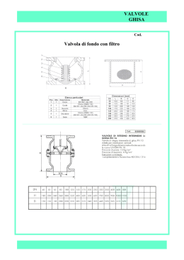
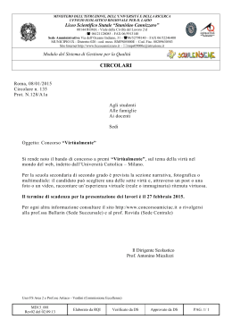
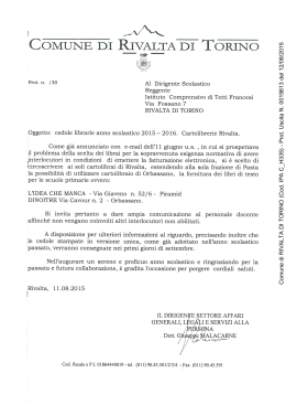
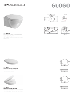
®
ELECTRIC COMBI WALL BOILER
FOR HEATING AND SANITARY HOT WATER PRODUCTION
INSTANTANEOUS WITH ACCUMULATION TANK
Combi. Elektra .. BP-L series
CALDAIA MURALE ELETTRICA
RISCALDAMENTO E PRODUZIONE DI ACQUA CALDA
SANITARIA ISTANTANEA CON BOLLITORE AD
ACCUMULO
Combinata serie Elektra .. BP-L
USE AND MAINTENANCE MANUAL
MANUALE D'USO E MANUTENZIONE
EQUIPMENT COMPLIANT CE DIRECTIVE 2006/42 - IEC 60335-2-21:2012 with IEC 60335-1:2010 with EN
60335-2-21:2003+A1:2005+A2:2008 - EN 60335-1:2012 - EN 62233:2008.
APPARECCHI CONFORMI CE ALLA DIRETTIVA EUROPEA 2006/42. Costruiti e conformi alle norme IEC
60335-2-21:2012 con IEC 60335-1:2010 con EN 60335-2-21:2003+A1:2005+A2:2008 - EN 60335-1:2012 EN 62233:2008.
ELECTRIC WALL BOILER
Series ELEKTRA. … BP-L
Presentation
Thank you for choosing an electric wall boiler FIAMMA, built with the most modern
technologies, safe and tough materials, so as to ensure maximum efficiency of use, total
quality of the device and extreme safety for the user.
The series Elektra .. is built according to European standards dir. machines 2006/42 - IEC
60335-2-21:2012 IEC 60335-1:2010 and EN 60335-2-21:2003 + A1 : 2005 + A2 : 2008 EN 60335-1:2012 - EN 62233:2008 .
The obtained results can be summarized in the following key points:
- Noiseless functioning, thanks to maximum insulation of the device by means of
innovative special materials that ensures minimum heat loss.
- High degree of reliability, thanks to a careful choice of materials and to sever tests
carried out during production for each unit built.
- High performance with maximum efficiency, thanks to a modulation of electrical power to
the heating elements, according to the actual need of energy by the system or the need of
sanitary water. The system D.E.S. manages the device with temperature probes
positioned in each sensitive point of the boiler, so as to manage both comfort and
economy functioning, in order to reduce power consumption when the device is not used
at the maximum capacity or demand.
- The appliance is fully adjustable both in water temperature of the heating system (with
the possibility to choice of system at high and low temperature for underfloor systems) and
in the domestic hot water temperature.
- The assembly of the components has been realized in order to allow an easy access to
them, all from the front of the unit, for ordinary and extraordinary maintenance.
We recommend you to follow our instructions, and we suggest to contact the area
authorized service FIAMMA in order to prepare a planned maintenance contract which can
ensure suitable operation at maximum efficiency and safety, so that your machine use can
go a long way.
In renewing our thanks, our technical department and our sales network, are at your
disposal for any further information
FIAMMA GIRO s.r.l.
Company group
The company FIAMMA GIRO s.r.l. declines all responsibility for possible inaccuracies contained in this pamphlet, if due to printing
errors or inadvertent errors. However, reserves the right to make changes to its products that it deems useful or necessary, without
affecting the essential characteristics of the products manufactured and marketed.
2
Dimensions
The series Elektra. .. BP-L has four power levels, but the same overall
dimensions:
Elektra.6 BP-L
6 kW maximum electrical output
Elektra.12 BP-L
12 kW maximum electrical output
Elektra.18 BP-L
18 kW maximum electrical output
Elektra.24 BP-L
24 kW maximum electrical output
L
L
P
L
H
Packaging dimension
Appliance dimension
L (Width) :
H (Height) :
P (Depth) :
Weight :
660
875
300
61
mm
mm
mm
kg
Width :
Height :
Depth :
Weight :
3
710
940
390
64,5
mm
mm
mm
kg
Hydraulic connections – Dimensional of connection arrangement.
Hydraulic connections
M
Heating delivery :
R
Heating return :
AF
Cold sanitary water inlet :
AC Hot sanitary water output:
VSR Heating safety valve (3 bar) :
VSS Sanitary safety valve (6 bar) :
RC Manual Filling tap (restoring water pressure)
¾”
¾”
½”
½”
½”
½”
M
M
M
M
F
F
Bottom view (under the boiler)
VSR
RC
AF
VSS
AC
M
R
Electrical
supply
200
65
220
165
120
80
95
300
4
Main technical features Elektra 6.. - Elektra 12..
Elektra.6 BP-L 6 kW maximum electrical output
Single-phase electrical supply 230 V - 50 Hz.
Weight : 60 kg.
Capacity of tank 37 lt. Glass-lined steel with inspection flange and magnesium
anode.
Electrical / heat power available at heating: 6 kW obtained by n°.1 resistance
group (n°.1 3x2 kW).
Electrical power at hot water tank resistance: 2 kW (2.000 W).
Maximum head available at the pump 5 m H 2 O
Expansion vessel capacity of 8 lt.
Safety valve of heating circuit: 3 bar.
Safety valve of sanitary circuit: 6 bar.
Maximum heating operating pressure: 2.5 bar.
Maximum sanitary operating pressure: 5.5 bar.
Minimum operating pressure in the heating circuit: 0.6 bar.
Minimum operating pressure in the sanitary, comfort system: 0.25 bar.
Minimum operating pressure in the sanitary, economy system: 0.05 bar.
Maximum limit of thermal safety heating circuit - boiler body: 100 °C.
Elektra.12 BP-L 12 kW maximum electrical output
Single-phase electrical supply 230 V - 50 Hz.
Weight : 61 kg.
Capacity of tank 37 lt. Glass-lined steel with inspection flange and magnesium
anode.
Electrical / heat power available at heating: 12 kW obtained by n°.2 resistance
groups (n°.2 3x2 kW).
Electrical power at hot water tank resistance: 2 kW (2.000 W).
Maximum head available to the pump 5 m H 2 O
Expansion vessel capacity of 10 lt.
Safety valve of heating circuit: 3 bar.
Safety valve of sanitary circuit: 6 bar.
Maximum heating operating pressure: 2.5 bar.
Maximum sanitary operating pressure: 5.5 bar.
Minimum operating pressure in the heating circuit: 0.6 bar.
Minimum operating pressure in the sanitary, comfort system: 0.25 bar.
Minimum operating pressure in the sanitary, economy system: 0.05 bar.
Maximum limit of thermal safety heating circuit - boiler body: 100 °C.
5
Main technical features of Elektra 18.. – Elektra 24..
Elektra.18 BP-L 18 kW maximum electrical output
Single-phase electrical supply 230 V - 50 Hz.
Weight : 62 kg.
Capacity of tank 37 lt. Glass-lined steel with inspection flange and magnesium
anode.
Electrical / heat power available at heating: 18 kW obtained by n°.3 resistance
groups (n°.3 3x2 kW).
Electrical power at hot water tank resistance: 2 kW (2.000 W).
Maximum head available at the pump 5 m H 2 O
Expansion vessel capacity of 10 lt.
Safety valve of heating circuit: 3 bar.
Circuit safety valve of sanitary circuit: 6 bar.
Maximum heating operating pressure: 2.5 bar.
Maximum sanitary operating pressure: 5.5 bar.
Minimum operating pressure in the heating circuit: 0.6 bar.
Minimum operating pressure in the sanitary, comfort system: 0.25 bar.
Minimum operating pressure in the sanitary, economy system: 0.05 bar.
Maximum limit of thermal safety heating circuit - boiler body: 100 °C.
Elektra.24 BP-L 24 kW maximum electrical output
Single-phase electrical supply 230 V - 50 Hz.
Weight : 63 kg.
Capacity of tank 37 lt. Glass-lined steel with inspection flange and magnesium
anode.
Electrical / heat power available at heating: 24 kW obtained by n°.4 resistance
groups (n°.4 3x2 kW).
Electrical power at hot water tank resistance: 2 kW (2.000 W).
Maximum head available to the pump 6 m H 2 O .
Expansion vessel capacity of 10 lt.
Safety valve of heating circuit: 3 bar.
Safety valve of sanitary circuit: 6 bar.
Maximum heating operating pressure: 2.5 bar.
Maximum sanitary operating pressure: 5.5 bar.
Minimum operating pressure in the heating circuit: 0.6 bar.
Minimum operating pressure in the sanitary, comfort system: 0.25 bar.
Minimum operating pressure in the sanitary, economy system: 0.05 bar.
Maximum limit of thermal safety heating circuit - boiler body: 100 °C.
6
Switching-on the boiler
CONTROL PANEL
General
switch
Display
Idrometro
hydrometer
Idrometro
The control panel is composed of : display, function selection keys, general
switch and the hydrometer it is placed in the lower left corner
in front of the unit (see image above).
Using analogical hydrometer.
The analogical hydrometer control panel has a dial with unit of measure in a
bar, from 0 to 6 bar. The water pressure in the heating system is indicated by
the index of the black arrow.
The optimum pressure for the system is between 1 and 1.5 bar.
More than 1.5 bar you can have a maximum pressure of 2 bar (maximum
expansion of the system during the rise in temperature). More than 2 bar
pressure the system is not in the range of operation, and mechanical safety
valve (preset to 3 bar) can start to lose water.
The minimum operating pressure is 0.8 bar (+/- 0.2 bar). The differential
positive or negative tolerance is due to the operation of the water pressure
switch with fixed setting.
7
KEYBOARD PANEL (Control panel)
J7
J6
J2
J3 J4
J5
MEANING OF THE KEYS IN USER MODE
KEY
FUNCTION
J5
Display / Tank setpoint decrease (only if JP8 = 0)
J6
Display / Tank setpoint increase (only if JP8 = 0)
J7
ON - OFF Switching
Display temperature output / Display setpoint output
Unlock error of safety thermostat
J4
Summer – Winter switching
J2
Display / Increase of heating setpoint (or room temperature)
J3
Display / Decrease of heating setpoint (or room temperature)
J5 + J6
Enabling function Eco/Comfort (only if JP8 = 0)
TURNING ON THE BOILER
The boiler is switched-on by means of the light General switch located on the
left of the display in the instrument panel of the boiler. Pressing the switch
upward to the ON position, it will light in the presence of single-phase supply
(230V-50 Hz). Then, it shall be pressed the ON-OFF (J7) on the keypad to
switch the power from stand-by to the operating position; the display will light
up of blue and will appear various symbols signaling function /faults etc.
At this point it shall be chosen the mode of operation, summer or winter
operation.
8
CHOICE OF THE OPERATION MODE (winter/summer)
Pressing the key MODE (J4), it will be chosen the mode of operation, wintry or
summery.
Pressing repeatedly each time for at least 5 seconds, you switch from WINTER
to SUMMER or from SUMMER to WINTER then.
When the device will be in WINTER mode, on the display will appear the
symbol C (snow).
When the device will be in SUMMER mode, on the display will appear the
symbol B (sun).
TEMPERATURE VARIATION OF THE HEATING CIRCUIT
When the apparatus has been set with the snow symbol ( C) for the wintry
functioning, you can change the maximum temperature of heating circuit
pressing one of the two keys with the radiator symbol located on the left of the
display (J2 and J3 keys).
The key with the symbol I+ (J2), increases the temperature, and
the key with the symbol I - (J3), decreases the temperature.
TEMPERATURE VARIATION OF HOT SANITARY WATER
The temperature of hot sanitary water can be varied independently from the
mode of functioning, both wintry and summery.
The two keys with the Tap symbol on the left of the control panel,are used to
set the maximum temperature of the hot sanitary water circuit.
The key with symbol H + (J6) increases the temperature, and the one with
the symbol H - (J5) decreases the temperature.
ON-OFF KEY
Display Simbols
The ON/OFF key (J7), in addition to put the
boiler in stand-by mode, allows to reset
(unlock) the apparatus in case of high
temperature lock.
If the lock would be caused by lack of water
9
pressure alarm, the recovery will be automatic after that the hydric pressure will be
restored at the minimum operating level (0,8 bar) by means of the opening and the closure
of the charging tap placed under the boiler (black handle).
The display has several symbols, signaling in addition to operation modes, also the
various alarm or system displays:
SYMBOL
L
J
I
H
G
F
E
C
B
A
Level of
modulation
MEANING
Malfunction
Request of burner switch-on
Heating request
Tank enabled
Function sanitary Comfort activated
Parameter menu activated
Anti-freeze request activated
Winter mode
Summer mode
OFF mode
Indicates the instantaneous power of the boiler from 0 to 100%
10
INSTALLATION
TECHNICAL NOTE FOR INSTALLER AND TECHNICAL MAINTENANCE
HYDRAULIC SCHEME
(Elektra 12 BP-L 014 version)
Legend
- TS Safety thermostat.
- VSS Safety valve for sanitary circuit 1/2”x6 bar.
- SP Brazed heat exchangers.
-S
Thermowell for immersion sensor.
-R
Hydraulic connection in-let heating circuit.
- AC Hydraulic connection out-let sanitary hot-water.
-M
Hydraulic connection out-let heating circuit.
- RS Sanitary Resistance of 2 kW.
- VE Expansion vessel heating circuit.
- VSR Safety valve heating circuit 1/2”x3 bar
- AF Hydraulic connection in-let sanitary cold-water.
- rs
- PA
- CC
- VDP
- RC
- rsc
- BS
- AM
- rsb
Filling tap.
Water pressure switch.
Boiler body.
Pressostatic Diverter valve.
Boiler resistance of 6 kW.
Drain valve of boiler body.
Hot water storage tank of 37 lt.
Magnesium anode.
Drain valve of tank.
For the other models, the only changes refer to the number of electric resistances; the 6 kW
version has only one 6 kW resistance (detail RC), the 12 kW version has two 6 kW resistances, the
18 kW version has three 6 kW resistances and the 24 kW version has four 6 kW resistances.
11
CONNECTING SCHEME
F
N
1
2
4
3
5
6
7
brown
blu e
blue
brown
PI
8
9
10
11
J1 1
1
J5
black
7
Yellow/green
56
white
6
55
yellow
5
G3
G2
G1
4
brown
3
red
2
blue
1
TA
G5
G4
N
black
brown
54
black
3
2
1
J1 1
J6
Inte rfac cia 961
R S485
Opentherm
0
1
SM SB SE
cTS
MS
12
J12
blue
brown
blue
brown
brown
blue
brown
b lu e
red
red
J14
brown
43 42 41 40 3 9 38 37 36
brown
JP7
J P8
JP10
JP9
51 51 50 49 48 47 46 45 44
PSA
FT
F
brown
N
blue
b lack
black
b lack
blue
23 0V-50 Hz.
MAIN ELECTRIC SCHEME
ON/OFF
blue
TS
blu e
GX
brown
Conta ctors
blue
R
BF..
A1
A2
blue
Main PCB
GX
b
N
brown
b
Contatto
TS
black
black
b
black
b
FT
brown
b rown
Legend electric scheme
Single phase
F
Neutral
N
Selected Phase from Contactor
FT
Electric Pump
PI
Control of contact TS on Contactor of power (C-NO)
cTS
Sanitary Microswitch (control Comfort function)
MS
Control gate triac n°1 (4KW power)
G1
Control gate triac n°2 (2KW power)
G2
Control gate triac n°3 (4KW power)
G3
Control gate triac n°4 (2KW power)
G4
Control gate triac n°5 (2KW Sanitary tank)
G5
Delivery heating probe (ntc sensor)
SM
Sanitary tank probe (ntc sensor)
SB
External probe (sensor)
SE
Water pressure switch
PSA
Safety thermostat
TS
Room thermostat (terminal provided)
TA
13
L
TRIAC – Connection scheme
14
MANUFACTURE CONSTANTS
FUNCTION
Value
DELTA OFF TANK PROBE
0°C
DELTA ON TANK PROBE
-1°C
INTERVENTION TEMPERATURE ANTI LEGIONELLA
65°C
INTERVENTION INTERVAL ANTI LEGIONELLA
7 Days
MAX TEMPERATURE PRIMARY
80°C
TIME OF PUMP FUNCTIONING IN ANTI-LOCK
10 sec
INTERVENTION TIME ANTI-LOCK PUMP
24H
TEMPERATURE ANTIFREEZE ON (only circulator)
7°C
TEMPERATURE ANTIFREEZE ON (heat exchanger ignition)
4°C
TEMPERATURE ANTIFREEZE OFF
20°C
SETPOINT AND PARAMETERS
FUNCTION
Default RANGE
HEATING SETPOINT
60°C
30 – 75 °C
FLOOR HEATING SETPOINT
30°C
10 – 40 °C
ROOM SETPOINT (with external probe present)
20°C
10 – 30 °C
TANK SETPOINT
60°C
30 – 65 °C
INSTANTANEOUS DHW SETPOINT
50°C
30 – 60 °C
PARAMETERS
FUNCTION
N°
Def.
RANGE
EXTERNAL PROBE START UP
1
0
BUILDING COEFFICIENT OF DISPERSION
2
35
5 – 35 °C
SANITARY POST CIRCULATION
3
15
1 – 180 sec
HEATING POST CIRCULATION
4
30
1 – 180 sec
IGNITION DELAY EXCHANGER HEATING
5
0
0 – 240 sec
MIN. IGNITION TEMP. CIRCULATOR
6
30
0 – 50 °C
DELIVERY DIFFERENTIAL OF TANK
7
15
0 – 20 °C
0–1
TEMPERATURES
FUNCTION
N°
DELIVERY TEMPERATURE
t: “Ch”
TANK TEMPERATURE
t: “Dh”
EXTERNAL TEMPERATURE
t: “Ep”
OFFSET SETPOINT OF EXTERNAL PROBE
t: “Se”
SELECTION JUMPERS enable
Jumper
0/1
JP7
High temperature / Low temperature plant
JP8
Combined / Heating only
JP9
Sanitary with tank / Sanitary instantaneous
15
CONTROL OF MAIN HEAT EXCHANGER
According to the required power during the heat request, the controls G1-G4 related to the
main exchanger are turned on all or partially.
The actuation of each control is reduced to a lapse of 4 seconds. Higher is the required
power, more the control will remain operative in this lapse.
The power in heating or during a sanitary request is calculated by PID algorithm.
Please see in the pictures below two examples related to 40% and 60% of total power.
G4
G4
G3
G3
G2
G2
G1
G1
4s
4s
In case of simultaneous request of heating and tank, the controls G1-G4 related to the
main heat exchanger will be directed in the following way:
Boiler status
Only heating request
Primary G1-G4
Tank G5
G1 – G4 =
G5 = OFF
modulation
G1–G3 = modulation G5 = ON
G4 = OFF
Heating request + Tank request
Heating request + Flow switch request
G1–G3 = modulation G5 = ON
G4 = OFF
Controls rotation:
Every hour the order of ignition of triac G1-G4 controls is rotated in such a way to partition
evenly in time the use of all heating elements.
16
CONTROL OF EXERNAL PROBE
Installation and functioning at sliding temperature
For the connection of the external probe, it shall be used the
Original Kit FIAMMA code F.532 provided in the accessories of the
electric boilers Elektra.
The electrical connection shall be done in the external terminal at
the general electric panel already prearranged in the standard
cabling of the boiler. The connection must be carried out with
junction cables and wires having a minimum section of 1,5 mm and,
if possible, avoiding the insertion along with electric lines, digital
lines of inverter or other not compatible.
After the connection the external probe must be enabled by means of the introduction of a
variation of N°1 parameter, changed from 0 to 1.
Then the setpoint chased by the heating delivery probe will be calculated as follows:
Ti = [ (Troom – T e) * K e / 10 ] + Troom
Ti
3,5
3,0
2,5
2,0
1,5
80
70
1,0
60
0,8
50
0,5
40
30
20
20
15
10
5
0
-5
-10
-15
-20
Te
Example of calculation for several values of Ke
The coefficient Ke is the leakage of the building and it can be set by N°2 parameter.
Te, is the temperature measured by the external probe.
Troom is the setpoint related to the desired room temperature.
17
ANTIFREEZE FUNCTION
In case the delivery probe measures a temperature lower than 7°C, the circulator is
activated.
If the temperature goes down the value of 4°C the m ain heat exchanger is ignited until the
delivery temperature has reached 20°C. The antifree ze function is active also with the
boiler turned OFF (function in standby mode but with bright switch on).
TANK REQUEST (Jumper JP9 = 0)
Standby or with simultaneous heating request: in this case if the temperature measured
by the tank probe is lower than the tank setpoint - 1°C, is activated the control G5 related
to the tank resistance.
When the temperature measured by the probe tank is higher than the tank setpoint, the
control G5 is disconnected.
Sanitary flow switch request: when a request gets by the sanitary flow switch, the control
G5 related to the tank resistance is activated independently by the temperature.
In ECO Mode is not activated any resistance of the primary heat exchanger.
In the COMFORT mode simultaneously are also checked the controls G1, G2. G3, G4 relative
to the primary heat exchanger bringing the flow temperature to the setpoint value tank plus a
differential set with parameter N°7.
At the end of the request the pump is fueled for a time equal to the value set by parameter N°3.
Pre-heat exchanger primary: when COMFORT is activated in standby condition the primary heat
exchanger temperature is maintained in order to ensure a prompt response of the sanitary sector.
The primary heat exchanger is maintained at a temperature equal to the Setpoint plus a tank
temperature difference can be set by parameter N°7.
ANTILEGIONELLA FUNCTION
The system checks continuously the tank temperature.
If within a certain time lapse the temperature does not reach 65°C, the tank resistance is
automatically ignited in order to avoid bacterium growth.
The time of intervention of legionella function is 3 hours by the first ignition and then every
7 days.
DHW DEMAND INSTANTANEOUS
When receiving a request by the microswitch sanitary, the circulator is powered and controlled
commands are G1, G2, G3, G4 relative to the primary heat exchanger leading the delivery
temperature to the setpoint value sanitary + a differential be set with parameter N°7.
At the end of the request the pump remains powered for a time equal to the value set by
parameter N°3.
18
HEATING REQUEST
As the contact of room thermostat closes, if the mainboard is in winter mode, the system
pump is only activated if the temperature of the primary heat exchanger is higher than the
temperature set by parameter N°6.
If the value of temperature measured by the primary heat exchanger probe is lower than the
programmed delivery setpoint, the triac are ignited in sequence as per the required power.
This occurs only after a settable time by parameter N°5.
The instant power of the boiler and the related control of triac G1-G4 takes place by
means of PID regulator.
At the end of the request the pump remains supplied for a time equal to the value programmed
by N°4 parameter.
MEANING OF THE KEYS OF TEMPERATURE MENU
To log in temperature menu, press simultaneously J3 and J5 keys. The symbol
appear on the display.
KEY
FUNCTION
J7
Exit by temperature menu
J2
Temperature index increase
J3
Temperature index decrease
F will
MEANING OF KEYS OF PARAMETERS MENU
To log in parameters menu, press simultaneously the keys J2 and J6 for 4 seconds.
The symbol F will appear on the display.
KEY
FUNCTION
J5
Parameter value decrease
J6
Parameter value increase
J7
Exit by parameters menu
J2
Parameter index increase
J3
Parameter index decrease
19
“Heating elements status”
The dashes located in the upper part indicate the heating elements status. Each dash
corresponds to a 2 kW element. The first 6 dashes refer to heating modules of primary
heat exchanger. The dash on the right upper corner refers to the heating module
dedicated to the tank (only if JP8=0 and JP9=0)..
G1
G2
G3
G4
G5
“Heating request”
When an heating request occurs, the temperature measured by the delivery probe is
displayed and the symbol I starts to flash. On the small digit is displayed the tank
temperature. The instantaneous power of the boiler is indicated by the level of modulation.
In any moment it is possible to observe which triac are turned on.
In the case of boiler with heating only (JP8 = 1) is only displayed the temperature
of the primary heat exchanger:
“Flow switch request (comfort function)” (only if JP8=0)
When a flow switch request occurs, the temperature measured by the delivery probe is
displayed and the symbol H starts to flash. On the small digit is displayed the tank
temperature. The instantaneous power of the boiler is indicated by the level of modulation.
In any moment it is possible to observe which triac are turned on.
20
“Temperature display”
On the small digit will appear the writing t : followed by the description of the selected
temperature, while the big digit will show the temperature value.
FUNCTION
N°
DELIVERY TEMPERATURE
t: “Ch”
TANK TEMPERATURE
t: “Dh”
EXTERNAL TEMPERATURE
t: “Ep”
EXTERNAL PROBE OFFSET SETPOINT
t: “Se”
“Parameters display”
On the small digit will appear the writing P : followed by the index of the selected
parameter, while the big digit will show the parameter value.
MALFUNCTIONING CODE
When a malfunction occurs, the writing “Err F X” appears, where X indicates the related
error code
CODE “Err”
MEANING
9
Hardware eeprom failure
1
Insufficient system water pressure
4
Err tank probe / instant sanitary - only if JP8 = 0
3
Err boiler delivery probe
8
Safety thermostat block
21
FUNCTIONING WITH REMOTE CONTROL ENCRONO OT1, OT2 or OT11
LOOK OF THE REMOTE CONTROL ENCRONO OT1, OT2 and KRONOS OT11
Elektra … BP-L, can be connected
by means of its card and an
additional module to install on a
prearranged part, to a compatible
remote control device Opentherm®,
like Encrono OT1 or OT2 or OT11.
This can be obtained by means of
the interface card (additional
module).
When the card finds the connection
with the remote control, on the LCD
display appears the symbol M.
The compatible remote control
OpenTherm becomes the master of
the entire system, therefore almost
all the functionalities, as the setting of heating and hot sanitary water setpoint or the
control of system status, are directly executable by it, in relation with the kind of application
on which the card is used.
By means of the remote control it is possible to restore the system from the non-volatile
lock status.
The communication between the remote control and the electronic card fitted with D.E.S.
system can be interrupted in the following ways:
- Interruption of the connection between remote control and card:
In this case, after 1 minute, the card starts to work in local mode.
- Noise on communication cable between remote control and card:
In this case it is possible that remote control and card do not manage to communicate
(wrong data interpretation), therefore, after a certain lapse appears the related error signal.
If the noise on the communication cable ends, the dialog between remote control and the
card is automatically restored and the malfunction disappears.
TRANSPARENT PARAMETERS
This function is available only with the use of remote control OT2 or OT11. The digital
electronic PCB is equipped with 5 parameters adjustable by the installer, in order to set the
functioning of the system in conformity to the final application. The parameters have the
same meaning of the ones described in the table “parameters”.
22
Parameters Table
FUNCTION
EXTERNAL PROBE ENABLING
BUILDING LEAKAGE COEFFICIENT
SANITARY POST CIRCULATION
HEATING POST CIRCULATION
HEATING EXCHANGER CIRCUL. START
MIN. IGNITION TEMPER. CIRCULATOR
DELIVERY DIFFERENTIAL OF SANITARY
N°
1
2
3
4
5
6
7
def.
0
35
15
30
0
30
15
RANGE
0–1
5 – 35 °C
1 – 180 sec
1 – 180 sec
0 – 240 sec
0 – 50 °C
0 – 20 °C
RANGE OF SETPOINT ADJUSTABLE BY MEANS OF REMOTE CONTROL
Interval of temperature setting with high temperature system
(JP7 = 0)
Interval of temperature setting with low temperature system
(JP7 = 1)
Interval of tank temperature setting
30 °C ÷ 75 °C - step 1°C
Pre-set value: 60 °C
15 °C ÷ 40 °C - step 1°C
Pre-set value: 30 °C
30 °C ÷ 65°C - step 1°C
Pre-set value: 60 °C
FUNCTIONING OF BOILER ELEKTRA WITH REMOTE CONTROL
The actuation of heating mode takes place after an heating request from remote control
(value of heating setpoint calculated by remote control higher than heating setpoint set by
the user on remote control divided by two) and in the winter mode status.
It also enabled the relay which controls the valve opening area managed by Enchrono/Kronos.
HOT SANITARY WATER MODE (if only JP8 = 0)
The electric card of Elektra operates in the same way described previously. The desired setpoint
is set by the user on the remote control.
Through the Enchrono OT1/OT2 you can enable the ECO/COMFORT by pressing P. When
the ECO function is active, the temperature of sanitary and the symbol H is the alternating
temperature. In the COMFORT mode, the temperature of the hot water circuit appears fixed
only when there is a request by the micro sanitary.
CONTROL PANEL IN USER MODE
The pressure of one key/two keys activates the backlighting of LCD display.
KEY
J5
J6
J7
FUNCTION
Disabled in Opentherm mode
Disabled in Opentherm mode
Unlock error of safety thermostat
J4
Disabled in Opentherm mode
J2
Disabled in Opentherm mode
J3
Disabled in Opentherm mode
J5 + J6
Enabling of Eco/Comfort function
23
CONTROL PANEL IN INSTALLER MODE
The keys have the same functioning described on par. “Control panel in user mode”.
DISPLAY OF MALFUNCTIONS
CODE “Err”
F 009
MEANING
Hardware eeprom fault
F 001
F 004
Insufficient water pressure in the system
Tank probe error / instant sanitary - only if JP8 = 0
F 003
Boiler delivery probe error
F 008
Safety thermostat lock
For further details related to remote controls series OT1 / OT2 / OT11, please see the
related technical specifications.
24
SPARE PARTS
21
1
22
2
3
23
4
5
24
6
25
7
26
8
27
9
28
10
11
29
12
30
13
31
14
15
16
17
18
32
19
33
20
4
Particular
Particular : Boiler body / resistances
34
35
20
46
16
25
37
25
38
Upper particular / resistance
Front unit
36
37
40
39
7
41
25
7
26
10
8
42
7
43
9
45
12
13
44
Particular : Flange/probe/resistance/anode group Sanitary tank.
46
47
46
The flange/tank group, included in one vitrified
piece, sheath probe, resistance probe, and
inspection and support flange.
The substitution of the anode magnesium,
involves the disassembly of the group.
The substitution of the electrical resistance does
not involve the emptying of the sanitary tank
because inside the vitrified steel probe.
48
46
49
26
Spare parts - Legend
1
2
3
4
5
6
7
8
9
10
11
12
13
14
15
16
17
18
19
20
21
22
23
24
25
26
27
28
29
30
31
32
33
34
35
36
37
Upper closing fairing of Elektra .. B/BP-L. ………………...………. Cod.P.2025
Tetrapolar Terminal block for Elektra 6/12/18 … . …………..………...Cod.P.2054
Tetrapolar Terminal block for Elektra 24 … . ………………..………...
Terminal of the electric supply line 230V (Ph). …………..…............ Cod.P.2073
Terminal of the electric supply line 230V (blue - N). …................... Cod.P.2072
Terminal line of electrical ground (green/yellow)…………………..... Cod.P.2074
General electric box (panel circuit board / contactor).
Flat cable connection LCD display. ……..………….......................... Cod.P.2095
Left side panel of casing. ……..……………...................................... Cod.P.2030
Triac of electric power (40A-600V). ……………................................. Cod.P.2293
Return tube heat exchanger-pump. ………………........................... Cod.P.2044
5 way diverter valve. ………….………….......................................... Cod.P.916
Plate heat exchanger for Elektra C/BP 6 kW version. ………..…..... Cod.P.2138
Plate heat exchanger for Elektra C/BP 12 kW version.. ………....... Cod.P.9098
Plate heat exchanger for Elektra C/BP 18 kW version.. ……........... Cod.P.2139
Plate heat exchanger for Elektra C/BP 24 kW version.. ………….... Cod.P.2143
Expansion vessel 8 lt. C/BP 6 kW version. …………………........... Cod.P.289
Expansion vessel 10 lt. C/BP 12/18/24 kW version. ………........... Cod.P.1846
Diverter valve-heat exchanger tube. ………..………........................ Cod.P.2041
Water pressure switch (minimum pressure). ………………..............Cod.P.1082
Return pump-boiler body tube. ……………………........................... Cod.P.2037
Circulator at variable prevalence (electric pump). …….................... Cod.P.1979
Flexible tube for expansion vessel. ……………………...….............. Cod.P.1531
Hydrometer. ………………............................................................... Cod.P.146
Heating Safety valve - 3 bar.. ………………….………..................... Cod.P.178
Outlet tube for filling tap water. …………………………………........ Cod.P.2043
Filling tap water ¼”-¼”. ……………………………………................ Cod.P.6605
Right side panel of casing. ……………………….……….………….. Cod.P.2029
Sanitary tank for Elektra .. B/BP.. . …………………...…………….... Cod.P.1999
Elektra .. BP-L. electrical wiring. ……..……………........................... Cod.P.2064
Outlet tube heat exchanger- diverter valve. ……………................... Cod.P.2045
Body boiler Elektra 6 N/C/B/BP-L. ………………….......................... Cod.P.2110
Body boiler Elektra 12 N/C/B/BP-L. …………………........................ Cod.P.1995
Body boiler Elektra 18 N/C/B/BP-L. …………………….................... Cod.P.1996
Body boiler Elektra 24 N/C/B/BP-L. ………………….…….…........... Cod.P.2123
Outlet heating tube diverter valve-body boiler. …………..……......... Cod.P.2039
Inlet tube cold water-diverter valve. ……...…………………….......... Cod.P.2046
Outlet heating tube (diverter valve-dima). ....................................... Cod.P.2040
Inlet tube tank water (outlet exchanger-tank)…………………..….... Cod.P.2038
Sanitary safety valve 6 bar. ………..………………........................... Cod.P.180
Outlet tube hot water tank (tank-dima). …………………………….... Cod.P.2036
Lower panel (lower grid). ………...………..……………..………….... Cod.P.2024
Inlet tube filling tap. ……………………………….............................. Cod.P.1826
PCB of operating (Elektra N/C/B/BP.. ). ……………………………... Cod.P.2057
Contactor of power for Elektra 6 .. . ………………………………...... Cod.P.2103
Contactor of power for Elektra 12 .. . ………….…………………...... Cod.P.2067
Contactor of power for Elektra 18 .. ………………………………...... Cod.P.2104
Contactor of power for Elektra Elektra 24 .. . …………....…...…...... Cod.P.2101
O-Ring gasket for 3x2 kW electrical resistance for Elektra 6÷24. …..Cod.P.2078
Electrical resistance. 3x2 kW for Elektra 6÷24 .. . …..……………….. Cod.P.1998
27
38
39
40
41
42
43
44
45
46
47
48
49
Drain tap ¼” for Elektra .. boiler/tank. ………………………....…….. Cod.P.2190
Contact safety thermostat 100°C. Elektra .. . …………….……….. Cod.P.1195
Automatic bleed valve (Jolly). ……………...…………...................... Cod.P.174
Front panel Elektra .. B/BP-L . …………..……………...................... Cod.P.2031
Display Lcd (Lcd pcb). ……..………………...................................... Cod.P.1763
Instrument panel of Elektra (profil+lexan keyboard P.2099). ………....... Cod.P.2164
Lighting general switch (On-Off switch). …………………................. Cod.P.1099
Sanitary microswitch. ……………………….…….............................. Cod.P.561
Flange/sheath probe support/sheath group for sanitary resistance. Cod.P.2163
Magnesium anode Elektra .. B/BP-L. …………………..................... Cod.P.2165
Gasket flange Elektra .. B/BL.. tank. …………….............................. Cod.P.2166
Ceramic electric resistance 2 kW for sanitary tank. ......................... Cod.P.2167
28
CALDAIA MURALE ELETTRICA
Serie ELEKTRA. … BP-L
Presentazione
Vi ringraziamo per aver scelto una caldaia murale elettrica FIAMMA, costruita con le più
moderne tecnologie termotecniche, materiali robusti e sicuri, tali da garantire il massimo di
efficienza per l'uso, la qualità totale per l'apparecchio ed una estrema sicurezza per
l’utente.
La serie Elektra.. è costruita secondo le norme europee dir. macchine 2006/42 - IEC
60335-2-21:2012 con IEC 60335-1:2010 con EN 60335-2-21:2003+A1:2005+A2:2008 EN 60335-1:2012 - EN 62233:2008.
I risultati ottenuti si possono riassumere in alcuni punti qualificanti per il prodotto:
- funzionamento particolarmente silenzioso con coibentazione massima dell’apparecchio
tramite materiali speciali innovativi che garantisce minima dispersione del calore.
- grado di affidabilità elevato dovuto all'accurata scelta dei materiali ed ai rigorosi collaudi
in produzione per ogni apparecchio costruito.
- elevato rendimento, con efficienza massima grazie ad una modulazione di potenza
elettrica alle resistenze in base all’effettivo bisogno di energia da parte dell’impianto o del
fabbisogno di produzione sanitaria. Il sistema D.E.S. gestisce l’apparecchio tramite sonde
di rilevamento temperatura posizionate in ogni punto sensibile della caldaia, ottenendo di
gestire sia il funzionamento confort oppure economy a propria scelta per ridurre i consumi
quando l’apparecchio non è utilizzato a massima potenza o richiesta.
- l’apparecchio è totalmente regolabile sia nella temperatura dell’acqua dell’impianto di
riscaldamento (con possibilità di scelta di impianto ad alta che bassa temperatura per
impianti a pavimento radiante, sia nella temperatura dell’acqua calda sanitaria.
- L'unione dei componenti è stata realizzata in modo da permettere un facile accesso ad
essi, tutto dalla parte frontale dell’apparecchio, sia per la manutenzione ordinaria che per
la manutenzione straordinaria.
Vi raccomandiamo di seguire attentamente i nostri consigli, suggerendoVi di contattare il
servizio di assistenza autorizzato FIAMMA di zona per predisporre un contratto di
manutenzione programmata che garantisca il funzionamento idoneo al massimo
dell’efficienza e della sicurezza, affinché il Vs. apparecchio possa durare a lungo. Nel
rinnovarVi i nostri ringraziamenti, i nostri uffici tecnici e la nostra rete tecnico-commerciale
sono a Vostra disposizione per ogni ulteriore informazione e/o ragguaglio tecnicoinformativo.
FIAMMA GIRO s.r.l.
Company group
La ditta FIAMMA GIRO s.r.l. declina ogni responsabilità per le possibili inesattezze contenute nel presente opuscolo, se dovute ad
errori di stampa o di trascrizione. Si riserva comunque il diritto di apportare ai propri prodotti quelle modifiche che riterrà utili o
necessarie, senza pregiudicare le caratteristiche essenziali dei prodotti costruiti e commercializzati.
29
Dimensioni d’ingombro
La serie Elektra. .. BP-L si sviluppa su quattro livelli di potenza, ma stesse
dimensioni d’ingombro :
Elektra.6 BP-L
6 kW di potenza elettrica massima
Elektra.12 BP-L
12 kW di potenza elettrica massima
Elektra.18 BP-L
18 kW di potenza elettrica massima
Elektra.24 BP-L
24 kW di potenza elettrica massima
L
L
P
L
H
Dimensioni d’ingombro imballo
Apparecchio
L (Larghezza) :
H (Altezza) :
P (Profondità) :
Peso :
660
875
300
61
mm
mm
mm
kg
Larghezza :
Altezza :
Profondità :
Peso :
30
710
940
390
64,5
mm
mm
mm
kg
Attacchi Idraulici – Dimensionale di predisposizione attacchi.
Attacchi idraulici
M
Mandata Riscaldamento :
¾”
M
R
Ritorno Riscaldamento :
¾”
M
AF
Ingresso Acqua Fredda sanitaria :
½”
M
AC Uscita Acqua Calda sanitaria :
½”
M
VSR Valvola sicurezza riscaldamento (3 bar) :
½”
F
VSS Valvola sicurezza sanitario (6 bar) :
½”
F
RC Rubinetto di carico manuale (ripristino pressione idrica)
Vista dal basso (sotto caldaia)
VSR
RC
AF
VSS
AC
M
R
Alimentazione
elettrica
200
65
220
165
220
120
80
95
300
31
Caratteristiche tecniche principali Elektra 6.. – Elektra 12..
Elektra.6 BP-L 6 kW di potenza elettrica massima
Alimentazione elettrica monofase 230 V - 50 Hz.
Peso : 60 kg.
Capacità del Bollitore ad accumulo di 37 lt. In acciaio vetrificato con flangia di
ispezione ed anodo al magnesio.
Potenza elettrica/termica disponibile al riscaldamento di 6 kW ottenuta da n°.1
gruppo resistenza (n°.1 da 3x2 kW).
Potenza elettrica resistenza al serbatoio sanitario di 2 kW (2.000 W).
Prevalenza massima disponibile al circolatore di 5 m.c.a.
Capacità vaso espansione di 8 lt.
Valvola di sicurezza circuito riscaldamento da 3 bar.
Valvola di sicurezza circuito sanitario da 6 bar.
Pressione massima di esercizio riscaldamento 2,5 bar.
Pressione massima di esercizio sanitario 5,5 bar.
Pressione minima di funzionamento circuito riscaldamento 0,6 bar.
Pressione minima di funzionamento sanitario in sistema comfort : 0,25 bar.
Pressione minima di funzionamento sanitario in sistema economy : 0,05 bar.
Limite max di sicurezza termica circuito riscaldamento-corpo caldaia : 100°C.
Elektra.12 BP-L 12 kW di potenza elettrica massima
Alimentazione elettrica monofase 230 V - 50 Hz.
Peso : 61 kg.
Capacità del Bollitore ad accumulo di 37 lt. In acciaio vetrificato con flangia di
ispezione ed anodo al magnesio.
Potenza elettrica/termica disponibile al riscaldamento di 12 kW ottenuta da n°.2
gruppo resistenza (n°.2 da 3x2 kW).
Potenza elettrica resistenza al serbatoio sanitario di 2 kW (2.000 W).
Prevalenza massima disponibile al circolatore di 5 m.c.a.
Capacità vaso espansione di 10 lt.
Valvola di sicurezza circuito riscaldamento da 3 bar.
Valvola di sicurezza circuito sanitario da 6 bar.
Pressione massima di esercizio riscaldamento 2,5 bar.
Pressione massima di esercizio sanitario 5,5 bar.
Pressione minima di funzionamento circuito riscaldamento 0,6 bar.
Pressione minima di funzionamento sanitario in sistema comfort : 0,25 bar.
Pressione minima di funzionamento sanitario in sistema economy : 0,05 bar.
Limite max di sicurezza termica circuito riscaldamento-corpo caldaia : 100°C.
32
Caratteristiche tecniche principali Elektra 18.. – Elektra 24..
Elektra.18 BP-L 18 kW di potenza elettrica massima
Alimentazione elettrica monofase 230 V - 50 Hz.
Peso : 62 kg.
Capacità del Bollitore ad accumulo di 37 lt. In acciaio vetrificato con flangia di
ispezione ed anodo al magnesio.
Potenza elettrica/termica disponibile al riscaldamento di 18 kW ottenuta da n°.3
gruppo resistenza (n°.3 da 3x2 kW).
Potenza elettrica resistenza al serbatoio sanitario di 2 kW (2.000 W).
Prevalenza massima disponibile al circolatore di 5 m.c.a.
Capacità vaso espansione di 10 lt.
Valvola di sicurezza circuito riscaldamento da 3 bar.
Valvola di sicurezza circuito sanitario da 6 bar.
Pressione massima di esercizio riscaldamento 2,5 bar.
Pressione massima di esercizio sanitario 5,5 bar.
Pressione minima di funzionamento circuito riscaldamento 0,6 bar.
Pressione minima di funzionamento sanitario in sistema comfort : 0,25 bar.
Pressione minima di funzionamento sanitario in sistema economy : 0,05 bar.
Limite max di sicurezza termica circuito riscaldamento-corpo caldaia : 100°C.
Elektra.24 BP-L 24 kW di potenza elettrica massima
Alimentazione elettrica monofase 230 V - 50 Hz.
Peso : 63 kg.
Capacità del Bollitore ad accumulo di 37 lt. In acciaio vetrificato con flangia di
ispezione ed anodo al magnesio.
Potenza elettrica/termica disponibile al riscaldamento di 24 kW ottenuta da n°.4
gruppo resistenza (n°.4 da 3x2 kW).
Potenza elettrica resistenza al serbatoio sanitario di 2 kW (2.000 W).
Prevalenza massima disponibile al circolatore di 6 m.c.a.
Capacità vaso espansione di 10 lt.
Valvola di sicurezza circuito riscaldamento da 3 bar.
Valvola di sicurezza circuito sanitario da 6 bar.
Pressione massima di esercizio riscaldamento 2,5 bar.
Pressione massima di esercizio sanitario 5,5 bar.
Pressione minima di funzionamento circuito riscaldamento 0,6 bar.
Pressione minima di funzionamento sanitario in sistema comfort : 0,25 bar.
Pressione minima di funzionamento sanitario in sistema economy : 0,05 bar.
Limite max di sicurezza termica circuito riscaldamento-corpo caldaia : 100°C.
33
Accensione della caldaia
PANNELLO COMANDI
Interruttore
generale
Display
Idrometro
Idrometro
Il quadro comandi composto dal Display di visualizzazione, i tasti di selezione funzioni,
l’interruttore generale luminoso e l’idrometro sono posizionati in basso a sinistra nel
frontale dell’apparecchio (vedi immagine sopra).
Utilizzo dell’Idrometro analogico.
L’idrometro analogico del quadro comandi ha un quadrante con unità di misura
in bar, da 0 a 6 bar. La pressione idrica dell’impianto di riscaldamento è
indicata dall’indice della freccia nera.
La pressione ottimale per l’impianto è compresa tra 1 e 1,5 bar.
Oltre 1,5 bar si può avere una pressione massima di 2 bar (massima
espansione dell’impianto durante l’innalzamento della temperatura). Oltre 2 bar
di pressione l’impianto non è nel range di funzionamento, e la valvola di
sicurezza meccanica (pretarata a 3 bar) può iniziare a perdere acqua.
La pressione minima di funzionamento è di 0,8 bar (+/-0,2 bar). Il differenziale positivo o
negativo è dovuto alla tolleranza di funzionamento del pressostato acqua a taratura fissa.
34
TASTIERA COMANDI (Quadro comandi)
J7
J6
J2
J3 J4
J5
SIGNIFICATO TASTI IN MODALITA’ UTENTE
TASTO
FUNZIONE
J5
Visualizzazione / Decremento setpoint bollitore o sanitario istantaneo - solo se JP8 = 0
J6
Visualizzazione / Incremento setpoint bollitore o sanitario istantaneo - solo se JP8 = 0
J7
J4
Commutazione ON - OFF
Uscita visualizzazione temperatura / uscita visualizzazione setpoint
Sblocco errore termostato di sicurezza
Commutazione estate - inverno
J2
Visualizzazione / Incremento setpoint riscaldamento (o temperatura stanza)
J3
Visualizzazione / Decremento setpoint riscaldamento (o temperatura stanza)
J5 + J6
Abilitazione funzione Eco/Comfort - solo se JP8 = 0
ACCENSIONE DELLA CALDAIA
La caldaia si accende tramite l’Interruttore generale luminoso posizionato a
sinistra del display nel cruscotto della caldaia. Schiacciando verso l’alto nella
posizione ON si illuminerà in presenza di rete elettrica monofase (230V-50 Hz).
Si deve poi premere il tasto ON-OFF (J7) della tastiera di comando per portare
l’apparecchio dalla posizione di stand-by alla posizione di funzionamento, il
display si accenderà di colore azzurro e compariranno i vari simboli di
segnalazione funzionamento/anomalie ecc.
A questo punto si deve scegliere la modalità di funzionamento
dell’apparecchio, funzionamento invernale o funzionamento estivo.
35
SCELTA DEL TIPO DI FUNZIONAMENTO (Invernale / Estivo)
Premendo il tasto MODE (J4) si sceglierà la tipologia di funzionamento
Invernale oppure Estivo.
Premendo ripetutamente ogni volta per almeno 5 secondi si passa da
INVERNO a ESTATE o da ESTATE ad INVERNO successivamente.
Quando l’apparecchio si troverà in modalità INVERNO apparirà sul display il
simbolo C neve).
Quando l’apparecchio si troverà in modalità ESTATE apparirà sul display il
simbolo B (sole).
VARIAZIONE DELLA TEMPERATURA CIRCUITO RISCALDAMENTO
Quando l’apparecchio è stato impostato con il simbolo della neve ( C) per il
funzionamento Invernale, premendo uno dei due tasti con il simbolo del
radiatore posizionati a sx del display, (tasti J2 e J3), si può variare la
temperatura massima del circuito riscaldamento.
Il tasto con il simbolo I + (J2), aumenta la temperatura, ed il tasto con il
simbolo I - (J3) la diminuisce.
VARIAZIONE DELLA TEMPERATURA DELL’ACQUA CALDA SANITARIA
La temperatura dell’acqua calda sanitaria si può variare indipendentemente che
l’apparecchio sia in funzionamento invernale, sia che sia in funzionamento
estivo. I due pulsanti con il simbolo del Rubinetto a dx del pannellino di
comando, servono per la variazione della temperatura massima del circuito
Acqua calda Sanitaria.
Il tasto con il simbolo H + (J6) aumenta la temperatura, ed il tasto con il simbolo
H- (J5) la diminuisce.
TASTO ON-OFF
Simboli del display
Il tasto ON/OFF (J7), oltre che a mettere in
stand-by la caldaia permette di resettare
(sbloccare) l’apparecchio in caso di blocco di
alta temperatura.
Se il blocco fosse causato da allarme di
mancanza pressione idrica il ripristino è automatico dopo che si è provveduto a riportare la
pressione idrica al livello minimo di funzionamento (0,8 bar) tramite l’apertura e la chiusura
del rubinetto di carico posto sotto la caldaia (manopola nera).
36
Il display presenta una serie di simboli che segnalano oltre alle tipologie di funzionamento
anche le varie visualizzazioni di allarme, o di sistema :
SIMBOLO
L
J
I
H
G
F
E
C
B
A
Barra
modulante
SIGNIFICATO
Anomalia presente
Richiesta accensione bruciatore
Richiesta riscaldamento
Bollitore abilitato
Funzione Comfort sanitario attiva
Menù parametri attivo
Richiesta antigelo attiva
Modalità inverno
Modalità estate
Modalità OFF
Viene indicata la potenza istantanea della caldaia da 0 a 100%
37
INSTALLAZIONE
NOTA TECNICA RISERVATA ALL’INSTALLATORE ED IL MANUTENTORE
SCHEMA IDRAULICO
(versione Elektra 12 BP-L 014)
Legenda
- TS Termostato di sicurezza.
- VSS Valvola di sicurezza circuito sanitario 1/2”x6 bar.
- SP Scambiatore a piastre.
- CC Corpo caldaia.
-R
Attacco di ritorno impianto riscaldamento
- AM Anodo al magnesio.
-M
Attacco di mandata impianto riscaldamento.
- rsc Rubinetto di scarico corpo caldaia.
- AF Attacco di ingresso sanitario (acqua fredda).
- AC Attacco di uscita sanitario (acqua calda).
- VSR Valvola di sicurezza circuito riscaldamento.
- rs
- PA
-S
- VDP
- RC
- RS
- VE
- BS
- rsb
Rubinetto di carico.
Pressostato acqua.
Pozzetto per Sonda ad imm.ne.
Valvola deviatrice pressostatica.
Resistenza caldaia 6 kW.
Resistenza sanitario da 2 kW.
Vaso espansione circuito risc.to.
Bollitore ad accumulo da 37 lt.
Rubinetto di scarico bollitore.
Nel caso degli altri modelli, le uniche varianti sono riferite al numero di resistenze elettriche; la
versione da 6 kW ha una sola resistenza da 6 kW (part.re RC), la versione da 12 kW ha invece due
resistenze da 6 kW, la versione da 18 kW ha tre resistenze da 6 kW e la 24 kW ha 4 resistenze.
38
SCHEMA DI CABLAGGIO
F
N
1
2
4
3
5
6
7
b lu
marrone
blu
marro ne
PI
8
9
10
11
J1 1
1
J5
nero
Giallo-verde
7
56
bian co
6
55
giallo
5
G3
G2
G1
4
marrone
3
ro sso
2
blu
1
TA
G5
G4
N
n ero
54
nero
marrone
3
2
1
J1 1
J6
Inte rfac cia 961
R S485
Opentherm
0
1
cTS
MS
39
J12
b lu
J14
marrone
marrone
marrone
blu
marron e
blu
m arrone
blu
rosso
rosso
SM SB SE
43 42 41 40 3 9 38 37 36
m arrone
JP7
J P8
JP10
JP9
51 51 50 49 48 47 46 45 44
PSA
FT
SCHEMA ELETTRICO DI PRINCIPIO - POTENZA
F
marrone
N
nero
n ero
nero
blu
blu
ON/OFF
blu
m arrone
TS
blu
GX
Cont attore
di pote nza
blu
R
A1
A2
blu
Scheda
Elettro nica
nero
nero
n ero
GX
N
marrone
FT
Conta tto
TS
marrone
marron e
Legenda SCHEMI ELETTRICI
Fase
F
Neutro
N
Fase sezionata da teleruttore
FT
Pompa Impianto (circolatore a prevalenza variabile)
PI
Comando contatto TS su teleruttore potenza (C-NO)
cTS
Microinterruttore sanitario (comando funz.to Comfort) MS
Comando gate triac n°1 (carico 4KW)
G1
Comando gate triac n°2 (carico 2KW)
G2
Comando gate triac n°3 (carico 4KW)
G3
Comando gate triac n°4 (carico 2KW)
G4
Comando gate triac n°5 (carico 2KW Bollitore)
G5
Sonda mandata
SM
Sonda bollitore
SB
Sonda esterna
SE
Pressostato acqua
PSA
Termostato sicurezza
TS
Termostato ambiente (Morsetti predisposti)
TA
40
L
nero
TRIAC – Schema di collegamento
41
COSTANTI DI FABBRICA
FUNZIONE
Valore
DELTA OFF SONDA BOLLITORE
0°C
DELTA ON SONDA BOLLITORE
-1°C
TEMPERATURA INTERVENTO ANTI LEGIONELLA
65°C
INTERVALLO INTERVENTO ANTI LEGIONELLA
7 giorni
TEMPERATURA MAX PRIMARIO
80°C
TEMPO FUNZIONAMENTO POMPA IN ANTIBLOCCAGGIO
10 sec
TEMPO INTERVENTO ANTIBLOCCAGGIO POMPA
24H
TEMPERATURA ANTIGELO ON (solo circolatore)
7°C
TEMPERATURA ANTIGELO ON (accensione scambiatore)
4°C
TEMPERATURA ANTIGELO OFF
20°C
SETPOINT E PARAMETRI
FUNZIONE
Default
RANGE
SETPOINT RISCALDAMENTO
60°C
30 – 75 °C
SETPOINT RISCALDAMENTO PAVIMENTO
30°C
10 – 40 °C
SETPOINT STANZA (con sonda esterna presente)
20°C
1 0 – 30°C
SETPOINT BOLLITORE
60°C
30 – 65 °C
SETPOINT SANITARIO ISTANTANEO
50°C
30 – 60 °C
PARAMETRI
FUNZIONE
N°
def.
RANGE
ABILITAZIONE SONDA ESTERNA
1
0
0–1
COEFFICIENTE DISPERSIONE EDIFICIO
2
35
5 – 35 °C
POST CIRCOLAZIONE SANITARIO
3
15
1 – 180 sec
POST CIRCOLAZIONE RISCALDAMENTO
4
30
1 – 180 sec
RITARDO ACCENSIONE SCAMB.RE RISC.
5
0
0 – 240 sec
TEMP.RA MIN. ACCENSIONE CIRC.RE
6
30
0 – 50 °C
DIFFERENZIALE MANDATA BOLLITORE
7
15
0 – 20 °C
TEMPERATURE
FUNZIONE
N°
TEMPERATURA MANDATA
t: “Ch”
TEMPERATURA BOLLITORE/SANITARIO
t: “Dh”
TEMPERATURA ESTERNA
t: “Ep”
SETPOINT COMPENSATO SONDA ESTERNA
t: “Se”
JUMPERS DI SELEZIONE
Jumper
0/1
JP7
Impianto alta temperatura / Bassa temperatura
JP8
Combinato / Solo riscaldamento
JP9
Sanitario con bollitore / Sanitario istantaneo
42
GESTIONE SCAMBIATORE PRIMARIO (CORPO CALDAIA)
In base alla potenza richiesta durante la richiesta di calore vengono accesi tutti o
parzialmente i comandi G1-G4 relativi allo scambiatore primario. L’attivazione di ogni
comando viene parzializzata in un intervallo di 4 secondi. Più la potenza richiesta è
elevata più il comando rimarrà attivo in questo intervallo. La potenza in riscaldamento o
durante una richiesta di sanitario viene calcolata mediante algoritmo PID.
Si vedono di seguito due esempi per potenze pari a 40% e 60% della potenza totale.
G4
G4
G3
G3
G2
G2
G1
G1
4s
4s
Nel caso di contemporanea richiesta di riscaldamento e bollitore, I comandi G1-G4 relativi
allo scambiatore primario vengono pilotati nella seguente modalità:
Stato caldaia
Solo richiesta riscaldamento
Richiesta riscaldamento + Richiesta bollitore
Richiesta riscaldamento + Richiesta
micro sanitario
Primario G1-G4
G1 – G4 =
modulazione
G1 – G3 =
modulazione
G4 = OFF
G1 – G3 =
modulazione
G4 = OFF
Bollitore G5
G5 = OFF
G5 = ON
G5 = ON
Rotazione comandi:
Ogni ora l’ordine di accensione dei comandi dei triac G1-G4 viene ruotato in modo da
ripartire uniformemente nel tempo l’utilizzo di tutti gli elementi riscaldanti.
43
GESTIONE SONDA ESTERNA
Installazione e funzionamento a temperatura scorrevole
Per il collegamento della Sonda Esterna si deve utilizzare il Kit
Originale FIAMMA codice F.532 previsto negli accessori delle
caldaie elettriche serie Elektra. Il collegamento elettrico deve essere
effettuato nei morsetti esterni al quadro elettrico generale già
predisposto nel cablaggio standard della caldaia. Il collegamento
deve essere effettuato con cavi e fili di collegamento con sezione
minima da 1,5 mm e possibilmente evitando inserimenti insieme a
linee elettriche o linee digitali di inverter od altro non compatibile.
Dopo il collegamento della sonda esterna, bisogna che questa sia abilitata mediante
l’inserimento di una variazione del parametro N°1, da 0 variato a 1. A questo punto il
setpoint inseguito dalla sonda di mandata riscaldamento sarà calcolato mediante la
seguente formula :
Ti = [ (Troom – T e) * K e / 10 ] + Troom
Ti
3,5
3,0
2,5
2,0
1,5
80
70
1,0
60
0,8
50
0,5
40
30
20
20
15
10
5
0
-5
-10
-15
-20
Te
Esempio di calcolo per vari valori di Ke
Il coefficiente Ke rappresenta il coefficiente di dispersione dell’edificio impostabile
mediante il parametro N°2.
Te, è la temperatura rilevata dalla sonda esterna.
Troom è il setpoint relativo alla temperatura voluta in stanza.
44
FUNZIONE ANTIGELO
In caso la sonda di mandata rilevi una temperatura inferiore a 7°C viene attivato il
circolatore. Se la temperatura scende sotto il valore di 4°C, lo scambiatore principale
(corpo caldaia) viene acceso fino a portare la temperatura di mandata 20°C. La funzione
antigelo è attiva anche con caldaia in stato di OFF (funzione in stand-by ma con
interruttore generale luminoso acceso).
RICHIESTA BOLLITORE (jumper JP9 = 0)
Stand by o con contemporanea richiesta riscaldamento: in questo caso se la temperatura
rilevata dalla sonda di bollitore è inferiore al setpoint bollitore - 1°C viene attivato il
comando G5 relativo alla resistenza di bollitore. Quando la temperatura rilevata dalla
sonda bollitore è superiore al setpoint bollitore il comando G5 viene disattivato.
Richiesta micro sanitario: quando perviene una richiesta da parte del micro sanitario, il
comando G5 relativo alla resistenza di bollitore viene attivato indipendentemente dalla
temperatura.
In modalità ECO non viene attivata nessuna resistenza dello scambiatore primario.
In modalità COMFORT contemporaneamente vengono controllati anche i comandi G1, G2,
G3, G4 relativi allo scambiatore primario portando la temperatura di mandata al valore di
setpoint bollitore + un differenziale impostabile tramite il parametro N°7. Al termine della
richiesta la pompa rimane alimentata per un tempo pari al valore impostato mediante il parametro N°3.
Preriscaldo scambiatore primario: Quando è attiva la funzione COMFORT in condizioni di
stand-by lo scambiatore primario viene mantenuto in temperatura al fine di garantire una pronta
risposta del sanitario. Lo scambiatore primario viene mantenuto ad una temperatura pari al
setpoint bollitore più un delta di temperatura impostabile mediante il parametro N°7.
FUNZIONE ANTILEGIONELLA
Il sistema monitora continuamente la temperatura del bollitore. Se entro un certo intervallo
di tempo la temperatura non raggiunge il valore di 65°C, viene automaticamente accesa la
resistenza di bollitore al fine di evitare la formazione di batteri.
Il tempo di intervento della funzione legionella è di 3 ore a partire dalla prima accensione e
successivamente ogni 7 giorni.
RICHIESTA SANITARIO ISTANTANEO (jumper JP9 = 1)
Quando perviene una richiesta dal micro sanitario, il circolatore viene alimentato e vengono
controllati i comandi G1, G2, G3, G4 relativi allo scambiatore primario portando la tempetratura
di mandata al valore di setpoint sanitario + un differenziale impostabile tramite il parametro N°7.
Al termine della richiesta la pompa rimane alimentata per un tempo pari al valore impostato
mediante il parametro N°3.
45
RICHIESTA RISCALDAMENTO
Alla chiusura del contatto del termostato ambiente, se la scheda si trova in modalità
inverno, la pompa impianto viene attivata solamente se la temperatura dello scambiatore
primario è superiore alla temperatura impostata mediante il parametro N°6. Se il valore di
temperatura rilevato dalla sonda dello scambiatore primario è inferiore al setpoint di mandata
impostato, i triac vengono accesi in sequenza in base alla potenza richiesta. Questo avviene
solamente dopo un tempo impostabile mediante il paramentro N°5.
La potenza istantanea della caldaia ed il controllo dei triac G1 - G4 avviene mediante regolatore PID.
Se è attiva contemporaneamente la richiesta del bollitore, vengono attivati solo i comandi
da G1 a G3 in modo da non superare la potenza nominale di 12KW. Al termine della richiesta
la pompa rimane alimentata per un tempo pari al valore impostato mediante il parametro N°4.
SIGNIFICATO TASTI MENU TEMPERATURE
Per entrare nel menù temperature è necessario premere contemporaneamente i tasti J3 e
J5. Il simbolo F apparirà sul display.
TASTO
FUNZIONE
J7
Uscita menù temperature
J2
Incremento indice temperatura
J3
Decremento indice temperatura
SIGNIFICATO TASTI MENU PARAMETRI
Per entrare nel menù parametri è necessario premere contemporaneamente i tasti J2 e J6
per 4 secondi. Il simbolo F apparirà sul display.
TASTO
FUNZIONE
J5
Decremento valore parametro
J6
Incremento valore parametro
J7
Uscita menù parametri
J2
Incremento indice parametro
J3
Decremento indice parametro
46
“Stato elementi riscaldanti”
I trattini posti nella parte superiore indicano lo stato degli elementi riscaldanti. Ogni trattino
corrisponde ad un elemento da 2KW. I primi 6 trattini si riferiscono ai moduli riscaldanti
dello scambiatore primario. Il trattino nell’angolo superiore destro si riferisce al modulo
riscaldante dedicato al bollitore (solo se JP8=0 e JP9=0).
G1
G2
G3
G4
G5
“Richiesta riscaldamento”
Quando è presente una richiesta di riscaldamento viene visualizzata la temperatura
rilevata dalla sonda di mandata e il simbolo I comincia a lampeggiare. Sui digits piccoli
viene visualizzata la temperatura di bollitore. La potenza istantanea della caldaia viene
indicata dalla barra di modulazione. E’ possibile osservare in qualsiasi momento quali triac
sono accesi.
In caso di caldaia con solo riscaldamento (JP8=1) viene visualizzata solamente la
temperatura dello scambiatore primario:
“Richiesta micro sanitario (funzione Comfort)” (solo con JP8=0)
Quando è presente una richiesta da parte del micro sanitario viene visualizzata la
temperatura rilevata dalla sonda di mandata e il simbolo H comincia a lampeggiare. Sui
digits piccoli viene visualizzata la temperatura del bollitore. La potenza istantanea della
caldaia viene indicata dalla barra di modulazione.
E’ possibile osservare in qualsiasi momento quali triac sono accesi.
47
“Visualizzazione temperature”
Sui digits piccoli comparirà la scritta t : seguita dalla descrizione della temperatura
selezionata mentre in grande verrà visualizzato il valore della temperatura.
FUNZIONE
N°
TEMPERATURA MANDATA
t: “Ch”
TEMPERATURA BOLLITORE
t: “Dh”
TEMPERATURA ESTERNA
t: “Ep”
SETPOINT COMPENSATO SONDA ESTERNA
t: “Se”
“Visualizzazione parametri”
Comparirà la scritta P : seguita dall’indice del parametro selezionato e in grande il valore
del parametro
CODICI ANOMALIE
In presenza di anomalie appare la scritta “Err F X” dove X indica il corrispondente codice
di errore.
CODICE “Err”
SIGNIFICATO
9
Guasto Hardware eeprom
1
Pressione acqua impianto insufficiente
4
Err sonda bollitore / sanitario istantaneo - solo se JP8 = 0
3
Err sonda mandata caldaia
8
Blocco termostato sicurezza
48
FUNZIONAMENTO CON CONTROLLO REMOTO ENCRONO OT1 O OT2
OPPURE KRONOS OT11
ASPETTO DEL COMANDO REMOTO ENCRONO OT1 ED OT2 E KRONOS OT11
Elektra … BP-L, può essere collegata
tramite la sua scheda ed un modulo
aggiuntivo da installare su una parte
predisposta, ad un dispositivo di controllo
remoto Opentherm® compatibile, come
l’Encrono OT1 o OT2 oppure il Kronos
OT11. Tutto questo può essere ottenuto
mediante la scheda di interfaccia
(modulo aggiuntivo). Nel momento in
cui la scheda rileva la connessione
con il controllo remoto, sul display
LCD appare il simbolo M.
Il controllo
remoto
OpenTherm
compatibile diventa il master dell’intero
sistema pertanto quasi tutte le funzionalità, come l’impostazione dei setpoint
riscaldamento e acqua calda sanitaria o la gestione dello stato del sistema, sono
direttamente eseguibili da esso, in relazione alla tipologia di applicazione su cui la scheda
è impiegata. Attraverso il controllo remoto è possibile ripristinare il sistema dallo stato di
blocco non volatile.
La comunicazione tra il controllo remoto e la scheda elettronica completa del sistema
D.E.S. può essere interrotta nei seguenti modi:
Interruzione della connessione tra controllo remoto e la scheda :
in questo caso, dopo 1 minuto, la scheda inizia a lavorare in modo locale.
Disturbi sul cavo di comunicazione tra controllo remoto e scheda :
in questo caso è possibile che il controllo remoto e la scheda non riescano più a
comunicare (errata interpretazione dei dati), quindi, dopo un certo intervallo compare la
relativa segnalazione di errore. Se i disturbi sul cavo di connessione terminano, la
comunicazione tra il controllo remoto e la scheda si ripristina automaticamente e
l’anomalia scompare.
PARAMETRI TRASPARENTI
Questa funzione risulta disponibile solo con l’impiego del controllo remoto OT2 o OT11.
La scheda elettronica digitale di Elektra, è dotata di 5 parametri configurabili
dall’installatore, al fine di impostare il funzionamento del sistema in conformità
all’applicazione finale. I parametri presentano il medesimo significato descritti nella tabella
“parametri”.
49
Tabella “parametri”
FUNZIONE
ABILITAZIONE SONDA ESTERNA
COEFFICIENTE DISPERSIONE
EDIFICIO
POST CIRCOLAZIONE SANITARIO
POST CIRCOLAZIONE
RISCALDAMENTO
RITARDO ACCENSIONE
SCAMBIATORE RISCALDAMENTO
TEMPERATURA MINIMA ACC.NE
CIRCOLATORE
DIFFERENZIALE MANDATA
BOLLITORE
N°
1
def. RANGE
0
0–1
2
35
5 – 35 °C
3
15
1 – 180 sec
4
30
1 – 180 sec
5
0
0 – 240 sec
6
30
0 – 50 °C
7
15
0 – 20 °C
RANGE DEI SET POINT IMPOSTABILI MEDIANTE IL CONTROLLO REMOTO
Intervallo di impostazione temperatura con impianto ad alta
temperatura (JP7 = 0)
Intervallo di impostazione temperatura con impianto a bassa
temperatura (JP7 = 1)
Intervallo di impostazione temperatura bollitore
Intervallo di impostazione temperatura sanitario istantaneo
30 °C ÷ 75 °C - step 1°C
valore pre impostato: 60 °C
15 °C ÷ 40 °C - step 1°C
valore pre impostato: 30 °C
30 °C ÷ 65°C - step 1°C
valore pre impostato: 60 °C
30 °C ÷ 60°C - step 1°C
valore pre impostato: 50 °C
FUNZIONAMENTO DELLA CALDAIA ELEKTRA CON CONTROLLO REMOTO
L’attivazione della modalità riscaldamento avviene in seguito a richiesta di calore da parte
del controllo remoto (valore setpoint riscaldamento calcolato dal controllo remoto maggiore
del valore setpoint riscaldamento impostato dall’utente sul controllo remoto diviso due) e
con presenza dello stato operativo inverno. Viene inoltre attivato il relè che comanda l'apertura
della valvola della zona gestita dal cronotermostato Enchrono/Kronos.
MODALITA’ ACQUA CALDA SANITARIA (solo con JP8 = 0)
La scheda elettronica di Elektra funziona allo stesso modo descritto precedentemente. Il set
point desiderato viene impostato dall’utente sul controllo remoto.
Mediante il cronotermostato Enchrono OT1/OT2 è possibile abilitare la funzione ECO/COMFORT
mediante il tasto P. Quando la funzione ECO è attiva, la temperatura del sanitario ed il simbolo H
vengono alternati alla temperatura di mandata. In modalità COMFORT la temparetura del circuito
sanitario compare fissa solo quando è presente una richiesta dal bollitore o dal micro sanitario.
PANNELLO DI CONTROLLO IN MODALITA’ UTENTE
La pressione di un tasto/di due tasti induce l’attivazione
retroilluminazione del display LCD.
50
del
dispositivo
di
TASTO
J5
J6
J7
FUNZIONE
Disabilitato in modalità Opentherm
Disabilitato in modalità Opentherm
Sblocco errore termostato di sicurezza
J4
Disabilitato in modalità Opentherm
J2
Disabilitato in modalità Opentherm
J3
Disabilitato in modalità Opentherm
J5 + J6
Abilitazione funzione Eco/Comfort
PANNELLO DI CONTROLLO IN MODALITA’ INSTALLATORE
I pulsanti presentano il medesimo funzionamento descritto al paragrafo
controllo in modalità “utente”.
“Pannello di
VISUALIZZAZIONE ANOMALIE
CODICE “Err”
F 009
F 001
F 004
SIGNIFICATO
Guasto Hardware eeprom
Pressione acqua impianto insufficiente
Err sonda bollitore / sanitario istantaneo - solo se JP8 = 0
F 003
Err sonda mandata caldaia
F 008
Blocco termostato sicurezza
Per ulteriori dettagli inerenti i pannelli remoti serie Encrono OT1 / OT2 / OT11, si demanda
alla consultazione delle relative note tecniche specifiche.
51
PARTI DI RICAMBIO
21
1
22
2
3
23
4
5
24
6
25
7
26
8
27
9
28
10
11
29
12
30
13
31
14
15
16
17
18
32
19
33
20
Particolare
4
Particolare : Corpo caldaia / resistenze
34
35
20
46
16
52
37
25
38
Particolare superiore / resistenza
Frontale apparecchio
36
37
40
39
7
41
25
7
26
10
8
42
7
43
9
45
12
13
44
Particolare Gruppo flangia/sonda/resistenza/anodo Bollitore ad accumulo.
46
47
46
48
Il gruppo flangia bollitore, comprende in un unico
pezzo vetrificato, sia la guaina porta sonde, la
guaina porta resistenza e la flangia di supporto
ed ispezione.
La sostituzione dell’anodo al magnesio prevede
lo smontaggio del gruppo.
La sostituzione della resistenza elettrica non
prevede lo svuotamento del serbatoio ad
accumulo perché inserita in una guaina ermetica
in acciaio vetrificato.
46
49
53
Legenda parti di ricambio
1
2
3
4
5
6
7
8
9
10
11
12
13
14
15
16
17
18
19
20
21
22
23
24
25
26
27
28
29
30
31
32
33
34
35
36
37
Chiusura superiore mantellatura Elektra .. B/BP-L. ………………. Cod.P.2025
Morsettiera di potenza tetrapolare Elektra 6/12/18 … . ……………... Cod.P.2054
Morsettiera di potenza tetrapolare Elektra 24 … . ………………..…..
Morsetto di linea alimentazione elettrica 230V (Ph). ………............ Cod.P.2073
Morsetto di linea alimentazione elettrica 230V (blu - N). …............. Cod.P.2072
Morsetto di linea Terra (giallo/verde)…………………………........... Cod.P.2074
Scatola elettrica generale (quadro scheda elettronica/teleruttore).
Cavo flat collegamento display Lcd. ……………….......................... Cod.P.2095
Fianco sinistro mantellatura. ………………...................................... Cod.P.2030
Triac di potenza (40A-600V). ……………......................................... Cod.P.2293
Tubo ritorno scambiatore-pompa. ……………….............................. Cod.P.2044
Valvola deviatrice a 5 vie. ……………….......................................... Cod.P.916
Scambiatore a piastre Elektra vers. C/BP 6 kW. ……….….............. Cod.P.2138
Scambiatore a piastre Elektra vers. C/BP 12 kW. …………............. Cod.P.9098
Scambiatore a piastre Elektra vers. C/BP 18 kW. …………............. Cod.P.2139
Scambiatore a piastre Elektra vers. C/BP 24 kW. ………………….. Cod.P.2143
Vaso espansione 8 lt. vers. C/BP 6 kW. ……………………............. Cod.P.289
Vaso espansione 10 lt. vers. C/BP 12/18/24 kW. ………................. Cod.P.1846
Tubo scambiatore-valvola deviatrice. ………………........................ Cod.P.2041
Pressostato acqua (min. pressione). ………………......................... Cod.P.1082
Tubo ritorno pompa-corpo caldaia. ………………............................ Cod.P.2037
Circolatore a prevalenza variabile. ………………............................. Cod.P.1979
Tubo flessibile vaso espansione. ……………………...…................. Cod.P.1531
Idrometro. ………………................................................................... Cod.P.146
Valvola di sicurezza riscaldamento 3 bar. ……………..................... Cod.P.178
Tubo uscita rubinetto di carico. …………………………………......... Cod.P.2043
Rubinetto di carico ¼”-¼”. …………………………………................ Cod.P.6605
Fianco destro mantellatura. ……………………………….………….. Cod.P.2029
Bollitore accumulo sanitario Elektra .. B/BP.. . ……………………....Cod.P.1999
Cablaggio Elektra .. BP-L. ……..…………….................................... Cod.P.2064
Tubo uscita valvola deviatrice/scambiatore. …………….................. Cod.P.2045
Corpo caldaia Elektra 6 N/C/B/BP-L. …………………..................... Cod.P.2110
Corpo caldaia Elektra 12 N/C/B/BP-L. …………………................... Cod.P.1995
Corpo caldaia Elektra 18 N/C/B/BP-L. …………………................... Cod.P.1996
Corpo caldaia Elektra 24 N/C/B/BP-L. …………………….…........... Cod.P.2123
Tubo mandata corpo-valvola deviatrice. …………….………............ Cod.P.2039
Tubo ingresso AF-valvola deviatrice. ………………………….......... Cod.P.2046
Tubo di mandata impianto (valvola deviatrice-dima). ...................... Cod.P.2040
Tubo ingresso acqua bollitore (uscita scambiatore-bollitore)…….... Cod.P.2038
Valvola sicurezza sanitario 6 bar. …………………........................... Cod.P.180
Tubo uscita acqua calda bollitore (bollitore-dima). ……………….... Cod.P.2036
Griglia inferiore .……………………………………………………….... Cod.P.2024
Tubo ingresso rubinetto carico. ………………….............................. Cod.P.1826
Scheda elettronica di funzionamento Elektra N/C/B/BP.. . ………... Cod.P.2057
Teleruttore di potenza Elektra 6 .. . ……………………...………....... Cod.P.2103
Teleruttore di potenza Elektra 12 .. . ………………….…………....... Cod.P.2067
Teleruttore di potenza Elektra 18 .. . ………………….…………....... Cod.P.2104
Teleruttore di potenza Elektra 24 .. . ………….…………………....... Cod.P.2101
Guarnizione O-Ring x resistenza 3x2 kW Elektra 6/12/18/24 .. . …. Cod.P.2078
Resistenza 3x2 kW Elektra 6/12/18/24 .. . …………………………... Cod.P.1998
54
38
39
40
41
42
43
44
45
46
47
48
49
Rubinetto di scarico ¼” per caldaia/bollitore Elektra .. . ……..…….. Cod.P.2190
Termostato di sicurezza a contatto 100° Elektra .. . ……………….. Cod.P.1195
Valvola di sfiato automatico (Jolly). ………..…………...................... Cod.P.174
Frontale mantello Elektra .. B/BP-L . …………………...................... Cod.P.2031
Display Lcd (scheda Lcd). …………………...................................... Cod.P.1763
Pannello strumenti Elektra (profilo+lexan pulsantiera P.2099). …….... Cod.P.2164
Interruttore generale luminoso. ………………….............................. Cod.P.1099
Microinterruttore sanitario. ……………………….............................. Cod.P.561
Gruppo Flangia/guaina porta-sonda/guaina x resistenza. ……….... Cod.P.2163
Anodo al magnesio Elektra .. B/BP-L. ………………….................... Cod.P.2165
Guarnizione flangia Bollitore Elektra. ……………............................ Cod.P.2166
Resistenza ceramica 2 kW x Bollitore sanitario. .............................. Cod.P.2167
55
official distributor for the United Kingdom (GB)
ABCOT UK Ltd.
Green Acres – Oakley Green Road – WINDSOR BERKSHIRE SL4 4QF.
Tel. 01628.636099 – 01628.676900 – Fax. 01628.676958 - E-mail : [email protected]
[email protected]
FIAMMA GIRO s.r.l. Company group
Sede legale e stabilimento : via L. Landucci n°.2/B - 51100 PISTOIA - ITALY
Tel.(+39).0573.532812 Fax.(+39).0573.532890 - E.mail : [email protected]
Filiale e stabilimento : via P. Bettini n°.19 - 37049 VILLA BARTOLOMEA (VR) - ITALY
Tel.(+39).0442.659028 Fax.(+39).0442.659045 - E-mail : [email protected]
www.fiammagiro.it - www.fiammagiro.com
-
Scarica