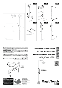
Q
g h i
J K L
R
M N O
P
S
U
T
T
X
V
W
D
T
C
Y
P
B
a
T
T
E f
g AC AB AA
AD AE
U
Entrata acqua fredda
Cold water inlet
Entrée eau froide
Entrata acqua calda
Hot water inlet
Entrée eau chaude
Z
Parete finita
Finish wall
Paroi finie
I Uscita acqua
I Outlet water
I Sortie eau
I
II Uscita acqua
II Outlet water
II Sortie eau
II
III Uscita acqua
III Outlet water
III Sortie eau
III
IV Uscita acqua
IV Outlet water
IV Sortie eau
IV
VERSIONE NPT / NPT VERSION /
fig. A
SMONTAGGIO VITONE
CARTUCCIA TERMOSTATICA
REMOVING MAIN SCREW
THERMOSTAT CARTRIDGE
DÉMONTAGE GROSSE VIS
CARTOUCHE THERMOSTATIQUE
AA AB
ISTRUZIONI DI MONTAGGIO
FITTING INSTRUCTIONS
A
M
O
fig. B
L
INSTRUCTIONS DE MONTAGE
C
D
K
J
I
SMONTAGGIO VALVOLE DI NON RITORNO
REMOVING THE CHECK VALVES
DÉMONTAGE CLAPET DE RETENUE
N
IMPORTANT
Pressure & Temperature Requirements.
• Hot and cold water inlet pressures should
be equal.
• Inlet pressure range: 150-1000 kPa
• New Regulation: -500 kPa maximum operating
pressure at any outlet within a building.
(Ref. AS/NZS 3500.1-2003, Clause 3.3.4)
• Maximum hot water temperature: 80°C.
iB Rubinetterie S.p.A.
Via dei Pianotti 3/5
25068 SAREZZO (BS) Italy
Iscr. Reg. Impr. BS 01785230986
R.E.A. BS 352087
P.IVA IT01785230986
Capitale Sociale € 420.000,00 i.v.
phone +39 030 802101
fax +39 030 803097
mail [email protected]
Shower
Euphoria
COMPONENTS LIST
LISTA DEI COMPONENTI
A
B
C
D
E
F
G
H
Maniglia uscita
Piolo maniglia
Grano M4x4
Placchetta
Piastra copertura
Guarnizione biadesiva
Vite
Carter copertura
I Vite M4x10
J Maniglia termo
K Fermo di regolazione
temperatura
L
M
N
O
P
Q
R
S
T
U
V
W
Anello scorriflangia termo
Cartuccia termostatica
Valvole di non ritorno
Grano M5x10
Tappi protezione
Bollino rosso
Bollino blu
Corpo termostatico
Dado esagonale M6
Oring 22.23x2.62
Inserto collegamento
Oring 16x2
X Spina centraggio Ø5 L14
Y Corpo collettore
Z Tappo G3/4”
AA Vitone ceramico G3/4”
AB Anello scoriflangia vitone
AC Carter copertura
AD Piastra fissaggio
AE Vite M6x50
DATI TECNICI
Pressione dinamica minima: Pressione di esercizio massima: Pressione di esercizio raccomandata: Si raccomanda di utilizzare un riduttore di pressione,
se all’interno dell’impianto si hanno pressioni statiche superiori a 5 bar.
Temperatura massima acqua calda:: PROVE DI PORTATA (38°C)
PRESSIONE bar
1
2
3
1 uscita aperta
l/m
23.8
33.5
41
2 uscite aperte
l/m
26.1
36.6
44.5
0.5 bar
10 bar
1-5 bar
80°C
3 uscite aperte
l/m
26.4
37.2
45.5
4 uscite aperte
l/m
26.6
37.4
45.7
A
B
C
D
E
F
G
H
Outlet handle
Handle pin
Stud bolt M4x4
Plaque
Cover plate
Biadhesive seal
Screw
Cover
I
J
K
L
Screw M4x10
Thermostat handle
Temperature setting stop
Thermostat flange
adjuster ring
P
Q
R
S
T
U
V
W
M Thermostat cartridge
N Check valve
O Stud bolt M5x10
Protective caps
Red mark
Blue mark
Thermostat unit
Nut M6
O-ring 22.23x2.62
Connection insert
O-ring 16x2
X Locator pin Ø5 L14
Y Manifold unit
Z Cap G3/4”
AA Ceramic main screw G3/4”
AB Main screw flange adjuster ring
AC Cover
AD Fixing plate
AE Screw M6x50
TECHNICAL DATA
Minimum dynamic pressure:
Maximum operational pressure:
Recommended operational pressure:
It is recommended to use a pressure reducer,
if inside the waterpipes there are static pressure superior to 5 bar
Maximumhot water temperature
FLOW RATE TESTS (38°C)
PRESSURE bar
1
2
3
1 outlet open
l/m
23.8
33.5
41
0.5 bar
10 bar
1-5 bar
80°C
2 outlets open
l/m
3 outlets open
l/m
26.1
36.6
44.5
4 outlets open
l/m
26.4
37.2
45.5
26.6
37.4
45.7
NORME DI INSTALLAZIONE, MANUTENZIONE E VERIFICHE PRELIMINARI
Perché il suo apparecchio funzioni nella maniera corretta e possa durare nel tempo, occorre che vengano rispettate
le modalità di installazione e manutenzione illustrate in questo opuscolo. Affidarsi ad un idraulico qualificato. Assicurarsi che l’impianto sia stato liberato da tutti i detriti e impurità esistenti.
INSTALLATION, MAINTENANCE AND PRELIMINARY CHECKING PROCEDURE
To ensure that the mixer tap unit functions correctly and lasts over time, the installation and maintenance procedures
illustrated in this leaflet must be complied with. Have all work done by a qualified plumber. Ensure that all debris and
dirt have been removed from the system.
PULIZIA
Per una corretta pulizia, lavare esclusivamente con acqua e sapone, risciacquare ed asciugare con una pelle di
daino o panno morbido. Evitare assolutamente l’impiego di alcool, solventi, detersivi solidi o liquidi contenenti sostanze corrosive o acide, strofinacci prodotti con fibre sintetiche, spugne abrasive e tamponi con fili metallici, poiché
potrebbero alterare irreversibilmente le superfici trattate.
CLEANING
To clean the unit correctly, use only soap and water, rinse and dry with a chamois leather or soft cloth. Never use
alcohol, solvents, solid or liquid detergents containing corrosive substances or acids, synthetic fibre rags, abrasive
sponges or steel wire scouring pads, since they may cause irreparable damage to the treated surfaces.
INSTALLAZIONE
Posizionare il corpo miscelatore nell’alloggiamento praticato nella parete ponendo particolare attenzione ai riferimenti per la posa MIN e MAX stampati sul coperchio di protezione h (N.B.: misure a parete finita compreso di
rivestimento). Estrarre i tappi in plastica P ed allacciarsi alle tubazioni della rete, ponendo particolare attenzione al
coretto collegamento calda fredda, come stampato sul corpo termostatico S . Collegare le 4 tubazioni superiori al
collettore 4 vie Y (3 tubazioni se si dispone del modello a 3 vie). Non coprire con cemento o altro materiale il corpo
termostatico S perché le 2 valvole N devono poter essere estratte per la ordinaria pulizia. Dopo aver collegato
il corpo all’impianto, aprire i rubinetti d’arresto e verificare il coretto funzionamento del termostatico. Controllare la
tenuta di tutti i collegamenti. Procedere poi con il montaggio della piastra di copertura e delle leve.
SMONTAGGIO VITONE - CARTUCCIA TERMOSTATICA (fig. A)
Chiudere le entrate del’acqua calda e fredda. Smontaggio vitone AA : rimuovere il cappuccio D , svitare il grano C , sfilare la maniglia A , svitare lo scorriflangia AB e il vitone AA . Per il montaggio procedere in ordine
inverso, assicurandosi che la base di appoggio del vitone all’interno del collettore 4 vie sia accuratamente pulita.
Smontaggio cartuccia termostatica M : svitare la vite I , sfilare la maniglia J e il fermo di regolazione temperatura K , svitare l’anello scoriflangia L , svitare il grano filettato O , sfilare la cartuccia termostatica M . Per
il montaggio procedere in ordine inverso, assicurandosi che la sede della cartuccia sia accuratamente pulita.
Smontaggio valvolE di non ritorno (fig. B)
Chiudere le entrate dell’acqua fredda e calda. Svitare le valvole di non ritorno ruotando in senso antiorario N .
Pulire rimuovendo le impurità. Rimontarle nel corpo assicurandosi che la sede sia accuratamente pulita.
INSTALLATION
Place the body of the mixer tap unit in the cavity provided in the wall, taking care to refer to the MIN and
MAX installation markings printed on the protective cover H (N.B.: measurements refer to the finished
wall, complete with covering). Remove the plastic caps P and connect to the system pipes, taking special care to connect the hot and cold water correctly, as marked on the thermostat unit S . Connect the 4
top pipes to the 4-way manifold Y (3 pipes with the 3-way model). Do not cover the thermostat unit S
with cement or other materials, because it must be possible to remove the 2 valves N for routine cleaning. After connecting the body of the unit to the system, turn on the stop taps and check that the thermostat
operates correctly. Check that all the connections are watertight. Then fit the cover plate and the levers.
REMOVING MAIN SCREW / THERMOSTAT CARTRIDGE (fig. A)
Turn off the hot and cold water intakes. Removing the main screw AA : remove the cover D , undo the stud bolt
C , extract the handle A and unscrew the flange collar AB and the main screw AA . To reassemble, reverse the
above procedure, making sure that the main screw contract surface inside the 4-way manifold is thoroughly cleaned. Removing the thermostat cartridge M : unscrew the screw I , remove the handle J and the temperature
setting stop K , unscrew the flange adjuster ring L , unscrew the stud bolt O and extract the thermostat cartridge M . To reassemble, reverse the above procedure, making sure that the cartridge seat is thoroughly cleaned.
REMOVING THE CHECK VALVES (fig. B)
Turn off the hot and cold water intakes. Unscrew the check valves by turning them anticlockwise N . Clean them to
remove dirt. Reassemble them in the body, making sure that the seat is thoroughly clean.
LISTE DES PIÈCES
A
B
C
D
E
F
G
H
Bouton de sortie
Broche poignée
Vis sans tête M4x4
Platine
Plaque de recouvrement
Joint bi-adhésif
Vis
Carter
I Vis M4x10
J Poignée thermostatique
K Bague de réglage
température
L
M
N
O
Bague bride thermostatique
Cartouche thermostatique
Clapet de retenue
Vis sans tête M5x10
P
Q
R
S
T
U
V
W
Bouchons de protection
Pastille rouge
Pastille bleue
Corps thermostatique
Écrou hexagonal M6
Anneau torique 22.23x2.62
Insert raccordement
Anneau torique 16x2
X Fiche de centrage Ø5 L14
Y Corps collecteur
Z Bouchon G3/4”
AA Tige céramique G3/4”
AB Bague bride tige
AC Carter
AD Plaque de fixation
AE Vis M6x50
CARACTÉRISTIQUES TECHNIQUES
Pression dynamique mini.:
Pression maxi. d’exercice:
Pression d’exercice recommandée:
Il est recommandé d’utiliser un réducteur de pression en cas
de pressions statiques supérieures à 5 bars dans l’installation.
Température maxi. eau chaude:
TESTS DE DÉBIT (38°C)
PRESSION bar
1
2
3
Y
Z
Q
R
S
T
U
V
W
X
AA
AB
AC
AD
AE
I
J
K
L
M
N
O
P
0.5 bar
10 bar
1-5 bar
80°C
(38°C)
1 sortie ouverte 2 sorties ouvertes 3 sorties ouvertes 4 sorties ouvertes
l/m
l/m
l/m
l/m
23.8
33.5
41
26.1
36.6
44.5
A
B
C
D
E
F
G
H
26.4
37.2
45.5
26.6
37.4
45.7
NORMES D’INSTALLATION, D’ENTRETIEN ET VÉRIFICATIONS PRÉLIMINAIRES
Pour que votre appareil fonctionne correctement et dure dans le temps, il est nécessaire de respecter les modalités
d’installation et d’entretien illustrées dans cet opuscule. Demander l’intervention d’un plombier qualifié. Vérifier que
l’installation est libre de tous détritus et de toutes impuretés.
3
1
2
3
23.8
33.5
41
4
/
26.1
36.6
44.5
/
26.4
37.2
45.5
26.6
37.4
45.7
NETTOYAGE
Pour un nettoyage correct, laver exclusivement à l’eau savonneuse, rincer et essuyer avec une peau de chamois ou
un chiffon doux. Éviter l’emploi d’alcool, solvants, produits détergents solides ou liquides contenant des substances
corrosives ou acides, les chiffons synthétiques, les éponges abrasives et les pailles de fer, étant donné qu’ils peuvent endommager irrémédiablement les surfaces traitées.
INSTALLATION
Positionner le corps du mitigeur dans le logement pratiqué dans le mur en observant rigoureusement les repères de pose MIN et MAX imprimés sur le couvercle de protection h (N.B. mesures correspondant au mur
revêtu fini). Retirer les bouchons en plastique P et les installer sur les conduites en prêtant attention au raccordement eau chaude/eau froide indiqué sur le corps thermostatique S . Raccorder les 4 conduites supérieures au collecteur 4 voies Y (3 conduites avec le modèle à 3 voies). Ne pas couvrir le corps thermostatique S de ciment ou d’un autre matériau, les 2 valves N devant pouvoir être retirées en vue du nettoyage.
Après avoir raccordé le corps à l’installation, ouvrir les robinets d’arrêt et vérifier le fonctionnement thermostatique.
Contrôler l’étanchéité de tous les raccords. Procéder ensuite au montage de la plaque de recouvrement et des leviers.
DÉMONTAGE TIGE / CARTOUCHE THERMOSTATIQUE (fig. A)
Fermer les entrées de l’eau chaude et froide. Démontage tige AA : retirer le capuchon D , desserrer la vis sans tête
C , retirer la poignée A , dévisser le support bride AB et la tige AA . Pour le montage, effectuer les mêmes opérations en sens inverse en vérifiant que le support de la tige dans le collecteur 4 est parfaitement propre. Démontage
cartouche thermostatique M : retirer la vis I , la poignée J et la bague de réglage température K , dévisser le
support bride L , desserrer la vis sans tête filetée O , retirer la cartouche thermostatique M . Pour le montage, effectuer les mêmes opérations en sens inverse en vérifiant que le logement de la cartouche est parfaitement propre.
DÉMONTAGE CLAPET DE RETENUE (fig. B)
Fermer les entrées de l’eau chaude et froide. Dévisser les clapets de retenue dans le sens inverse des aiguilles
d’une montre N . Nettoyer toutes les impuretés. Remonter le tout après avoir vérifié que le logement est parfaitement propre.
h
P
S
Y
N
S
(fig. A)
AA
AB
K
A
C
D
I
J
M
AA
M
O
(fig. B)
N
L
Scaricare