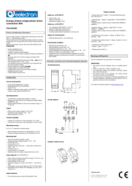
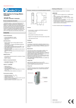
PM10A01KNXFI01010001.doc
Display (readouts)
• Operational voltage V 300
Energy-meters single-phase with
KNX Interface
PM10A00IRE
Safety acc. to EN 5047050470-1
• AC voltage test (EN 50470-3, 7.2) kV 4
• Impulse voltage test 1.2/50 µs-kV 6
• Protection class (EN 50470) class II
• Housing material flame resistance UL 94 class V0
• Safety-sealing between upper and lower housing part (mod.
282551) – yes
• Display type LCD n° digits 7 (1 decimal digit dimensions
mm x mm 6.00 x 3
Adaptor for Communication
• Reactive energy: 1 display, 7-digit tariffs 1-2 kvarh
000000.0 ... 999999.9
+ display import or export (arrow) overflow kvarh 999999.9 ...
000000.0
• EIB-KNX EIB-standard - up to 9.600 bps
Product and Applications Description
Active energy-meters for single-phase alternating current with
either 1, 7 digits digital counters.
These meters have 2 S0 output generating pulses for remote
processing of the energy active and reactive measurements for
2 tariff.
• Green backlighted LCD
• For direct connection 80 A
• 7 digits for energy values indication
• Accuracy class 1 for active energy according to EN 50470-3
(B)
• Accuracy class 2 for reactive energy according to EN 6205323
• Most actrative operating range current (Ist
Ist ... Imax.)
Imax.
for direct connection 80 A = 0.02 ... 80 A
• The standard versions are designed to be combined with the
communication module
• Energy register zero setting (NO MiD)
• Energy register for import and export
• Instantaneous power active and reactive display
• Sealable terminal covers
• 2 DIN modules wide (36 mm)
Technical Data
Data
• Active energy: 1 display, 7-digit tariffs 1-2 kWh 000000.0 ...
999999.9
+ display import or export (arrow) overflow kWh 999999.9 ...
000000.0
Connection terminals
• Type cage main current paths screw head Z +/- POZIDRIV PZ2
• Type cage pulse output blade for slotted screw mm 0.8 x 3.5
• Terminal capacity main current paths solid wire min. (max.) mm
2 1.5 (35) stranded wire with sleeve min. (max.) mm2 1.5 (35)
• Terminal capacity pulse outlet solid wire min. (max.) mm2 0.14
(2.5) stranded wire with sleeve min. (max.) mm2 0.14 (1.5)
Environmental conditions
• Mechanical environment - M1
• Electromagnetic environment - E2
• Operating temperature °C -10 ... +55
• Limit temperature of transportation and storage °C -25 ... +70
• Relative humidity (not condensation) % _80
• Vibrations 50 Hz sinusoidal vibration amplitude mm ±0.075
• Degree protection housing when mounted in front (terminal) IP51(**)/IP20
Terminals, connections and command/visualisation elements
Overall Dimensions:
General characteristics
• Housing DIN 43880 DIN 2 modules
• Mounting EN 60715 35 mm DIN rail
• Depth 70 mm
• Reference standard active energy - EN 50470-1-3, reactive
energy - pulse output EN 62053-23-31
• Instantaneous active power: 1 display, 3-digit W, kW or
MW 000 ... 999
• Instantaneous reactive power: 1 display, 3-digit var, kvar or
Mvar 000 ... 999
• Instantaneous tariff measurement – 1
1 display, 1-digit - T1 or T2
• Display period refresh s 1
Mounting and Wiring hints
Device is intended to be used indoor in dry places.
IMPORTANT:
IMPORTANT:
• This device must be installed only by a qualified electrician.
• Install in conformity to SELV installation rules.
• The applicable safety and accident prevention regulations must be observed.
• The device must not be opened. Any faulty devices
should be returned to manufacturer.
• For planning and construction of electric installations, the
relevant guidelines, regulations and standards of the respective country are to be considered.
For further information please visit www.eelectron.com
Operating features
• Connectivity to single-phase network n° wires 2
• Storage of energy values and configuration digital display
(EEPROM) - yes
• Display tariffs identifier for active and reactive energy n° 2 T1
and T2
Supply
Circuits Diagram:
• Rated control supply voltage Un VAC 230
• Operating range voltage V 184 ... 276
• Rated frequency fn Hz 50
• Rated power dissipation (max.) Pv VA (W) _8 (0.6)
Overload capability
• Voltage Un continuous V 276 momentary (1 s) V 300
• Current Imax continuous A 80 momentary (10 ms) A 2400
Measuring accuracy
At 23 ±1°C, referred to nominal values
• Active energy and power acc.to EN 50470-3 % ±1 (B)
• Reactive energy and power acc.to EN 62053-23 % ±2
Measuring input
• Type of connection phase/N - direct
• Operating range voltage phase/N V 184 ... 276
• Current Iref A 15
• Current Imin A 0.75
• Operating range current (Ist ... Imax) direct connection A
0.025 ... 80
• Frequency Hz 50
• Input waveform - sinusoidal
• Starting current for energy measurement (Ist) mA 25
Sealable Terminal Covers:
Pulse output S0 acc.to EN 62053-31
• Pulse output for active and reactive energy T1 and T2 - yes
• Pulse quantity imp/kWh 1000
• Pulse duration ms 30 ±2 ms
• Required voltage min. (max.) VAC (DC) 5 ... 230 ±5% (5 ...
300)
• Permissible current pulse ON (max. 230 V AC/DC) mA 90
• Permissible current Impuls OFF (leakage cur. max. 230 V
AC/DC) µA 1
Optical interfaces
• Front side (accuracy control) LED imp/kWh 1000
Safety acc. to EN 5047050470-1
• Indoor meter - yes
• Degree of pollution - 2
eelectron spa
Via Magenta 77/22
I-20017 Rho (MI) - Italia
Email: [email protected]
Web: www.eelectron.com
PM10A01KNXFI01010001.doc
Sicurezza secondo EN 50470-1
Contatore Monofase con
Interfaccia KNX
PM10A00IRE
Descrizione sintetica del prodotto e suo funzio
funzionamento
Contatori di energia attiva per corrente alternata monofase con numeratori digitali fino a 7 cifre.
Questi contatori presentano 2 uscite S0 e 2 tariffe che
generano impulsi per l’elaborazione remota delle misurazioni dell’energia attiva e reattiva istantanea.
• Visualizzatore a cristalli liquidi con sfondo illuminato di
colore verde
• Collegamento diretto a 80 A
• Display da 7 digit per i valori dell’energia totalizzata
• Classe 1 di precisione per energia attiva secondo la
norma EN 50470-3 (B)
• Classe 2 di precisione per energia reattiva secondo la
norma EN 62053-23
• Campo di corrente (Ist ... Imax) per connessione diretta
80 A = 0.02 ... 80 A
• Versioni standard predisposte per essere abbinate al
modulo per la comunicazione
• Registri contatori azzerabili (NO MiD)
• Registri d’energia assorbita o erogata
• Indicazione della potenza momentanea attiva e reattiva
• Copertura morsetti piombalile
• 2 moduli DIN (36 mm)
• Tensione di prova (EN 50470-3, 7.2) kV 4
• Prova tensione di impulso 1.2/50 µs-kV 6
• Classe di protezione (EN 50470) classe II
• Resistenza della custodia alla fiamma UL 94 classe V0
• Protezione meccanica - sigillo fra custodia e base (mod.
282551)
Moduli aggiuntivi per la comunicazione
• EIB-KNX EIB-standard - fino a 9.600 bps
• Display LCD n° digits 7 (1 decimale) dimensione digit
mm x mm 6.00 x 3
• Energia attiva: 1 indicatore, 7 cifre 2 tariffe kWh
000000.0 ... 999999.9
+ indicazione assorbita o erogata (freccia) flusso massimo
kWh 999999.9 ... 000000.0
• Energia reattiva: 1 indicatore, 7 cifre 2 tariffe kvarh
000000.0 ... 999999.9
+ indicazione assorbita o erogata (freccia) flusso massimo
kvarh 999999.9 ... 000000.0
Morsetti
• Tipo di gabbia morsetto corrente principale testa della
vite Z +/- POZIDRIV PZ2
• Tipo di gabbia morsetto uscita impulso testa della vite a
taglio mm 0.8 x 3.5
• Capacità morsetto corrente principale filo compatto min.
(max.) mm2 1.5 (35) filo flessibile con capocorda min.
(max.) mm2 1.5 (35)
• Capacità morsetto uscita impulso filo compatto min.
(max.) mm2 0.14 (2.5) filo flessibile con capocorda min.
(max.) mm2 0.14 (1.5)
• Potenza attiva istantanea: 1 indicatore, 3 cifre W, kW o
MW 000 ... 999
• Potenza reattiva istantanea: 1 indicatore, 3 cifre var,
kvar o Mvar 000 ... 999
• Tariffa attuale - 1
1 indicatore, 1 cifra - T1 o T2
• Ciclo di visualizzazione s 1
Avvertenze per l‘installazione
Condizioni ambientali
• Ambiente meccanico - M1
• Ambiente elettromagnetico - E2
• Temperatura d’impiego °C -10 ... +55
• Limite della temperatura di immagaz. e trasporto °C -25
... +70
• Umidità relativa (non condensata) % _80
• Vibrazioni ampiezza vibrazioni sinusoidali 50 Hz mm
±0.075
• Grado di protezione apparecchio montato frontalmente
(morset ti) - IP51(*)/(IP20)
Dati tecnici
Posizione indicatori ed elementi di co
comando
Caratteristiche generali
Visualizzazione (lettura)
L’apparecchio deve essere impiegato per installazione in
ambienti chiusi e asciutti.
IMPORTANTE
• L’apparecchio deve essere installato e messo in servizio da un installatore abilitato.
• Devono essere osservate le norme in vigore in materia
di sicurezza e prevenzione antinfortunistica.
• Installare il prodotto senza compromettere la sicurezza
SELV del BUS
• L’apparecchio non deve essere aperto. Eventuali apparecchi difettosi devono essere fatti pervenire alla
sede competente.
Dimensioni:
• Custodia DIN 43880 DIN 2 moduli
• Fissaggio EN 60715 35 mm binario DIN
• Profondità mm 70
• Norme di riferimento energia attiva - EN 50470-1-3
reattiva di energia - impulso di uscita EN 62053-23-31
Per ulteriori informazioni visitate: www.eelectron.com
Funzionamento
• Connessione a rete monofase n° fili 2
• Memorizzazione energia misurata e configurazione a
mezzo numeratore digitale (EEPROM) - si
• Tariffe per energia attiva e reattiva n° 2 T1 o T2
Alimentazione
• Tensione nominale di alimentazione Un VAC 230
• Campo di variazione tensione V 184 ... 276
• Frequenza nominale fn Hz 50
• Potenza assorbita (max.) Pv VA (W) _8 (0.6)
Sovraccaricabilità
Schemi di Collegamento:
• Tensione Un permanente V 276 momentanea (1 s) V
300
• Corrente Imax permanente A 80 momentanea (10 ms) A
2400
Precisione a 23 ±1°C riferimento ai valori nominali
• Energia e potenza attive secondo EN 50470-3 % ±1 (B)
• Energia e potenza reattive secondo EN 62053-23 % ±2
Ingressi di misura
• Inserzione fase/N - diretta
• Campo di tensione fase/N V 184 ... 276
• Corrente Iref A 15
• Corrente Imin A 0.75
• Campo di corrente (Ist ... Imax) connessione diretta A
0.025 ... 80
• Frequenza Hz 50
• Forma d’onda in ingresso - sinusoidale
• Corrente iniziale per la misura di energia (Ist) mA 25
Copertura Morsetti Plombabili:
Uscita S0 secondo EN 62053-31
• Uscita impulso per energia attiva e reattiva - si
• Quantità impulso imp/kWh 1000
• Durata impulso ms 30 ±2 ms
• Tensione necessaria min. (max.) VAC (DC) 5 ... 230
±5% (5 ... 300)
• Corrente consentita impulso ON (max. 230 VAC/DC) mA
90
• Corrente consentita impulso OFF (corrente di dispersione max. 230 VAC/DC) µA 1
Interfaccia ottica
• Calibratura frontale (controllo di precisione) LED
imp/kWh 1000
Sicurezza secondo EN 50470-1
• Installazione per interni - si
• Classe inquinamento - 2
• Tensione di funzionamento V 300
eelectron spa
Via Magenta 77/22
I-20017 Rho (MI) - Italia
Email: [email protected]
Web: www.eelectron.com
PM10A01KNXFI01010001.doc
Terminals, connections and command/visualisation elements
Mounting and Wiring hints
Device is intended to be used indoor in dry places.
IMPORTANT:
IMPORTANT:
KNX Interface for
• This device must be installed only by a qualified electrician.
• Install in conformity to SELV installation rules.
• The applicable safety and accident prevention regulations must be observed.
• The device must not be opened. Any faulty devices
should be returned to manufacturer.
• For planning and construction of electric installations, the
relevant guidelines, regulations and standards of the respective country are to be considered.
PM00A00IRI
Product and Applications Description
The EIB-KNX interface (1 module wide, DIN rail mount) is intended for connecting the energy meter to EIB-KNX bus.
EIB-KNX bus is widely used for home and building control applications. The interface receives the measurement data from
the energy meter by means of the infrared port available on
the side of the energy meter itself, and gets the power supply
from the bus. Only the bus wiring (twisted pair) must be connected, no additional wiring is requested. The interface is suitable for both single-phase and three-phase energy meters.
Technical Data
For further information please visit www.eelectron.com
Overview
• Model available:
- type: for energy register and power measurements
General characteristics
• Housing DIN 43880 DIN 1 module
• Mounting EN 60715 35 mm DIN rail
• Depth mm 70
Operating features
• Models available: type: for energy register and power measurements
• Communication in compliance with EIB-KNX standard for
home and buiding control
• Energy registers transmitted as float values (DPT 13. xxx)
• Power registers transmitted as float values (DPT 14. xxx)
• Status bytes available
• Energy account remote reset available (not active some
energy meters models)
• Suitable for both single-phase and three-phase energy meters - yes
• Configuration via ETS3
• Communication in compliance with EIB-KNX standard for home
and buiding control
• Configuration via ETS3
• Energy registers transmitted as float values (EIS9)
• Suitable for both single-phase and three-phase energy meters
• 1 DIN module wide (18 mm)
Function:
Configuration
The interface is provided with an application program to be imported in ETS3, in order to allow the configuration of the communication. ETS3 is the standard software for EIB-KNX systems
configuration.
EIB-KNX interface
Measurements
• HW interface - black/red terminals for connection to Twisted
Pair type 1 (TP-1)
• Bitrate - 9600 bps
All the active and reactive energy registers available on the measuring instrument can be transmitted over the bus.
Transmission modes are available: transmission on request, automatic transmission based on adjustable energy account increment (for instance a message every 10 KWh).
Status bytes are available as well, containing information about
the status of the energy meter and the load (load type, running
Tariff, energy import or export and so on).
(Some measurements and status information are available only
on selected models)
Interface to measuring instrument
• HW interface optical IR n° 2 (Tx, Rx)
• SW protocol – proprietari
Safety acc. to EN 60664
• Degree pollution - 2
• Overvoltage category - II
• Working voltage VDC (max.) 30
• Clearance mm _1.5
• Creepage distance in equipment mm _2.1
on printed wiring boards (not coated) mm _1.5
• Test voltage impulse (1,2/50 µs) peak value kV 2.5
50 Hz 1 min kV 1.35
• Housing material flame resistance UL 94 class V0
Voltage limits
Upper and lower voltage limits can be set via ETS3.
A warning message will be sent over the bus by the interface, in
case the voltage value goes beyond the limits.
Energy reset
Commands can be sent via bus to the interface for resetting the
energy accounts (Enabled only on selected measuring instruments models).
Environmental conditions
• Operating temperature °C 0 ... +55
• Temperature of storage °C -25 ... +70
• Relative humidity % _80
• Vibrations sinusoidal vibration amplitude at 50 Hz mm ±0.25
• Protection class acc.to EN 60664 - II
• Degree of protection housing when mounted - IP20
eelectron spa
Via Magenta 77/22
I-20017 Rho (MI) - Italia
Email: [email protected]
Web: www.eelectron.com
PM10A01KNXFI01010001.doc
Posizione indicatori
indicatori ed elementi di co
comando
Avvertenze per l‘installazione
L’apparecchio deve essere impiegato per installazione in ambienti chiusi e asciutti.
IMPORTANTE
Interfaccia KNX per
• L’apparecchio deve essere installato e messo in servizio da
un installatore abilitato.
• Devono essere osservate le norme in vigore in materia di
sicurezza e prevenzione antinfortunistica.
• Installare il prodotto senza compromettere la sicurezza
SELV del BUS
• L’apparecchio non deve essere aperto. Eventuali apparecchi difettosi devono essere fatti pervenire alla sede competente.
PM00A00IRI
Descrizione sintetica del prodotto e suo funzio
funzionamento
L’interfaccia EIB-KNX (montaggio su barra DIN, larghezza 1
modulo) consente di connettere i contatori di energia elettrica
al bus EIB-KNX.
EIB-KNX è uno standard largamente usato per il controllo degli
edifici. L’interfaccia è alimentata dal bus stesso, e riceve i dati
di misura dal contatore a cui viene affiancata tramite la porta
ottica IR disponibile sul fianco del contatore. L’unica connessione elettrica richiesta è quella al cavo del bus. L’interfaccia è
utilizzabile sia con contatori monofase che trifase
Dati tecnici
Caratteristiche generali
• Custodia DIN 43880 DIN 1 modulo
• Fissaggio EN 60715 35 mm binario DIN
• Profondità mm 70
Alimentazione
• Alimentazione - tramite bus
Funzionamento
• Due modelli disponibili: tipo: trasmissione di dati su energia e
potenza
• Comunicazione secondo lo standard EIB-KNX per il controllo
degli edifici
• Registri energia trasmessi come valori float (DPT 13. xxx)
• Registri potenza trasmessi come valori float (DPT 14. xxx)
• Bytes di stato trasmessi
• Azzeramento remoto dei conteggi di energia (solo su alcuni
modelli)
• Utilizzabile sia con strumenti monofase che con strumenti trifase - si
• Configurazione tramite ETS3
Interfaccia EIB-KNX
• Interfaccia HW - terminale nero/rosso per connessione a
doppino tipo 1 (TP-1)
• Velocità di trasmissione - 9600 bps
Interfaccia verso gli strumenti di misura
• Interfaccia HW ottica IR n° 2 (Tx, Rx)
• Protocollo SW - proprietario
Sicurezza secondo EN 60664
Descrizione:
• Modello disponibile:
- tipo: trasmissione di dati su energia e potenza
• Comunicazione secondo lo standard EIB-KNX per il controllo
degli edifici
• Configurazione tramite ETS3
• Registri energia trasmessi come valori float (EIS9)
• Utilizzabile sia con strumenti monofase che con strumenti trifase
• 1 modulo DIN (18 mm)
Per ulteriori informazioni visitate: www.eelectron.com
Funzione
Configurazione
Per l’interfaccia è disponibile un “database entry” da importare
in ETS3 per consentire la configurazione della
comunicazione. ETS3 è il software standard per la configurazione di sistemi EIB/KNX.
Misure
Tutti i registri di energia attiva e reattiva disponibili nel contatore possono essere trasmessi tramite bus.
Diverse modalità di trasmissione sono selezionabili: trasmissione a richiesta, trasmissione automatica a intervalli di
energia configurabili (ad esempio un messaggio ogni 10 KWh).
Sono anche disponibili dei byte di stato contenenti informazioni
sullo strumento e sul carico (tipo di carico, tariffa
attualmente attiva, informazione su import/export di energia
etc.) Alcune misure e informazioni sono disponibili o meno a
secondo del modello di contatore.
Limiti di tensione
Un limite inferiore e superiore sulla tensione possono essere
impostati via ETS3.
In caso di superamento da parte della tensione misurata
l’interfaccia invia un messaggio sul bus.
Comandi
Comandi di azzeramento remoto dell’energia conteggiata possono essere inviati via bus.
I comandi di azzeramento sono attivi solo per alcuni modelli di
contatori.
• Grado di inquinamento - 2
• Categoria di sovratensione - II
• Tensione di funzionamento VDC (max.) 30
• Distanza in aria mm _1.5
• Distanza superficiale dispositivo (apparecchio) mm _2.1
dispositivo (non coperto) mm _1.5
• Prova di tensione valore di picco dell’impulso (1,2/50 µs) kV
2.5 tensione di prova 50 Hz 1 min. kV 1.35
• Resistenza della custodia alla fiamma UL 94 classe V0
Condizioni ambientali
• Temperatura di impiego °C 0 ... +55
• Temperatura di immagazzinaggio °C -25 ... +70
• Umidità relativa % _80
• Vibrazioni ampiezza vibrazione sinusoidale a 50 Hz mm ±0.25
• Classe di protezione secondo EN 60664 - II
• Grado di protezione apparecchio montato - IP20
eelectron spa
Via Magenta 77/22
I-20017 Rho (MI) - Italia
Email: [email protected]
Web: www.eelectron.com
Scaricare