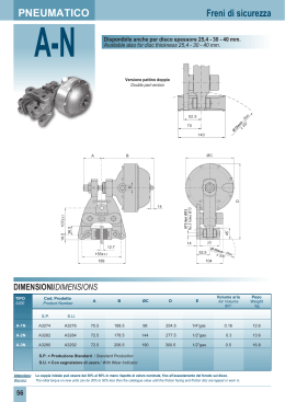
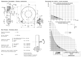
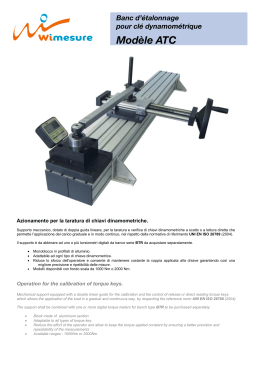
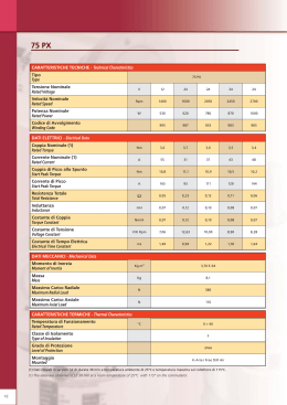
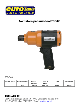
PNEUMATICO
Freni di sicurezza
EL-N
170±0.1
N°3 fori Ø17
No.3 holes Ø17
85
170±0.1
Vista montaggio frontale
Frontal mounting view
ØC
B
30
F
A
30
42
E
122
177.5± 0.1
35
34
80.5
40
17±0.1
170± 0.1
G
D
Ø17
17
22
250± 0.1
147
117
295
Ø Disc
o
- Disc ≥
610
DIMENSIONI/DIMENSIONS
Volume aria Peso
TIPO
Cod. Prodotto
A BØC D E
F G
Volume Weight
SIZE
Product NumberAir

dm3
kg
EL-3N
A3587
126 227 190 41825.4 1/2”gas 14
0.7
64
A3590
126
0.7
64
EL-3.5N A3593
EL-4N
227
190
418
40
1/2”gas
14
127 242 240 44325.4 1/2”gas 16 0.95 68.5
A3596
127
242
A3599
135 289 280 46325.4 1/2”gas 16
3
73
A3602
135
3
73
289
240
280
443
463
40
40
1/2”gas
1/2”gas
16
16
Attenzione: La coppia iniziale può essere dal 30% al 50% in meno rispetto al valore nominale, fino all’assestamento del ferodo sul disco.
Warning: The initial torque on new units can be 30% to 50% less than the catalogue value until the friction facing and friction disc are lapped or worn in.
64
0.95
68.5
PNEUMATIC
Spring applied pneumatically released
Dati tecnici
Forza tangenziale F:
EL-3N
EL-3N 14150 N
EL-3.5N 26600 N
EL-4N
32000 N
EL-3.5N
DIAMETRO DISCO mm
DISC DIAMETER mm
COPPIA Nm
TORQUE Nm
COPPIA Nm
TORQUE Nm
DIAMETRO DISCO mm
DISC DIAMETER mm
Coppia dinamica
= F • (raggio del disco in m - 0.065) = Nm
USURA TOTALE mm
TOTAL WEAR mm
USURA TOTALE mm
TOTAL WEAR mm
COPPIA Nm
TORQUE Nm
DIAMETRO DISCO mm
DISC DIAMETER mm
EL-4N
Usura max totale: 12 mm
Spessore del ferodo nuovo: 13 mm
Dissipazione del calore in continuo
Qc: 20 kW
Pressione minima di apertura: 5 bar
I valori di coppia indicati sono
ottenuti con:
n. 8 molle per 3N,
n. 12 molle per 3.5N e 4N.
Coppie proporzionalmente inferiori si
possono ottenere con:
n. 6-4-2 molle per 3N,
n. 10-8-6 molle per 3.5N e 4N.
Il grafico rappresenta l’andamento
della coppia per ogni millimetro
di usura dei ferodi.
Per ripristinare il valore
nominale della coppia intervenire
sul sistema di regolazione.
Technical data
Braking force F:
EL-3N EL-3.5N EL-4N 14150 N
26600 N
32000 N
Dynamic torque
= F • (disc radius in m - 0.065) = Nm
Max total wear: 12 mm
USURA TOTALE mm
TOTAL WEAR mm
DIAGRAMMA/CHART
Dissipazione
di calore
per frenatura
di emergenza
Thickness of new lining: 13 mm
Continuous thermal capacity
Qc: 20 kW
Minimum release pressure: 5 bar
The torque values specified
are obtained with
No. 8 springs for 3N,
No. 12 springs for 3.5N and 4N.
Torque proportionally less
are achievable with
No. 6-4-2 springs for 3N,
No. 10-8-6 springs for 3.5N and 4N.
The diagram shows the torque
variation for each millimeter
of linings wear.
Adjust according to ensure the
correct torque value is achieved.
Thermal capacity
for emergency stop
65
Scaricare