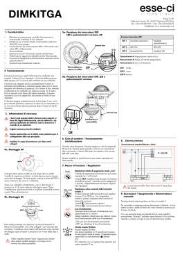
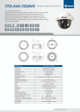
Art.4283 Functional to Digital interface with built-in speaker unit camera
Art.4283 Modulo d’interfaccia con portiere elettrico e telecamera incorporati
Balance
Art.4283-0
H
ON
L
L
1 2 3 4 5 6 7 8 9 10
sw
NC
PTE
GND
V/V2
V1
C
1 2 3 4 A B CD E F GH
BS
SL
NO
J2 J3
L
J1
H
GND
+12
GND
Art.4283-1
Art.4283-1D
Blue common - Blu comune
ON
1 2 3 4 5 6 7 8 9 10
SW
Not used - Non usato
Unit ID 1..8 - Indirizzo unità 1..8
Door Opening Time OFF=1s, ON=6s - Tempo di apertura porta OFF=1s, ON = 6s
Conversation Time OFF=60s, ON=120s - Tempo di conversazione OFF=60s, ON=120s
Push buttons address range - Intervallo indirizzi pulsanti
Master/Slave OFF=SLAVE, ON=MASTER - Master/Slave OFF=SLAVE, ON=MASTER
J1 Door Relay Mode - Modo relé apri-porta
H
= Capacitor discharge - Scarica capacitiva
L
H
L
= Dry contacts relay - Relé a contatti puliti
Yellow P1 - Giallo P1
Red P2 - Rosso P2
J2,J3 Video mode - Modo video
H
= Balanced Video Signal - Segnale video bilanciato
L
H
L
= Coax Video Signal - Segnale Video Coassiale
8+n 16+n 24+n 32+n
ON
1 2 3 4 5 6 7 8 9 10
H
ON
1 2 3 4 5 6 7 8 9 10
G
ON
1 2 3 4 5 6 7 8 9 10
F
ON
1 2 3 4 5 6 7 8 9 10
E
D
C
B
1+n
9+n 17+n 25+n
ON
1 2 3 4 5 6 7 8 9 10
ON
1 2 3 4 5 6 7 8 9 10
ON
1 2 3 4 5 6 7 8 9 10
ON
1 2 3 4 5 6 7 8 9 10
n=0
n = 32
n = 64
n = 96
n = 128
n = 160
n = 0 (900 series)
n = 32 (900 series)
A
4
3
2
1
35
VIDEX ELECTRONICS S.p.A.
VX2200 “2 WIRE” Bus Digital System
VX4283/0-1-1D MODULO D’INTERFACCIA PULSANTI TRADIZIONALI / SISTEMA "BUS 2FILI” CON TELECAMERA INCORPORATA
VX4283/0-1-1D DIGITAL TO FUNCTIONAL INTERFACE MODULE / “2 WIRE BUS” SYSTEM WITH
BUILT-IN CAMERA
Descrizione
Il VX4283 è un’unità di chiamata digitale su BUS “2 fili” che permette la
connessione di pulsanti tradizionali al sistema digitale VX2200.
L’unità è alloggiata in un modulo Serie 4000 e la sua elettronica si compone
dell’interfaccia analogico-digitale, del portiere elettrico con 0, 1 o 2 pulsanti
in base al modello ed in corpora una telecamera bianco e nero CCD autofocus
comprensiva di LED di illuminazione agli infrarossi (a luce bianca per le versioni con telecamere a colori). Le finiture disponibili per il modulo sono le
stesse di tutta la “Serie 4000”: placca frontale in acciaio inossidabile lucidato
a specchio (finitura standard) ed in alluminio anodizzato (aggiungere /A al
codice prodotto). L’interfaccia permette il collegamento di 32 pulsanti tradizionali impiegando i moduli di chiamata standard Serie 4000: Art.4842,
4843, 4844, 4845 e le relative versioni pulsanti doppi 4842D, 4843D, 4844D
e 4845D. Al numero dei pulsanti necessari alla composizione del posto esterno vanno sempre sottratti quelli presenti nel modulo (0,1 o 2 in base al modello). I pulsanti presenti nel modulo 1 o 2 (4283-1, 4283-1D), sono configurati di fabbrica rispettivamente come 1º ID Citofono o come 1º e 2º del gruppo di indirizzi impostato tramite gli switch 2, 3 e 4 del dip-switch a 10 vie.
Operando sui fili che fuoriescono dall’unità è possibile configurare differentemente i pulsanti del modulo. I moduli vanno assemblati utilizzando le scatole da incasso o superficie della serie 4000.
Il VX4283 funziona con tutti i citofoni e videocitofoni specifici per il sistema
VX2200 della serie 900, 3000 (esclusi i modelli 316XB) o 5000.
Description
The VX4283 unit is a digital front panel based on a “2 wire” BUS intercom
system that enables the connection of traditional push buttons. This unit is
housed in a single4000 series module and is available in Mirror Stainless
Steel (standard finish) or anodized aluminium (add /A after the product
code). It incorporates the functional interface connections from functional to
digital, the speaker unit module with 0, 1 or 2 call buttons and includes an
high quality B&W CCD Camera with autoiris lens and infrared illumination
LEDs (white light LEDs for colour camera version).
This device enables the connection of up to 32 functional push buttons using
standard 4000 series extension module panels Art.4842, 4843, 4844, 4845
and relevant double button version 4842D, 4843D, 4844D and 4845D. The
push buttons already fitted to the module are to be subtracted from the number of those to be inserted, i.e. 2 or 1 according to the model.
The module built-in buttons, 1 or 2 (4283-1 or 4283-1D) as factory presetting
are set as 1st ID PHONE or 1st and 2nd of the addresses group selected by dipswitches 2, 3 and 4. Operating on the wires carried out from the module, you
can set the buttons how you want. All the modules must be assembled using
the 4000 Series flush or surface mounting units.
The VX4283 can work with any intercom/videophone specific for VX2200
digital system from 900, 3000 (except 316XB models) or 5000 series.
Funzionamento
L’unità VX4283, dopo le opportune impostazioni e gli adeguati collegamenti
dei pulsanti, genera, alla pressione di ciascun pulsante collegato, un codice
che corrisponde all’ID CITOFONO (l’indirizzo programmato sul dip-switch
ad 8 vie interno alle periferiche) del citofono o videocitofono situato
all’interno dell’appartamento che si desidera chiamare.
Per chiamare un utente:
Premere il pulsante relativo all’utente che si desidera chiamare: se il sistema è
occupato sarà segnalato da 5 beep rapidi, altrimenti la chiamata sarà scandita
da un segnale acustico a lenta intermittenza, interrotto dalla risposta
dell’utente o dallo scadere dell’intervallo del tempo di conversazione (tempo
programmabile) o dalla pressione prolungata (2sec circa) di un pulsante di
chiamata. L'apertura della porta è segnalata da un breve segnale acustico intermittente e dall’accensione del relativo LED. In caso di pressione di un tasto sbagliato o di mancata risposta, una nuova chiamata può cancellare quella
precedente.
Operation
Once the VX4283 has been programmed and connected correctly, it will generate on each pressing of a push button, a code corresponding to the PHONE
ID (address programmed on the 8 way dip-switch inside each telephone) of
the telephone being called.
To call a user:
Press the relevant button to call the user: 5 quick beeps will indicate if the
system is busy, otherwise the call will be signalled by a slow intermittent
acoustic signal until the call is answered, the conversation time expires (programmable time) or the call is interrupted by pressing a push button for a
minimum of 2 seconds. A short intermittent acoustic signal plus the relevant
LED switched ON indicates that the door is open. If a wrong push button is
pressed or if there is no answer, a new call will erase the previous one.
Programmazione
La programmazione consiste nell’impostazione del banco dip-switch a 10 vie
e dei 3 jumper accessibili nella parte posteriore del modulo e permette di programmare:
L’unità come Master o Slave (switch 1);
Il gruppo dei 32 pulsanti (switch 2, 3 e 4);
Il tempo di conversazione (switch 5);
Il tempo di apertura porta (switch 6);
Il numero del dispositivo (switch 7,8,9);
La modalità operativa del relè apri-porta - contatti puliti o scarica capacitiva (J1);
La modalità del segnale video - coassiale o bilanciato (J2,J3).
Programming
The programming is carried out exclusively through the configuration of the
3 jumpers and the 10 way dip-switch bank both accessible from the back of
the module and allow to program:
The unit as a Master or a Slave (switch 1);
The 32 push buttons group (switches 2, 3 & 4);
The conversation time (switch 5);
The door opening time (switch 6);
The device number (switches 7,8,9);
The door open relay operating mode;
The door relay operating mode – dry contacts of capacitor discharge
(J1);
The video signal mode – coax or balanced (J2, J3).
Configurazione dell’unità come Master o Slave:
Switch
Nr.1 Impostazione
OFF = Slave
Configuration of the unit as a Master or a Slave:
Switch
Nr.1 Setting Up
OFF = Slave
ON
= Master (default)
Programmazione del gruppo di 32 pulsanti:
Switch
Nr.2 Nr.3 Nr.4 Impostazione
OFF OFF OFF = 1..32
36
ON
= Master (default)
Programming of the 32 push buttons group:
Switch
Nr.2 Nr.3 Nr.4 Setting Up
OFF OFF OFF = 1..32
ON
OFF
OFF
= 33..64
ON
OFF
OFF
= 33..64
OFF
ON
OFF
= 65..96
OFF
ON
OFF
= 65..96
ON
ON
OFF
= 97..128
ON
ON
OFF
= 97..128
OFF
OFF
ON
= 129..160
OFF
OFF
ON
= 129..160
ON
OFF
ON
= 161..180
ON
OFF
ON
= 161..180
OFF
ON
ON
= 1..32 900 Series
OFF
ON
ON
= 1..32 900 Series
ON
ON
ON
= 33..64 900 Series
ON
ON
ON
= 33..64 900 Series
VIDEX ELECTRONICS S.p.A.
VX2200 “2 WIRE” Bus Digital System
Questa programmazione stabilisce l’intervallo degli “Identificativi Citofono” generati dalla pressione dei pulsanti collegati all’unità. Ad esempio con i
dip-switch 2, 3 e 4 tutti ad OFF, il pulsante collegato tra i morsetti “1” ed “A”
è abbinato all’ID CITOFONO 1, mentre impostando i dip-switch 2, 3 e 4
rispettivamente ad ON,OFF ed OFF, lo stesso pulsante sarà abbinato all’ID
CITOFONO 33. Gli ultimi due intervalli sono per l’impiego dell’unità in
abbinamento ai citofoni e videocitofoni della precedente serie 900.
Programmazione del tempo di conversazione:
Switch
Nr.5
OFF
Impostazione
= 1 min
ON
= 2 min
Switch
Programmazione del tempo di apertura porta:
Switch
Nr.6
OFF
Impostazione
= 1secondi
ON
= 6 secondi
Nr.7
OFF
Nr.8
OFF
Nr.9
OFF
Impostazione
=1
ON
OFF
OFF
OFF
ON
OFF
Nr.5
OFF
Setting Up
= 1 min
ON
= 2 min
Programming the door opening time:
Switch
Programmazione del numero di dispositivo:
Switch
Switches 2,3 and 4 define the range of Phone IDs generated by the unit when
the call buttons are pressed. For example with dip-switch 2,3 and 4 set to
OFF, the push button connected between the VX4283 terminals “1” and “A”
generates the ID PHONE 1 while the same push button, with dip-switch 2
ON and dip-switch 3 and 4 OFF, will generate the PHONE ID 33. The last
two ranges of push button groups can be used with the 900 series intercoms
and videointercoms.
Programming the conversation time:
Nr.6
OFF
Setting Up
= 1 seconds
ON
= 6 seconds
Programming the Device Number:
Switch
Nr.7
OFF
Nr.8
OFF
Nr.9
OFF
Setting Up
=1
=2
ON
OFF
OFF
=2
=3
OFF
ON
OFF
=3
ON
ON
OFF
=4
ON
ON
OFF
=4
OFF
OFF
ON
=5
OFF
OFF
ON
=5
ON
OFF
ON
=6
ON
OFF
ON
=6
OFF
ON
ON
=7
OFF
ON
ON
=7
ON
ON
ON
=8
ON
ON
ON
=8
Modalità operativa relé apri-porta
J1 Modalità
Relè con contatti puliti
Scarica capacitiva
Modalità segnale video
J2,J3 Modalità
Segnale video coassiale
Segnale video bilanciato
Door relay operating mode
J1 Mode
Relè con contatti puliti
Scarica capacitiva
Video Mode
J2,J3 Mode
Coax video signal
Balanced video signal
Il numero di dispositivo viene utilizzato dal centralino di portineria per indicare da quale posto esterno è arrivata la chiamata.
The device number is used by the digital concierge to show from which entrance calls are made.
Note di programmazione (modo serie 3000 e 900)
Nel caso di una errata configurazione Master/Slave (Dip-switch nr.1), si possono verificare i seguenti inconvenienti:
a.
se l’unità deve essere Master, ma viene configurata come Slave, viene
segnalato l’errore con un segnale acustico intermittente fino alla risoluzione del problema;
b.
se l’unità deve essere Slave, ma viene configurata come Master, si avrà
uno squilibrio dell’impedenza dell’impianto che si potrebbe manifestare
attraverso dei rumori (effetto “Larsen”); i rumori spariranno alla risoluzione del problema;
Se nel sistema è presente il centralino digitale, il pulsante al quale è associato
l’ID citofono 1 (valido solo con gli switch nr.2, 3 e 4 ad OFF = Gruppo di ID
da 1 a 32) è riservato alla sua chiamata.
Programming notes (3000 and 900 series mode)
In case of a wrong Master/Slave configuration (Dip-switch no.1), the following problems can occur:
a.
if the unit should be a Master but is configured as a Slave, the error is
signalled by an acoustic intermittent signal until the problem is resolved;
b.
if the unit must be Slave but is configured as Master, the impedance of
the system will have a lack of balance, causing feedback (“Larsen” effect).
When a system uses a concierge unit VX2210-1 the push button combined to
the Phone ID 1 (only with the switches 2, 3 & 4 OFF = ID Group from 1 to
32) is reserved to call the concierge in day or night mode.
Tabella Pulsanti-Fili
Colore
Pulsante
blu
Comune pulsanti
giallo
Pulsante 1
rosso
Pulsante 2
Wires-Buttons Table
Color
Button
blue
Buttons Common
yellow
Button 1
red
Button 2
37
VIDEX ELECTRONICS S.p.A.
VX2200 “2 WIRE” Bus Digital System
Significato dei LED
Simbolo
Significato LED
Il primo LED (rosso) indica, se acceso, che non è possibile
effettuare la chiamata perché è in corso una chiamata o una
conversazione (dall’ingresso dal quale si sta chiamando o da
un altro ingresso in caso d’ingressi multipli). Chiusa la conversazione, il LED si spegne segnalando che è possibile fare
una nuova chiamata.
Il secondo LED (rosso) indica, se acceso, che è in corso una
chiamata. Il LED si spegne alla risposta dell’utente chiamato.
Il terzo LED (verde) indica, se acceso, che è possibile parlare
con l’utente chiamato. Il LED si spegne a fine conversazione.
Il quarto LED (giallo) contrassegnato dal simbolo , se acceso,
indica che sta avvenendo l’apertura della porta. Il LED si
spegne allo scadere del tempo di apertura porta.
LEDs meaning
Symbol
LED meaning
The first LED (red), if switched ON, indicates that it is not
possible to make a call because a call or a conversation is in
progress (from the outdoor station from which you are calling or from another outdoor station on system with multiple
entrances).
The second LED (red), if switched ON, indicates that a call is
in progress. The LED will be switched OFF when the call is
answered.
The third LED (yellow), if switched ON, indicates that it is
possible to speak. The LED will be switched OFF at the end
of conversation (or at the end of the conversation time).
The fourth LED (green), if switched ON, means that the door
lock has been operated. It will be switched OFF at the end of
the “door opening” time.
Note di installazione
Si consiglia innanzi tutto di provvedere alla programmazione e successivamente di procedere al collegamento dei moduli pulsantiera come indicato di
seguito:
- collegare il comune pulsanti del modulo ad uno dei morsetti del 4283 contrassegnati dai numeri da “1” ad “4” in base agli identificativi citofono che
si desidera vengano generati dai pulsanti (es. con i Dip-switch nr.2 e 3 entrambi ad OFF e collegando il comune pulsanti al morsetto “1”, sono disponibili gli ID CITOFONO da 1 ad 8, collegandolo al “2” quelli da 9 a 16
e cosi via come mostrato nel disegno);
- collegare ciascun pulsante del modulo ad uno dei morsetti contrassegnati
dalle lettere da “a” ad “h” in base all’ID CITOFONO che si desidera associare al pulsante (es. con i Dip-switch nr.2 e 3 entrambi ad OFF e con il
comune pulsanti connesso al morsetto “2”, collegare il pulsante al morsetto
“a” per avere l’ID CITOFONO 9, al “b” per il 10 e cosi via come mostrato
nel disegno di pag. 27);
Per avere la giusta corrispondenza tra i pulsanti ed i relativi interni, si consiglia di fare riferimento alla figura presente sul retro del modulo.
Mounting notes
We recommend completing the programming of the unit and then connect the
extension front panel modules as follows:
- connect the push buttons common connection to one of the 4283 terminals
marked with numbers from “1” to “4”, depending on the PHONE IDs required when pressing the push buttons (for example with the dip-switches 2
and 3 both OFF, connecting the push buttons common to terminal "1", will
enable the PHONE IDs from 1 to 8 to combine with the push buttons, while
connecting the common to terminal "2" will enable the PHONE IDs from 9
to 16 and so on refer to figure)
- connect each push button of the module to the 4283 terminals marked with
the letters from “a” to “h” depending on the PHONE ID needed to be
combined with the push button (for example having dip-switches 2 and 3
both OFF and the push buttons common of the module connected to terminal “2”, connect the push button to terminal “a” to call PHONE ID 9, or
"b" to call PHONE ID 10 and so on refer to figure on page 27)
In order to achieve the correct combination between the push buttons and
the relevant extensions, it is advisable to refer to the picture at the back of the
module for the correct cabling.
Specifiche tecniche
Pulsanti di chiamata
Tensione di lavoro
Assorbimento massimo
Temperatura di funzionamento
Technical specifications
Call buttons
:up to 32
Working voltage
:12 Vdc
Max. absorption
:approx. 100mA in stand by, 300 mA during operation
Working temperature :-10 +50 C°
38
:fino a 32
:12 Vdc
: circa 100 mA a riposo, 300mA in funzione
:-10 +50 Cº
136
Scaricare