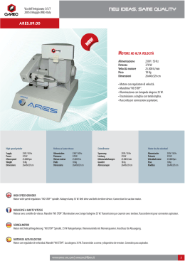
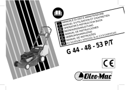
KIT ‘G 6’
FRS / FRT 70 - 85 - 110
FRD 22 - 32 - 33 - 42 - 43
FRN / FRO / FRV 22-23 - 32-33 - 42-43
FXA 100
IEC Ø 14 - Ø 19 - Ø 24 - Ø 28
KG6- Ed.02-2013
Giunto per Motore
- Istruzioni di Montaggio
Motor Coupling
- Assembling Instructions
Motor Kupplung
- Montagesanweisungen
Accouplement pour Moteur
- Instructions d’Assemblage
Acoplamento para Motor
- Instruções de Montagem
Acoplamiento para Motor
- Instrucciones de Montaje
A - Sostituire la linguetta motore con la linguetta corta (6) in
dotazione.
B - Inserire lo spessore (7) e la linguetta (6) sull’albero motore.
C - Inserire vite (3), rondella (4) e dado (5) nel giunto (1); inserire il giunto sull’albero motore fino a battuta dello spessore
(7) e serrare a fondo la vite di fissaggio (3).
D - Ingrassare leggermente i denti ed i vani dell’elemento elastico (2)
E - Inserirlo sul giunto riduttore col lato come indicato (D) .
Allineare verticalmente un dente del giunto motore con un
vano del giunto riduttore. Serrare a fondo le viti di fissaggio
del motore.
A - Replace the motor key with the supplied short key (6) .
B - Fit the spacer (7) and the short key (6) on motor shaft.
C - Fit in screw (3), washer (4) and nut (5) into coupling (1); fit the
coupling (1) on motor shaft until it is in contact with the spacer
(7) and tightly fasten the fixing screw (3).
D - Slightly grease teeth and tooth spaces of the spider (2).
E - Fit it into the gearbox coupling with the side as shown (D).
Align vertically one tooth of motor coupling with one space of
gearbox coupling, close and tighten the motor fixing screws.
A - Remplacer la clavette moteur par la petite clavette fournie (6).
B - Insérer l’épaisseur (7) et la petite clavette (6) sur l’arbre moteur.
C - Insérer la vis (3), rondelle (4) et écrou (5) dans l’accouplement (1);
insérer l’accouplement sur l’arbre moteur jusqu’à butée de l’épaisseur (7) serre à fond la vis de fixation (3).
D - Graisser légèrement les dents et les entredents de l’élément élastique (2).
E - Insérer l’élément élastique (2) sur l’accouplement réducteur avec
côté comme indique (D).
Aligner verticalement un dent de l’accouplement moteur avec un
entredent de l’accouplement réducteur, fermer et serrer à fond les
vis de fixation du moteur.
A - Ersetzen Sie die Passfeder des Motors durch die kurze Passfeder (6) in
Ausstattung.
B - Stecken Sie den Distanzring (7) und die Passfeder (6) auf Motorwelle.
C - Legen Sie, Schraube (3) Scheibe (4) und Mutter (5) in der Kupplung
ein; legen Sie die Kupplung auf Motorwelle bis wann es reicht den
Distanzring ein (7)und ziehen Sie gut die Befestigungsschraube an (3).
D - Fetten Sie leicht die Zähne und Zahnlücken der Kupplungsscheibe (2).
E - Schieben Sie diese mit der Seite wie geeignetes auf die Getriebekupplung (D).
Richten Sie vertikal einen Zahn der Motorkupplung an einem
Zahnraum der Getriebekupplung aus. Ziehen Sie die Motorbefestigungsschrauben fest an.
A - Sustituir la chaveta motor por la chaveta corta (6) que se incluye.
B - Insertar el distanciador (7) y la chaveta corta (6) sobre el eje motor.
C - Insertar tornillo (3), arandela (4) y tuerca (5) en el acoplamiento (1) ;
insertar el acoplamiento sobre el eje hasta que se encuentre en
contacto con el distanciador (7) y apretar a fondo el tornillo de
fijación (3).
D - Engrasar ligeramente los dientes y el espacio entre dientes del
elemento elástico (2).
E - Insertarlo sobre el acoplamiento reductor con el lado como indicado
(D).
Alinear verticalmente un diente del acoplamiento motor con un
espacio entre dientes del acoplamiento reductor, cerrar y apretar a
A - Substituir a chaveta do motor pela chaveta curta fornecida (6).
B - Monte o distanciador (7) e a chaveta (6) no veio do motor.
C - Monte o parafuso (3), anilha (4) e porca (5) no acoplamento (1); aperte
o parafuso no veio do motor até que entra em contacto com o
distanciador (7) e aperte a fundo o parafuso de fixação (3).
D - Lubrifique ligeiramente os dentes e os espaços entre dentes do
elemento elástico (2)
E - Insere no acoplamento redutor com o lado conforme mostrado (D).
Alinhe verticalmente um dente do acoplamento motor com um espaço
do dente do acoplamento redutor, feche e aperte a fundo os parafusos
de fixação do motor.
A
2
1
4
5
3
7
6
B
C
7
6
Numero Spessori (7) / Spacer (7) Number
- Normale / Normal: 1 [3 mm]
- VS (come motore/as motor): No Distanziale (7) / No Spacer (7) WARNING
- IEC90 / B14 (G6 - Ø24 & 534.206.140): 1 + 1 [3+3 mm] WARNING
- RD32 IEC100-112 / B5 (G6 - Ø28 & 563.206.250): 1+1+1 [3+3+3 mm] WARNING
D
1
E
6
- Vano Giunto
- Tooth Space
G6
M [Nm]
Ø 14
Ø 19
Ø 24
Ø 28
15.3 ÷ 18
15.3 ÷ 18
15.3 ÷ 18
15.3 ÷ 18
- Dente Giunto
- Coupling Tooth
6
- Lato marcato “6” da inserire nel riduttore
- Side marked “6” to fit into the gearbox
AVVERTENZA / WARNING
IT In caso di ripetuti avviamenti, inversioni o notevoli vibrazioni
si consiglia l’applicazione di frena filetti Loctite 242 o
Loxeal 55-03 sulla vite (3), oppure la sostituzione del dado
standard con un dado autobloccante.
GB In case of repeated starts/stops or significant vibrations, it is
recommended to apply some thread-locking Loctite 242 or
Loxeal 55-03 liquid sealant on the screw (3), or to replace the
standard nut by a self-locking one.
Scaricare