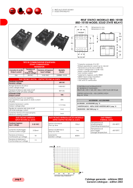
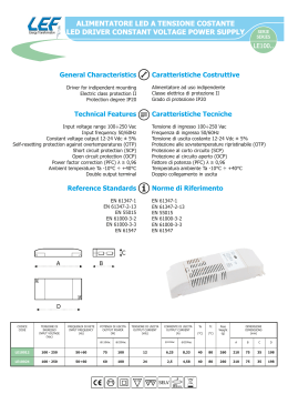
ITALIANO
!
ENGLISH
!
LEGGERE ATTENTAMENTE LE ISTRUZIONI PRIMA DELL’INSTALLAZIONE E CONSERVARE PER FUTURE CONSULTAZIONI.
XV300K è un controllo per la regolazione della velocità di ventilatori AC regolabili in tensione. La caratteristica di regolazione è dipendente dal carico e
dalla tensione di alimentazione. XV300K dispone di 1 ingresso di comando per segnale 0…10V, 4…20mA, pwm, ModBUS-RTU proveniente da controllore
remoto.
INSTALLAZIONE MECCANICA
Per garantire un adeguato smaltimento del calore, il regolatore XV300K deve essere fissato a parete in modo verticale evitando qualsiasi ostacolo al
passaggio dell’aria nella zona del dissipatore. XV300K ha grado di protezione IP55 ma va comunque protetto da liquidi corrosivi, gas, fonti di calore e
posizionato preferibilmente al riparo dai raggi solari. Assicurarsi inoltre che esso non sia soggetto a vibrazioni.
XV308K
XV312K
XV320K
XV328K
XV340K
XV350K
XV360K
Dimensioni (mm)
Peso
(kG)
A
230
230
230
340
340
340
340
2,5
4
4,8
7
9
17
18
Versioni Standard
Grado IP20
Peso
(kG)
XV310K
XV316K
XV320K
XV328K
XV340K
2,5
4
4,8
7
9
B
165
265
265
270
270
440
440
Viti fissaggio (mm)
C
150
165
230
235
235
235
235
D
215
215
215
322
322
322
322
E
80
170
170
165
165
340
340
F
/
/
/
/
/
170
170
Dimensioni (mm)
A
230
230
230
340
340
B
165
265
265
270
270
Ø
M4
M4
M4
M5
M5
M5
M5
Viti fissaggio
C
150
165
165
235
235
D
215
215
215
322
322
E
80
170
170
165
165
Passacavi IP67
(diametro min. - max cavo)
(diametro foro mm)
5-7
7-10
10-14
Ø 17
Ø20,5
Ø 25
2
2
1
1
2
1
1
2
2
1
2
1
2
1
2
1
(mm)
F
/
/
/
/
/
Ø
M4
M4
M4
M5
M5
XV308K
XV310K
XV312K
XV316K
XV320K
XV328K
XV340K
XV350K
XV360K
Corrente
nominale
(A) RMS
8
10
12
16
20
28
40
50
60
Corrente
max*
(A) RMS
12
12
23
23
30
50
70
70
80
Potenza
dissipata
(W)
30
40
60
70
80
120
155
180
250
Cavi Potenza
(mm²) LS(mm)
1,5
1,5
2,5
2,5
2,5/4
6
10
16
16/25
9
9
12
12
12
15
15
Fusibili
Linea
(A)
10
16
16
20
25
35
50
63
80
Passacavi
(diametro foro mm)
Ø 13
Ø16
2
2
2
1
1
Fusibili
Extrarapidi
(A)
16
16
25
25
32
50
63
80
100
Ø 21
1
1
1
2
2
Standard versions
IP55 Grade
Weight
(kG)
XV308K
XV312K
XV320K
XV328K
XV340K
XV350K
XV360K
2,5
4
4,8
7
9
17
18
A
230
230
230
340
340
340
340
Standard versions
IP20 Grade
Weight
(kG)
XV310K
XV316K
XV320K
XV328K
XV340K
2,5
4
4,8
7
9
B
165
265
265
270
270
440
440
Fixed screw (mm)
C
150
165
230
235
235
235
235
D
215
215
215
322
322
322
322
E
80
170
170
165
165
340
340
F
/
/
/
/
/
170
170
Dimensions (mm)
A
230
230
230
340
340
B
165
265
265
270
270
C
150
165
165
235
235
Ø
M4
M4
M4
M5
M5
M5
M5
Cable glands IP67
(diameter min. - max cable)
(diameter hole mm)
5-7
7-10
10-14
Ø 17
Ø20,5
Ø 25
2
2
1
1
2
1
1
2
2
1
2
1
2
1
2
1
-
Fixed screw
(mm)
E
80
170
170
165
165
F
/
/
/
/
/
D
215
215
215
322
322
Ø
M4
M4
M4
M5
M5
Ø 13
2
-
Cable glands IP68
(Metric)
(dia. hole mm)
M32
M40
Ø 32
Ø 40
2
2
2
2
Cable glands
(diameter hole mm)
Ø16
Ø 21
1
2
1
2
1
1
2
1
2
All wiring should conform to local regulations and must be made by authorized personnel only.
To protect the power line and the regulator, the installation technician must install extra-rapid semiconductor fuses upstream of the power supply
adequate for the load and with a value of I²t less than the value given in the table below. If a differential circuit breaker is installed, it must be of the
delayed action type. The data are related to operate at 400V~ 50Hz. For 230V voltage supply or models at 440-460V all current data are the same.
*Max current refers to an environment temperature of 50°C for a maximum time of 10 sec every 5 minutes.
XV308K
XV310K
XV312K
XV316K
XV320K
XV328K
XV340K
XV350K
XV360K
610
610
720
720
720
8000
15000
15000
80000
Dimensions (mm)
ELECTRICAL INSTALLATION
Max energia I²xt
(A²S)
Max
Power
(kVA)
5,5
6,5
8
11
13
19
26
32
41
Nominal
Current
(A) RMS
8
10
12
16
20
28
40
50
60
Max*
Current
(A) RMS
12
12
23
23
30
50
70
70
80
Power
dissipation
(W)
30
40
60
70
80
120
155
180
250
Power Cables
(mm²) LS(mm)
1,5
1,5
2,5
2,5
2,5/4
6
10
16
16/25
9
9
12
12
12
15
15
Line
Fuses
(A)
10/16
16
16/20
20
25
35
50
63
80
Extrarapid
Fuses
(A)
16
16
25
25
32
50
63
80
100
Max energy I²xt
(A²S)
610
610
720
720
720
8000
15000
15000
80000
LS = electrical wire peeling length (mm)
LS=lunghezza di spellatura cavo (mm).
Per collegare i fili ai morsetti a molla, fare leva con un cacciavite sulla leva o sul foro rettangolare (vedi + avanti la vista panoramica schede) per aprire il
terminale. I cavi di potenza dei regolatori XV350K e XV360K devono essere crimpati per formare un occhiello (foro M6 ) e serrati con una chiave (E10).
Collegare i conduttori di alimentazione e di terra agli appositi morsetti del regolatore. Per evitare correnti di dispersione, la terra del motore deve essere
collegata all’apposito morsetto di terra del motore. Si consiglia di non introdurre alcun dispositivo elettromeccanico sul cavo del motore e di collegare
sempre al circuito di sicurezza della macchina gli eventuali protettori termici dei motori per togliere l’alimentazione al controllo e salvaguardare con la
massima efficacia il motore. Se la lunghezza del cavo del motore supera i 10 metri si consiglia di usare cavo schermato. Il carico del controllo può essere
costituito da più motori purchè la somma delle correnti nominali dei motori sia inferiore del 20% della corrente nominale del controllo. Se la lunghezza dei
cavi dei comandi supera i 3 metri si consiglia di usare cavo schermato, collegando lo schermo solo dalla parte del regolatore. Consigliamo di non
collegare lo 0 Volt dei comandi con la terra. Qualora il percorso dei cavi di alimentazione, motore e comandi sia superiore a 10 metri, fare in modo che
questi si distanzino tra loro di almeno 0,3 metri per evitare che si crei un effetto di accoppiamento. Per applicazioni su ambienti con presenza di
significative sorgenti di campo elettromagnetico, si consiglia di inserire il controllo all’interno di un vano metallico idoneo. Al fine di contrastare la
formazione di condensa, e il buon funzionamento anche a temperature rigide è consigliabile assicurare un’alimentazione costante. Temperatura di
funzionamento -25T50, temperatura di stoccaggio -40T80.
Tutti i cavi di collegamenti devono resistere ad una temperatura di lavoro di 80°C.
Evitare di far passare qualsiasi filo vicino alle bobine di rame del filtro, servirsi dell’apposito sostegno di plastica! Serrare bene i fili sulle
morsettiere di comando e di potenza evitando la fuoriuscita dei trefoli.
Durante le prove di isolamento dell’equipaggiamento elettrico, scollegare le linee di ingresso e di uscita di potenza del regolatore. Usare un
tester a vero valore efficace (RMS) per misurare valori di corrente o tensione.
Per la direttiva bassa tensione è stata scelta come riferimento la norma EN60730-1 . Per la direttiva compatibilità elettromagnetica, è stata scelta come
riferimento la norma per gli azionamenti elettrici a velocità variabile EN 61800-3. In riferimento ad alcune applicazioni tipiche di utilizzo, i regolatori
XV308/312/320K sono idonei agli ambienti residenziale e commerciale, mentre i regolatori XV328/340..360K sono idonei all’ambiente industriale. Si
ribadisce che i controlli XV300K sono progettati per essere incorporati su macchine o integrati su quadri elettrici e quindi sono da considerarsi componenti.
Si fa carico all’installatore di seguire i criteri di compatibilità contenuti in questo manuale e di garantire la conformità alle direttive.
SICUREZZA
Classificazione elettrica: Classe II per gli ingressi di comando (4kV di isolamento con le parti in tensione), Classe I rispetto le parti accessibili. Protezione
per sovratensioni Cat. II.
Protezioni elet.: Mancanza fase di alimentazione, surriscaldamento interno del regolatore.
ATTENZIONE: Il regolatore si ripristina automaticamente. Per evitare scariche elettriche o danneggiamenti alle attrezzature deve essere
prestata la massima attenzione quando viene rimosso il coperchio per tarature o controlli (solo personale autorizzato). In tutti gli altri casi in
cui viene rimosso il coperchio la tensione deve essere tolta. XV300K è previsto per il controllo di apparecchiature in condizioni operative
normali. Nei casi in cui un guasto o un errato funzionamento del XV300K potesse portare a una condizione operativa anomala in grado di
provocare lesioni alle persone o danni all’apparecchiatura e ad altro, è necessario incorporare dispositivi (limitatori o comandi di sicurezza) o
sistemi (sistemi di allarme o di supervisione) aggiuntivi destinati a dare segnalazione o protezione in caso di guasto o errato funzionamento
del XV300K e questi devono essere mantenuti come parte del sistema di controllo.
SMALTIMENTO
Il simbolo presente sull’apparecchiatura indica che essa non deve essere considerata un normale rifiuto domestico, pertanto deve essere trasferito nei
punti di raccolta adatti per il riciclaggio di apparecchiature elettriche ed elettroniche.
1569000850 XV300K r.3.0 12.11.2014
MECHANICAL INSTALLATION
The XV300K regulator must be wall-mounted vertically, in order to guarantee adequate dispersion of heat in the area of air circulation and prevent
obstructions to air flow in the dissipater zone. XV300K has IP55 grade protection, anyway protect it from corrosive liquids, gas, heat sources and position
it preferably sheltered from the sun's rays. Make sure that it does not undergo vibrations.
Pressacavi IP68
(Metrici)
(dia. foro mm)
M32
M40
Ø 32
Ø 40
2
2
2
2
INSTALLAZIONE ELETTRICA
Il cablaggio deve essere conforme alle normative locali ed essere eseguito esclusivamente da personale autorizzato. Per proteggere la linea e il
regolatore, l’installatore deve prevedere a monte dell’alimentazione del regolatore dei fusibili di tipo extrarapido per semiconduttori adeguati al carico
effettivo e con un valore di I²xt inferiore al valore riportato nella tabella sottostante. L’eventuale protezione con interruttore automatico-differenziale deve
prevedere un differenziale di tipo ritardato. I dati indicati sono relativi ad un funzionamento a 400V~. Per il funzionamento a 230V~ o modelli a 440/460V~
fanno fede gli stessi dati di corrente.
*La corrente massima è riferita alla temperatura massima ambiente di 50°C per un tempo massimo di 10 secondi ogni 5 minuti.
Potenza
massima
(kVA)
5,5
6,5
8
11
13
19
26
32
41
XV300K is a controller for the speed of AC fans with adjustable voltage. The controller characteristic is affected by the load and supply voltage. XV300K
is fitted with 1 control input for 0…10V, 4…20mA signal, pwm signal, ModBUS-RTU signal delivered from a remote control.
CODING
XV3_ _K – 70C20 C : 0= IP20, 1= IP55
CODIFICA
XV3_ _K – 70C20 C : 0= IP20, 1= IP55
Versioni Standard
Grado IP55
READ THIS INSTRUCTION SHEET CAREFULLY BEFORE INSTALLING, RETAIN IT SAFELY FOR FUTURE REFERENCE.
To connect wiring to the spring terminals, apply leverage with a screwdriver on the lever or on the rectangular hole to open the terminal (see below the
panoramic view cards). The power wires of the XV350K and XV360K regulators must be crimped to form an eyelet (M6 hole) and the nuts (E10)
tightened with a wrench.
Connect the power wires and ground to the appropriate regulator terminals. To avoid dispersion currents, the motor earth cable must be connected to
the appropriate motor terminal ground. We recommend connecting to the machine’s safety circuit any thermal motor protector in order to remove the
control power supply and protect the motor with maximum efficiency. If the length of the motor cable exceeds 10 metres, we suggest using shielded
cable. The control load can consist of several engines provided the sum of the rated currents of the motors is less than 20% of the rated current of the
control. We recommend not introduce any electromechanical device on the motor cable. If the control cable length exceeds 3 metres, we suggest you to
use shielded cable, connecting the shield only on the regulator. We suggest don’t connect the control 0volt to the earth. If the length of the power, motor
and control cables exceeds 10m, make sure they are separated by at least 0.3 metres to avoid creating a coupling effect. If controls are set up in
environment subject to electromagnetic disturbance, they should be housed inside a suitable metallic enclosure. In order to prevent the formation of
condensation and regular working also cold temperature it is recommended you insure a constant power supply, avoiding turning it off continually.
Operating temperature -25T50, storing temperature -40T80.
All connections wires must resist to 80°C working temperature.
Avoid routing any electric wires near the copper coils of the filter, use the suitable plastic support! Tighten all wires on control and power
terminal boards fully down, avoiding protrusion of the multi-stranded wire.
During voltage insulation tests disconnect the regulator power lines In/Out. Use a true (RMS) tester to measure the current or
voltage value.
According to safety directive, reference standard EN60730-1. According to EMC, reference standard EN 61800-3. With refer to some typical
applications, the XV308/312/320K regulators are suitable for residential and commercial ambient, while the XV328/340..360K regulators are suitable for
industrial ambient. XV300K regulators are designed to be installed inside a machine or a standard electrical cabinet and are therefore considered a
component. The installer must guarantee that the machine conforms to such regulations.
SECURITY
Class II at the command inputs (insulation of 4kV between commands block and the device supplied parts). Class I as regards the accessible parts.
Protection against power surges Class II.
Elec. Protections: Phase lost, inside overheating.
CAUTION: the regulator restores automatically.
To prevent electrical shock or damage to equipment, the utmost care should be taken when the cover is removed (by authorized personnel
only) for adjustments or checks. In all other cases when the cover is removed, the power should be switched off. The XV300K is designed
to control equipment under normal operating conditions. Where failure or malfunction of the XV300K could lead to an abnormal operating
condition that could cause personal injury or damage to the equipment or other property, other devices (limiters or safety controls) or
systems (alarm or supervision systems) intended to warn of or protect against failure or malfunction of the XV300K must be incorporated
and maintained as part of the control system.
DISPOSAL
The sign marked on the equipment indicates that it is not to be considered as a normal domestic waste; therefore it has to be disposed of in a specific
electrical and electronic equipment recycling point.
XV300K
1/2
XV308/310K vista scheda – view card
XV312/316/320K vista scheda – view card
XV328/340/350/360K vista scheda – view card
Cambio tensione
Change voltage
6 = 230/400V
7 = 400V
8 = 440/460V
230
/
440
400
400
460
ITALIANO
ENGLISH
MORSETTIERA DEI COMANDI
T1 +
T1 0V
0.10
+V
NC
COM
NO
+5V
IN 1
0V
4.20
CONTROLS TERMINAL BOARD
Descrizione
Applicazione
Seriale RS485, ModBUS RTU - slave
Seriale RS485, ModBUS RTU - slave
Massa I/O
Ingresso analogico, tipo 0..10V (Ri = 40 kΩ)
Uscita alimentazione 12V= (max 30mA)
Uscita contatto norm. chiuso relè 1
Uscita contatto comune relè 1
(1A-250V~/3A-30V=)
Uscita contatto norm. aperto relè 1
Uscita alimentazione 5V= (max 15mA)
Ingresso pwm (5..15V, frequenza 100Hz)
Massa I/O
Ingresso analogico, tipo 4…20mA (Ri = 100 Ω)
Linea di collegamento seriale da un dispositivo che comanda come
Master
T1 +
T1 0V
0.10
+V
NC
Massa I/O
Ingresso di comando 0..10V
Alim. Potenziometro esterno per comando manuale
Uscita programmabile. Nella tipica configurazione per Difetto, il relè è
eccitato (NO-COM chiusi tra loro) e si diseccita se avviene
un’emergenza.
COM
NO
+5V
IN 1
0V
4.20
/
Ingresso di comando pwm a valore medio variabile
Massa per ingresso analogico
Ingresso di comando 4..20mA
Description
Application
Serial RS485, ModBUS RTU - slave
Serial RS485, ModBUS RTU - slave
Ground I/O
Analogue input, tipo 0..10V (Ri = 40 kΩ)
Aux. supply output 12V= (max 30mA)
Relay 1 contact output norm. closed
Relay 1 common contact output
(1A-250V~/3A-30V=)
Relay 1 contact output norm. open
Output aux. supply 5V= (max 15mA)
Analogue input pwm (5..15V, 100Hz frequency)
Ground I/O
Analog input , type 4…20mA (Ri = 100 Ω)
Serial connection line to a Master controlled device
Ground I/O
0..10V analogue command input
External potentiometer supply for manual command
Programmable output. With standard setting for Defect, the relay is
enabled (NO-COM each other closed) and is disabled in emergency
case.
/
Pwm input command with variable average value
Ground for analogue inputs
4..20mA analogue command input
SEGNALAZIONI LED
DL1 : giallo, inizia a lampeggiare al valore minimo del segnale di ingresso aumentando la sua frequenza man mano che aumenta il segnale fino a restare
acceso per segnale = 100%. Segue il segnale prioritario (vedi Impo. Base [IB] nel menù Parametri di Fabbrica).
DL2 : verde, acceso = presenza alimentazione.
DL3 : rosso, presenza allarme: 1 lampeggio = mancanza fase di alimentazione; 3 lampeggi = sovratemperatura interna; 5 lampeggi = Stop per
programmazione parametri;
DL4 : verde, lampeggia in trasmissione ModBUS.
DL5 : rosso, lampeggia in ricezione ModBUS.
LEDS WARNING SIGNALS
DL1 : yellow, starts to flash with input signal at minimum and increases the flashing frequency as the signal rises. It goes on steady with signal = 100%.
It follows the priority signal (see Basic Sett. [BS] in the Factory Parameters menu).
DL2 : green, steady ON = power supply ON.
DL3 : red, warning alarm ON: 1 flash = power phase lost; 2 flashes = external emergency; 3 flashes = internal over-temperature.
5 flashes = stop for parameters programming or error settings.
DL4 : green, flashing in ModBUS transmission.
DL5 : red, flashing in ModBUS reception.
INDIRIZZI ModBUS PRINCIPALI (Documentazione dettagliata su richiesta)
S* scrittura possible solo se il parametro “Blocco regolazione” è impostato a 1
S** reboot neccessario dopo la scrittura
ModBUS ADDRESS (Details available upon request)
S * Writing possible only if the parameter "Adjustment Lock" is set to 1
S ** necessary reboot after writing the changes
Indirizzo
HEX
Variabile
Unità
Lettura /
Scrittura
Valore
Min.
Valore
Max.
Descrizione
HEX
Address
0x00B
Uscita di
tensione
%
L
-
-
indica la percentuale di tensione erogata al motore
0x00D
Allarme
Num
L
-
-
Num
L/S
0
1
Num
L/S**
1
247
indica l'indirizzo ModBUS (slave) - default 0x01
0x421
3
(=1 se 9600bps); (=2 se 19200); (=3se 38400) - default
=2
0x422
Baudrate
0x423
Stop Bit
0x400
0x421
0x422
0x423
Blocco
regolazione
Indirizzo del
regolatore
Baudrate
Bit di stop
Num
Num
L/S**
L/S**
1
1
2
0x424
Parità
Num
L/S**
1
3
0x425
Timeout
sec
L/S*
1
240
0x401
0x402
0x403
0x404
0x405
Comando via
ModBUS
Ingresso min
Ingresso max
Tensione min.
V1
Tensione max.
V2
%
%
L/S*
L/S*
%
L/S*
%
L/S*
%
L/S*
0
10
Ingresso
minimo
Lim.Min.
Motore
Tensione
min. V1
100
Ingresso max
0=nessun errore; 1=mancanza fase; 3=Temp interna;
5=impostazioni errate; 6=timeout MDB
scrivere il valore 1 per abilitare la scrittura
Scrivere il valore 0 per riabilitare la regolazione
(=1 se nessuna parità); (=2 per parità pari); (=3 per
parità dispari) - default =1
indica il tempo entro il quale il master deve rinnovare il
comando di regolazione
variabile che permette la regolazione (0-100) tramite
ModBUS.
Segnale di comando tensione/velocita V1.
Tensione/velocita relativa al punto di segnale di
comando IN.MINIMO.
Tensione/velocita relativa al punto di segnale comando
IN.MASSIMO.
( =2 per resettare e caricare i valori di default del
regolatore) (=3 per riavviare dopo modifica parametri
dove è richiesto reboot)
Tensione che sostituisce V1, in modo Slave , quando
LIMITE V1>V1.
1
3
0x40A
Lim. Velocità V1
%
L/S*
Lim Min.
Motore
Limite V2
0x411
Kick start
Num
L/S*
0
1
(=0 kick start disattivo)(=1 kick start attivo)
0x41E
Profilo di
regolazione
Num
L/S*
1
2
(=1 curva lineare) (=2 curva per ventilatori assiali)
Max.
Value
0x00B
Voltage
output
%
L
-
-
0x00D
Allarm
Num
L
-
-
Num
L/S
0
1
Num
L/S**
1
247
Indicates the ModBUS address (slave) - default 0x01
Num
L/S**
1
3
(=1 if 9600bps); (=2 if 19200); (=3 if 38400) - default =2
Num
L/S**
1
2
(=1 if 1 stop bit); (=2 if 2 stop bit) - default=1
Num
L/S**
1
3
sec
L/S*
1
240
%
L/S*
0
100
%
L/S*
10
Max input
(=1 if no parity); (=2 if even parity); (=3 if odd parity) default =1
Indicates the time within which
the master must renew his command regulation
variable for command the regulation (0-100) by
ModBUS
Voltage signal command/speed V1
%
L/S*
Min. input
100
Voltage signal command/speed V2
Lim.Min.
Motor
Min. V1
Voltage
Max. V2
Voltage
Lim. Max.
Motor
Esempio: Richiesta del MASTER di lettura della variabile “uscita di tensione” identificato con indirizzo 0x0B: 01 03 00 0B 00 01
Richiesta del MASTER di scrittura sulla variabile “ingresso di comando ModBUS” identificato con indirizzo 0x401: 01 06 04 01 00 01
Attenzione: Il comando di regolazione tramite modBUS necessita di riscrittura nel relativo indirizzo entro il tempo di time out (default 30 secondi) anche se
il valore rimane invariato. Scaduto il timeout, in mancanza di qualsiasi altro segnale di comando, il dispositivo interromperà la regolazione spegnendo le
uscite di potenza.
Stop
regulation
Regulator
address
Parity
Timeout
0x402
Command
by ModBUS
Min. input
0x403
Max input
0x401
Tensione max.
V2
Lim. Max.
Motore
L/S*
Min.
Value
0x425
Segnale di comando tensione/velocita V2.
Num
Reading /
Writing
0x424
100
Reset
Unit
0x400
(=1 se 1 di stop); (=2 se 2 bit di stop) - default=1
0x407
Variable
0x404
0x405
Min. V1
Voltage
Max. V2
Voltage
%
L/S*
%
L/S*
Description
Indicates the output percentage voltage/speed.
0=no error; 1=phase lost; 3=over temperature;
5=incorrect settings; 6=timeout MDB
Write the value 1 to enable writing and disable the
running. Place to 0 to re-enable the running.
Voltage/speed of IN.MIN. command signal point
Voltage/speed of IN.MAX. command signal point
0x407
Reset
Num
L/S*
1
3
(=2 to reset and load the controller’s default values) (=3
to restart the regulator after changing the parameter/s
when is required the reboot)
0x40A
Lim. Spped
V1
%
L/S*
Lim.Min.
Motor
V2 Limit
Voltage that replaces V1, when V1 LIMIT>V1.
0x411
Kick start
Num
L/S*
0
1
(=0 kick start enable)(=1 kick start able)
0x41E
Regulation
profile
Num
L/S*
1
2
(=1 linear profile) (=2 axial fans profile)
Example: Request by the MASTER to read the variable "output voltage" identified with address 0x0B: 01 03 00 0B 00 01
Request by the MASTER to write on the variable “ModBUS input command” identified with address 0x401: 01 06 04 01 00 01
Caution: The regulation command via ModBUS requires rewriting in its address within the time out (default 30 seconds) even if the value remains
unchanged. Over the time out, and in absence of any other command signal, the regulator will switch off the power outputs.
Made for DIXELL S.r.l. by FAE Fagan – ITALY
1569000850 XV300K r.3.0 12.11.2014
XV300K
2/2
Scarica