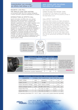
RH158 DC-motor with gearbox
Motor data
Motor order number
Type
130-10-12-0015
130-10-12-0030
130-10-12-0075
130-10-12-0100
130-10-12-0200
130-10-12-0250
130-10-12-0510
130-10-12-0630
130-10-24-0015
130-10-24-0030
130-10-24-0075
130-10-24-0100
130-10-24-0200
130-10-24-0250
130-10-24-0510
130-10-24-0630
RH158-12-15
RH158-12-30
RH158-12-75
RH158-12-100
RH158-12-200
RH158-12-250
RH158-12-510
RH158-12-630
RH158-24-15
RH158-24-30
RH158-24-75
RH158-24-100
RH158-24-200
RH158-24-250
RH158-24-510
RH158-24-630
Nominal
voltage
(V)
12
12
12
12
12
12
12
12
24
24
24
24
24
24
24
24
Current at
max. torque
(mA)
660
660
680
680
580
500
300
270
330
330
340
340
290
250
150
135
Ratio
15:1
30:1
75:1
100:1
200:1
250:1
510:1
630:1
15:1
30:1
75:1
100:1
200:1
250:1
510:1
630:1
Maximum
torque
(mNm)
100
200
500
600
1000
1000
1000
1000
100
200
500
600
1000
1000
1000
1000
General data
Spark suppression
Maximum radial shaft load
Maximum axial shaft load
Mass of motor
Temperature range
Dimensional drawing
A88/Rev.0
50 N
10 N
190 grams
-200C to +600C
Speed at
no load
(rpm)
440
210
81
66
33
26
12
10
440
210
81
66
33
26
12
10
Speed at
max. torque
(rpm)
300
140
55
45
23
21
10,5
9
300
140
55
45
23
21
10,5
9
Diameter Length
(mm)
(mm)
40/30
40/30
40/30
40/30
40/30
40/30
40/30
40/30
40/30
40/30
40/30
40/30
40/30
40/30
40/30
40/30
64
64
66,5
66,5
69
69
72
72
64
64
66,5
66,5
69
69
72
72
M o t o r i d u t t o r i
G e a r - m o t o r s
S e r i e s
R H
1 5 8
Peso approssimativo: 190g
Direction of rotation depending on polarity
Can be mounted in any position
Maximum radial shaft load: 50N
Maximum axial shaft load: 10N
Temperature range: -20°C/60°C
Approx weight: 190g
Valori tipici a temperatura ambiente +20°
Typical values at ambient temperature +20°
Direzione di rotazione secondo polarità
Può essere montato in ogni posizione
Massimo carico radiale: 50N
Massimo carico assiale: 10N
Temperatura di esercizio: -20°C/60°C
TENSIONE
NOMINALE
TIPO
TYPE
RAPPORTO
:1
L
NOMI NAL
VOLTAGE
VELOCITA'
SPEED
COPPIA
MASSIMA
SENZA
CARICO
NO LOAD
MAXIMUM
TORQUE
RATIO
TO :1
CORRENTE
CURRENT
CON MAX
COPPIA
AT MAX
TORQUE
rpm
V
mm
12
15
24
12
24
64
14,14
10
440
300
12
30
24
12
RH 158
75
24
12
24
12
24
64
29,75
20
210
140
66,5
76,84
50
81
55
12
100
24
12
RH 158
200
24
12
24
66,5
94,37
60
66
45
12
24
69
198,5
100
33
23
12
250
24
12
24
69
243,8
100
26
21
12
510
24
12
RH 158
630
24
12
24
12
24
72
512,85
100
12
10,5
72
629,82
100
10
9
RH 158
RH 158
RH 158
RH 158
RH 158
8
2,5
Ncm
5,5
L
17,5
CON MAX
COPPIA
AT MAX
TORQUE
SENZA
CARI CO
NO LOAD
mA
<140
<70
660
330
<140
<70
<140
<70
<140
<70
660
330
680
340
680
340
<140
<70
580
290
<140
<70
<140
<70
<140
<70
500
250
300
150
270
135
15
14
27
2,5
M3(x3
Ø39,6
Ø12
5,5
Ø30
7
120
°
31
Ø36,6
Ø2,3
45
°
Ø6h8
max
4
mm
s.r.l
Viale Piave, 80/82 - 23879 VERDERIO INF. (LC) ITALY
Tel. 039510611-499 Fax 039513617
www. micromotorssrl.com e-mail: [email protected]
MOTORIDUTTORI CON ENCODER AD EFFETTO HALL
GEAR-MOTORS WITH HALL-EFFECT ENCODER
M
Collegamenti:
+
3
2
1
-
Rosso
Blu
Verde
Marrone
Nero
:
:
:
:
:
+Motore
O.C. Output
GND
Vcc (Hall)
-Motore
Connections:
+
3
2
1
-
H
A
L
L
:
:
:
:
:
Red
Blue
Green
Brown
Black
+Motor
O.C. Output
Ground
Vcc (Hall)
-Motor
+ 3 2 1 -
Magnete a sei poli:
tre impulsi ogni giro motore
Six poles magnet:
three pulses for motor turn
Interruttori ad effetto Hall
Questi interruttori ad effetto Hall, sono sensori
altamente stabili termicamente e resistenti alle
sollecitazioni meccaniche, sono maggiormente
utilizzati in applicazioni dove il campo magnetico
varia rapidamente e il valore di campo residuo è
basso.
Ciascun dispositivo include un regolatore di
tensione, un generatore di Hall, un circuito
stabilizzatore di temperatura, un amplificatore di
segnale, un comparatore di Schmitt ed un transistor
collettore aperto, compresi su di un solo “chip” di
silicio.
Il regolatore di tensione permette di alimentare
il dispositivo con tensione compresa tra 4,5 e 20V.
Il transistor di uscita può sopportare correnti di
20mA massimo. Con opportuno valore di resistenza
di carico in uscita può essere agevolmente
interfacciato con logiche bipolare o MOS.
Hall-effect switches
These Hall-effect switches are highly temperature
stable and stress-resistant sensors best utilized
in applications that provide steep magnetic slopes
and low residual levels of magnetic flux density.
Each device includes a voltage regulator,
quadratic Hall voltage generator, temperature
stability circuit, signal amplifier, Schmitt trigger
and open collector output on a single silicon chip.
The on-board regulator permits operation with
supply voltages of 4,5 to 20 V.
The switch output can sink up to 20 mA. with
suitable output pull up, they can be used directly
with bipolar or MOS logic circuits.
Caratteristiche elettriche a+25°C, Vcc=4,5÷20V (ove non altrimenti indicato)
Electrical characteristics at+25°C, Vcc=4,5 to 20 V (unless otherwise stated)
CARATTERISTICHE
CHARACTERISTICS
CONDIZIONI DI MISURA
TEST CONDITIONS
Tensione di alimentazione
Supply Voltage
Operativa
Operating
Tensione di saturazione d’uscita
Output Saturation Voltage
Corrente di dispersione d’uscita
Output Leakage Current
Corrente di alimentazione
Supply Current
MIN
TIPICO
TYP. MAX
UNITA’
UNITS
4,5
-
20
V
lOUT=20mA, B>BOP
-
150
400
mV
VOUT=20V, B>BRP
-
<1,0
10
µA
-
4,7
8,0
mA
Vcc=4,5V
Uscita aperta
Output open
Tempo di salita dell’uscita
Output Rise Time
Vcc=12V, RL=820Ω, CL=20pF
-
0,04
2,0
µS
Tempo di discesa dell’uscita
Output Fall Time
Vcc=12V, RL=820Ω, CL=20pF
-
0,18
2,0
µS
s.r.l.
Viale Piave, 80/82 - 23879 VERDERIO INF. (LC) ITALY
Tel. 039510611-499 Fax 039513617
www. micromotorssrl.com e-mail: [email protected]
Data Sheet
27631.2C
3132 AND
3133
ULTRA-SENSITIVE BIPOLAR
HALL-EFFECT SWITCHES
X
These Hall-effect switches are designed for magnetic actuation using
a bipolar magnetic field, i.e., a north-south alternating field. They
combine extreme magnetic sensitivity with excellent stability over
varying temperature and supply voltage. The high sensitivity permits
their use with multi-pole ring magnets over relatively large distances.
2
3
OUTPUT
1
GROUND
CC
SUPPLY
V
Each device includes a voltage regulator, quadratic Hall voltage
generator, temperature stability circuit, signal amplifier, Schmitt trigger,
and open-collector output on a single silicon chip. The on-board regulator permits operation with supply voltages of 4.5 to 24 V. The switch
output can sink up to 25 mA. With suitable output pull up, they can be
used directly with bipolar or MOS logic circuits.
The three package styles available provide a magnetically optimized
package for most applications. Suffix ‘LT’ is a miniature SOT89/TO243AA transistor package for surface-mount applications; suffix ‘UA’
features wire leads for through-hole mounting. Prefix ‘UGN’ devices
are rated for continuous operation over the temperature range of -20°C to
+85°C, prefix ‘UGS’ devices over an extended range of -40°C to
+125°C, and prefix ‘UGL’ devices over the range of -40°C to +150°C.
FEATURES
Dwg. PH-003A
Pinning is shown viewed from branded side.
■ 4.5 V to 24 V Operation
■ Reverse Battery Protection
■ Superior Temperature Stability
■ Superior Supply Voltage Stability
ABSOLUTE MAXIMUM RATINGS
Supply Voltage, VCC . . . . . . . . . . . . . 25 V
Reverse Battery Voltage, VRCC . . . . -35 V
Magnetic Flux Density, B . . . . Unlimited
Output OFF Voltage, VOUT . . . . . . . . 25 V
Continuous Output Current, IOUT . 25 mA
Operating Temperature Range, TA
Prefix UGL . . . . . . . -40°C to +150°C
Prefix UGN . . . . . . . . -20°C to +85°C
Prefix UGS . . . . . . . -40°C to +125°C
Storage Temperature Range,
TS . . . . . . . . . . . . . . . -65°C to +150°C
■ Activate with Multi-Pole Ring Magnets
■ Solid-State Reliability
■ Small Size
■ Constant Output Amplitude
■ Resistant to Physical Stress
Always order by complete part number
including prefix and suffix, e.g., UGN3132LT .
3132 AND 3133
BIPOLAR
HALL-EFFECT SWITCHES
FUNCTIONAL BLOCK DIAGRAM
1
VCC
REG.
X
3
OUTPUT
2
GROUND
Dwg. FH-005-2
ELECTRICAL CHARACTERISTICS at TA = +25°C
Limits
Characteristic
Symbol
Supply Voltage
VCC
Min.
Typ.
Max.
Units
Operating
4.5
—
24
V
VOUT(SAT)
IOUT = 20 mA, B ≥ BOP
—
145
400
mV
Output Leakage Current
IOFF
VOUT = 24 V, B ≤ BRP
—
<1.0
10
µA
Supply Current
ICC
VCC = 24 V, B ≤ BRP
—
4.3
9.0
mA
Output Saturation Voltage
Test Conditions
Output Rise Time
tr
VCC = 12 V, RL = 820 Ω, CL = 20 pF
—
0.04
2.0
µs
Output Fall Time
tf
VCC = 12 V, RL = 820 Ω, CL = 20 pF
—
0.18
2.0
µs
MAGNETIC CHARACTERISTICS over operating temperature and voltage range.
Limits
Characteristic
Symbol
Operate Point
BOP
Release Point
Hysteresis
BRP
Bhys
Device Type*
Min.
Typ.
Max.
Units
3132
—
32
95
G
3133
—
32
75
G
3132
-95
-20
—
G
3133
-75
-20
—
G
Both
30
52
—
G
NOTE: As used here, negative flux densities are defined as less than zero (algebraic convention.)
Typical values are at TA = +25°C and VCC = 12 V.
1 gauss (G) is exactly equal to 0.1 millitesla (mT).
*
Complete part number includes a prefix denoting operating temperature range (UGL, UGN, or UGS)
and a suffix denoting package type (LT or UA).
115 Northeast Cutoff, Box 15036
Worcester, Massachusetts 01615-0036 (508) 853-5000
Copyright © 1996, 2003 Allegro MicroSystems, Inc.
3132 AND 3133
BIPOLAR
HALL-EFFECT SWITCHES
TYPICAL CHARACTERISTICS
40
40
OPERATE POINT
OPERATE POINT
20
SWITCH POINT IN GAUSS
SWITCH POINT IN GAUSS
20
VCC = 12 V
0
I OUT = 20 mA
RELEASE POINT
-20
T A = 25°C
0
I OUT = 20 mA
-20
RELEASE POINT
-40
-50
-25
0
25
50
75
AMBIENT TEMPERATURE IN ° C
-40
4.0
125
100
8.0
12
16
SUPPLY VOLTAGE IN VOLTS
Dwg. GH-022
Dwg. GH-021
6.0
200
I OUT = 20 mA
VCC = 12 V
SUPPLY CURRENT IN mA
SATURATION VOLTAGE IN mV
B ≥ B OP
175
150
5.0
4.0
B ≤ B RP
125
100
-50
28
24
20
-25
0
25
50
75
100
125
-25
0
25
50
75
AMBIENT TEMPERATURE IN ° C
AMBIENT TEMPERATURE IN ° C
Dwg. GH-024
Powering up in the absence of a magnetic field (less than
BOP and higher than BRP) will allow an indeterminate output
state. The correct state is warranted after the first excursion
beyond BOP or BRP.
www.allegromicro.com
3.0
-50
100
125
Dwg. GH-023
Bipolar switches may switch on removal of field but
require field reversal for reliable operation over temperature
range; latches will not switch on removal of magnetic field.
3132 AND 3133
BIPOLAR
HALL-EFFECT SWITCHES
SENSOR LOCATIONS
(±0.005” [0.13mm] die placement)
SUFFIX “LT”
ACTIVE AREA DEPTH
0.0305"
0.775 mm
NOM
0.089"
2.26 mm
0.043"
1.09 mm
A
1
2
3
Dwg. MH-008-2D
SUFFIX “UA”
ACTIVE AREA DEPTH
0.0195"
0.50 mm
NOM
0.082"
2.07 mm
0.055"
1.39 mm
A
BRANDED
SURFACE
The products described herein are manufactured under one or
more of the following U.S. patents: 5,045,920; 5,264,783; 5,442,283;
5,389,889; 5,581,179; 5,517,112; 5,619,137; 5,621,319; 5,650,719;
5,686,894; 5,694,038; 5,729,130; 5,917,320; and other patents
pending.
1
2
3
Allegro MicroSystems, Inc. reserves the right to make, from time to
time, such departures from the detail specifications as may be
required to permit improvements in the performance, reliability, or
manufacturability of its products. Before placing an order, the user is
cautioned to verify that the information being relied upon is current.
Allegro products are not authorized for use as critical components
in life-support appliances, devices, or systems without express written
approval.
The information included herein is believed to be accurate and
reliable. However, Allegro MicroSystems, Inc. assumes no responsibility for its use; nor for any infringements of patents or other rights of
third parties that may result from its use.
Dwg. MH-011-10A
Allegro
115 Northeast Cutoff, Box 15036
Worcester, Massachusetts 01615-0036 (508) 853-5000
3132 AND 3133
BIPOLAR
HALL-EFFECT SWITCHES
PACKAGE DESIGNATOR ‘LT’
(SOT89/TO-243AA)
Dimensions in Inches
(for reference only)
0.181
0.173
0.072
0.064
0.167
0.155
1
2
0.063
0.055
0.102
0.090
3
Dimensions in Millimeters
(controlling dimensions)
0.0173
0.0138
0.090
0.084
4.25
3.94
0.0189
0.0142
0.0221
0.0173
0.047
0.035
0.059
4.60
4.40
1.83
1.62
3.00
BSC
Dwg. MA-009-3A in
Dwg. MA-009-3A mm
2.5
2.0
0.098
0.079
B
B
0.031
0.102
A
0.8
2.6
A
4.6
0.181
1
2
2.29
2.13
0.56
0.44
1.50
0.118
BSC
2.60
2.29
3
0.44
0.35
0.48
0.36
1.20
0.89
BSC
BSC
2
1
1.60
1.40
3 0.047
1
2
3
1.2
0.028
0.031
0.7
0.8
TYP
TYP
TYP
TYP
Pads 1, 2, 3, and A — Standard SOT89 Layout
Pads 1, 2, 3, and B — Low-Stress Version
Pads 1, 2, and 3 only — Lowest Stress, But Not Self Aligning
Pads 1, 2, 3, and A — Standard SOT89 Layout
Pads 1, 2, 3, and B — Low-Stress Version
Pads 1, 2, and 3 only — Lowest Stress, But Not Self Aligning
Dwg. MA-012-3 in
Dwg. MA-012-3 mm
NOTES: 1. Exact body and lead configuration at vendor’s option within limits shown.
2. Supplied in bulk pack (500 pieces per bag) or add "TR" to part number for tape and reel.
3. Only low-temperature (≤240°C) reflow-soldering techniques are recommended for SOT89 devices.
www.allegromicro.com
3132 AND 3133
BIPOLAR
HALL-EFFECT SWITCHES
PACKAGE DESIGNATOR ‘UA’
Dimensions in Millimeters
(for reference only)
Dimensions in Inches
(controlling dimensions)
0.164
0.159
4.17
4.04
0.062
0.058
45°
1.57
1.47
45°
0.122
0.117
3.10
2.97
45°
0.085
1
2
3
45°
0.031
2.16
MAX
1
2
0.79
3
MAX
0.0173
0.0138
0.640
0.600
0.0189
0.0142
SEE NOTE
0.44
0.35
16.26
15.24
0.48
0.36
SEE NOTE
0.050
BSC
1.27
BSC
Dwg. MH-014E in
Dwg. MH-014E mm
Radial Lead Form (order UGx313xUA-LC)
NOTES: 1. Tolerances on package height and width represent
allowable mold offsets. Dimensions given are measured at the
widest point (parting line).
2. Exact body and lead configuration at vendor’s option
within limits shown.
1
3. Height does not include mold gate flash.
2
3
0.108"
(2.74 mm)
0.620"
0.500"
(15.7 mm
12.7 mm)
4. Recommended minimum PWB hole diameter to clear
transition area is 0.035" (0.89 mm).
5. Where no tolerance is specified, dimension is nominal.
6. Supplied in bulk pack (500 pieces per bag).
0.100"
(2.5 mm)
NOTE:
Dwg. MH-026
Lead-form dimensions are the nominals produced on the forming
equipment. No dimensional tolerance is implied or guaranteed for
bulk packaging (500 pieces per bag).
115 Northeast Cutoff, Box 15036
Worcester, Massachusetts 01615-0036 (508) 853-5000
Scaricare