C
B
4
5
6
1 2 3 4
1 2 3 4
2
6
ON
+
+
ON
7
+
8
8
I
I
7
13
10
12
11
7
14
9
9
11
5
5
5
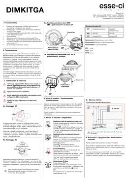
Wall Tamper Connector
A
Tx Rail
6
Dipswitches
B
Rx Rail
7
IR Lens
C
RC (Rx Master)
8
Battery Compartment
D
TC (Tx Master)
9
PCB Spring Locker
E
RX (Slave)
10 3 LED Bar
F
TX (Slave)
11 Alarm LED
1
Wall Tamper Cover
12 Flat Cable Connector
2
Swivel Cover
13 Tamper Switch
3
IR Filter Covering
14 Buzzer
2
Interruptores DIP
B
Rail Rx
6
Dipswitchs
7
Lente IR
C
RC (Rx Maître)
7
Lentilles IR
D
TC (Tx Maestro)
8
Compartimento Batería
D
TC (Tx Maître)
8
Compartiment Batterie
E
RX (Esclavo)
9
Resorte Sujeción PCB
E
RX (Esclave)
9
Ressort de fixation du PCB
10 Barra a 3 Led
F
TX (Esclavo)
10 Barra de 3 LEDs
F
TX (Esclave)
10 Barre 3 LED
Copertura Tamper
Antirimozione
11 Led Allarme
1
Cubierta Tamper
Pared
11 LED de Alarma
1
Couvercle d'AP à
l'arrachement
11 LED d'alarme
2
Copertura Snodo
13 Interruttore Tamper
2
Cubierta Rótula
2
Couvercle du pivot
3
Copertura IR
14 Buzzer
3
Cubierta Filtro IR
3
Couvercle Filtre IR
D
TC (Tx Master)
E
RX (Slave)
F
TX (Slave)
1
12 Connettore Piatto
0.5m - 2.5m
1.6ft - 8.2ft
FR Enlever les couvercles
Soulever et
enlever les
couvercles des
filtres IR.
B
C
D
RC
ON
1
2 3
4
9 10
7 8
5 6
SW4=OFF
TC
FR
1
2 3
4
SW1=OFF
EN
1234
ON
RC
I
+
RC
9 10
7 8
5 6
SW10=ON
(2 min.)
B
D
Rx
C
12 Câble de connexion plat
13 Contact d'AP
14 Sonnerie
Rx1
B
Rx2
Tx2
A
Ø
8mm
Tx
Rx
9.5°
d
en la pared. Si la distancia
entre las barreras Tx y Rx es de:
• Hasta 2 m: en el TC por el
interruptor DIP 4 en ON.
• 2 m a 5 m: en el TC por el
interruptor DIP 4 en OFF.
Connection
(optional):
A. On the RC (Rx
Master unit) set
Dipswitch 4 to OFF.
On the TC (Tx Master
unit) set Dipswitch 1 to
OFF.
B. Insert the 4 wall
tampers on the top and
bottom of each of the
Rx and Tx rails.
C. Press the PCB
Spring Lockers and
slide out the Master
and last Slave units of
both the Tx and Rx
rails.
D. Connect the wall
tamper cables to the
Wall Tamper
Connector.
EN Beam diameter = d
IT
IT Per la
connessione del
Tamper antirimozione
(opzionale):
A. Sull’RC (Rx Master)
impostare il
Microinterruttore 4 in
OFF. Sul TC (Tx
Master) impostare il
Microinterruttore 1 in
OFF.
B. Inserire i 4 Tamper
antirimozione negli
alloggiamenti di
entrambe le barriere.
C. Premere le Clip di
fissaggio
dell’elettronica e sfilare
il Master e l’ultimo
Slave di ogni barriera.
D. Innestare i cavi dei
Tamper antirimozione
ai loro connettori.
IT
FR Pour la
Tamper de Pared
(opcional):
A. En el RC (Unidad Rx
Maestro) colocar el DIP
4 en OFF. En el TC
(Unidad Tx Maestro)
colocar el DIP 1 en
OFF.
B. Colocar los 4
tampers de pared en la
parte superior e inferior
de las barreras Tx y Rx.
C. Presionar los
resortes de sujeción de
la PCB y deslizar hacia
afuera las unidades
Maestro y Esclavo de
las barreras Tx y Rx.
D. Conectar los cables
de los tamper al
Conector del Tamper de
Pared.
connexion de l'AP à
l'arrachement
(option) :
A. Sur le RC (Rx
Maître), placer le
Dipswitch 4 sur OFF.
Sur le TC (Tx Maître),
placer le Dipswitch 1
sur OFF.
B. Mettre les 4 AP à
l'arrachement en haut
et en bas des rails Rx
et Tx.
C. Appuyer sur les
ressorts de fixation du
PCB et retirer les
unités esclaves des
rails Tx et Rx.
D. Connecter les fils de
l'AP à l'arrachement
sur le connecteur de
l'AP à l'arrachement.
Canale B
Canal A
Canal B
FR
Canal A
Canal B
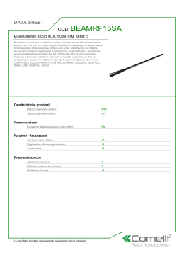
Installazione multipla. Nota: per associare il canale B porre in ON il Microinterruttore 3
dell’RC e del TC (Rx/Tx Master).
de las unidades maestro RC y TC en la posición ON.
d
17cm (0.6ft)
33cm (1.1ft)
50cm (1.6ft)
67cm (2.2ft)
84cm (2.8ft)
ES Conexión del
Canale A
ES Instalación de haces múltiple. Nota: Para configurar el Canal B, poner el interruptor DIP 3
d=0.17X
X
1m (3.2ft)
2m (6.5ft)
3m (9.8ft)
4m (13.1ft)
5m (16.4ft)
IT
ES
TC master units to the ON position.
FR Diamètre du faisceau = d
sur le mur. Si la distance
séparant les rails Tx et Rx est :
• Jusqu’à 2m : sur le TC,
mettre le Dipswitch 4 sur ON.
• De 2m à 5m : sur le TC,
mettre le Dipswitch 4 sur OFF.
Channel B
EN Multiple beam installation. Note: To configure Channel B set Dipswitch 3 on the RC and
Diametro barriera = d
ES d = diámetro del haz
FR Placer les rails Tx et Rx
B
EN Channel A
FR Installation multiple. Note : Pour configurer le canal B, placer le Dipswitch 3 des unités RC
et TC Maîtres en position ON.
6
Tx + Rx
= 1x
= 2x
+
A
+
C
= 3x
= 4x
B
EN
B
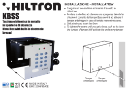
Perform system PCB identification:
A. Firstly insert a battery to the TC (Tx Master unit) and then insert a battery to the RC (Rx Master
unit). Pay attention to polarity.
B. The number of Alarm LED flashes indicates the number of PCB units connected in each of the
Rx and Tx rails. Make sure that the number of flashes are identical for the RC and TC units.
C. Insert remaining batteries.
Notes: In the case of low battery, the red Alarm LED will flash 4 consecutive times.
All batteries should be replaced at the same time.
A
4
A
Tx1
7
2 3
14 Zumbador
X
EN For Wall Tamper
ON
des pivots du haut des
rails Tx et Rx.
1
13 Interruptor Tamper
RC
ES Retirar las cubiertas de
ON
12 Conector Cable Plano
TC
A
Levantar y retirar
la cubierta del
filtro IR.
ES
Connecteur de l'AP à
l'arrachement
6
I
4
Alzare e
rimuovere la
copertura IR.
IT
5
Tx + Rx
Lift and remove
the IR filter
covering.
EN
Antenne du Récepteur
5
I
Tx + Rx
la rótula de la parte
superior e inferior de las
barreras Tx y Rx.
Clip di fissaggio
dell’elettronica
Rail Tx
4
RC (Rx Maestro)
+
FR Choisir le lieu de montage. S'assurer que l'étiquette TX / RX est en haut de chaque rail.
Rimuovere le coperture
degli snodi superiori ed
inferiori di entrambe le
barriere.
IT
9
A
+
ES Seleccionar una ubicación de montaje. Asegurarse que la pegatina TX / RX está en la parte superior de ambas barreras.
covers on the top and
bottom of both the Tx
and Rx rails.
Alloggiamento Batteria
FR
12 34
IT Scegliere un luogo per l’installazione. Assicurarsi che l’adesivo TX / RX sia posto nella parte superiore di ogni barriera.
EN Remove the swivel
8
Conector Tamper
Pared
Barrera Rx (Receptor)
RC (Rx Master)
ES Montar las barreras Tx y Rx
EN Select a mounting location. Make sure the TX / RX sticker is on the top of each rail.
3
Tx + Rx
Lenti IR
Barrera Tx (Emisor)
Antena Receptor
5
B
Barriera Rx
Rx a muro. Se la distanza
tra Tx e Rx è compresa tra:
• Fino a 2 m, sul TC posizionare
il microinterruttore 4 in ON.
• Da 2 a 5 m, sul TC posizionare
il microinterruttore 4 in OFF.
ES Aflojar los tornillos y extraer las
d’AP situés en haut et en bas
des rails Tx et Rx.
Microinterruttori
7
A
4
IT Installare le barriere Tx e
tamper superiore e inferiore di
entrambe le barriere Tx ed Rx.
FR Ouvrir et retirer les couvercles
6
ES
C
B
C
rails to the wall. If the
distance between the Tx
and Rx rails is:
• Up to 2m: on the TC set
Dipswitch 4 to ON.
• 2m to 5m: on the TC set
Dipswitch 4 to OFF.
IT Aprire ed estrarre i coperchi dei
cubiertas del tamper situadas
en la parte superior e inferior
de las barreras Tx y Rx.
Connettore per il Tamper
Antirimozione
ON
TX
EN Open and pull out the tamper
covers on the top and bottom
of both the Tx and Rx rails.
Barriera Tx
Antenna della Barriera Rx
5
EN Mount the Tx and Rx
5m/16.4ft max. (outdoor)
8m/26.2ft max. (indoor)
TO
P
A
4
TC
12
13
RC
1
I
9
9
2
I
IT
Antenna in Receiver Beam
12 34
Tx + Rx
TAMPER
RX
3
TAMPER
TX
+
1
4
ON
Model: RWT74
Installation Instructions
EN
F
E
5
1
TAMPER
Wireless IR Beam
D
TAMPER
A
Tx
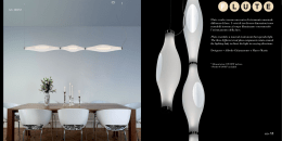
Perform Rx-Tx beam
alignment:
A. Set to Installation mode:
On the RC (Rx Master
unit) set Dipswitch 10 to
ON. Note that the
installation mode is active
for 2 minutes at a time.
B. Check the 3 LED bar for
the maximum signal
strength.
To improve signal strength:
C. Release the swivel
locking screw on the top
and bottom of both the Tx
and Rx rails.
D. Swivel the Tx and Rx rails
until maximum strength is
received.
IT
Effettuare
l’allineamento dell’Rx e
del Tx:
A. Porsi in modalità
Installazione: sull’RC (Rx
Master) impostare il
Microinterruttore 10 in
ON. Ricordarsi che la
barriera esce
automaticamente dopo 2
minuti dalla modalità
Installazione.
B. Guardare la Barra a 3 Led
per ottenere il massimo
allineamento.
Per aumentare la potenza
del segnale:
C. Allentare le viti di blocco
degli snodi superiori ed
inferiori delle barriere.
D. Ruotare il Tx e l’Rx sino a
che non si riceve il
segnale migliore.
-1-
ES
Alinear los haces
Rx-Tx:
A. Entrar en modo
Instalación: en el RC
(unidad Rx Maestro)
poner el DIP 10 en ON.
Tenga en cuenta que el
modo de instalación
estará activo durante 2
minutos.
B. Compruebe la barra de 3
LEDs para obtener la
máxima intensidad de
señal.
Para mejorar la intensidad
de la señal:
C. Soltar el tornillo de
fijación de la rótula de la
parte superior e inferior
de las barreras Tx y Rx.
D. Girar las barreras Tx y Rx
hasta recibir la máxima
señal.
FR Aligner les
faisceaux Rx-Tx :
A. Se mettre en mode
installation : Sur le RC
(Rx Maître), placer le
Dipswitch 10 sur ON.
Le mode d'installation
s'active alors pour 2
minutes.
B. Contrôler la barre 3
LED pour obtenir une
force de signal
maximale.
IT
Note: in caso di batteria scarica il LED rosso di allarme lampeggerà per 4 volte consecutive.
Tutte le batterie devono essere sostituite contemporaneamente.
ES
Pour améliorer la force du
signal :
C. Enlever la vis de
verrouillage de position
en haut et en bas des
rails Tx et Rx.
D. Faire pivoter les rails Tx
et Rx jusqu'à obtenir un
force de signal
maximale.
Riconoscimento del numero di moduli Slave collegati:
A. Inizialmente inserire una batteria nel TC (unità master Tx) e poi inserirla nell’RC (unità master
Rx). Prestare attenzione alla polarità.
B. Il numero di lampeggi del Led Allarme indica quanti moduli Slave sono collegati in ogni barriera.
Assicurarsi che il numero di lampeggi corrisponda sia nell’RC che nel TC.
C. Inserire le batterie rimanenti.
Identificar las PCB del sistema:
A. Poner primero una pila en el TC (unidad Tx Maestro) y después poner una pila en el RC
(unidad Rx Maestro). Prestar atención a la polaridad.
B. El número de parpadeos del LED de alarma indica el número de unidades PCB conectadas en
cada barrera Rx y Tx. Asegurarse de que el número de parpadeos es idéntico para las
unidades RC y TC.
C. Insertar las pilas restantes.
Notas: En caso de batería baja, el LED rojo de Alarma parpadeará 4 veces consecutivas.
Deben cambiarse todas las pilas a la vez.
FR
Faire une identification des PCB du système :
A. Insérer une batterie dans le TC (Tx Maître) et le RC (Rx Maître). Attention à la polarité.
B. Le nombre de clignotements de la LED d'alarme indique le nombre de PCB connecté dans
chaque rail Rx et Tx. S'assurer que le nombre de clignotements est identique pour le RC et le
TC.
C. Insérer les batteries restantes.
Notes : En cas de batterie basse, la LED rouge d’alarme clignotera 4 fois de suite.
Toutes les batteries devront être remplacées en meme temps.
EN Return to Normal mode: On the RC set Dipswitch 10 to OFF.
IT
12
11
8
Rx
RC
Per tornare in modalità Normale: Sull’RC riportare il Microinterruttore
10 in OFF.
ES Volver al modo Normal: en el RC poner el DIP 10 en OFF.
A
ON
1
FR Se mettre en mode normal : Sur le RC, placer le Dipswitch 10 sur OFF.
Set the Dipswitches on both the RC and
TC units as required.
EN
B
2 3
4
9 10
7 8
5 6
ON
IT
SW10=OFF
PANEL (Learn Mode)
EN
Centrale (modalità “Learn”)
RC
9 10
7 8
5 6
3 4
1 2
2
1
3
4
6
5
9
8
7
10
FR Centrale (Mode Adressage)
SW
9
10
Tx + Rx
Tx + Rx
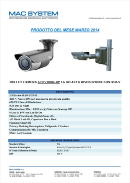
Function
1
i
2
Rx
RF Transmission
High*
Low
High
IR Beam Sensitivity
Low*
3
Channel
A*
B
Wall Tamper
Enable
Disable*
Alarm LED
Enable*
Disable
C
6&7
Interruption Time
See Table 1
See Table 1
Supervision Time
Every 65min* Every 15min
9
Hold Status
2.5 min*
10
Installation Mode
Off*
Immediate
On
* = Default
EN
EN Lock the swivel screws on
both the Tx and Rx rails.
Make sure that the alignment
remains fixed.
Tirare le viti degli snodi su
entrambe le barriere.
Assicurarsi che durante
l’operazione non si
disallineino.
+
I
RC
ES Fijar los tornillos de la rótula
en las dos barreras Tx y Rx.
Asegurarse de que se
mantiene la alineación.
EN
FR Revisser les vis de
verrouillage de position des
rails Tx et Rx. S'assurer que
l'alignement reste fixe.
13
IT
Test di rilevazione degli IR. Il Led Allarme deve
accendersi ad ogni rilevazione.
ES
Realizar una prueba de detección del IR. El
LED de Alarma deberá encenderse durante la
detección.
FR
Faire un test de détection IR. La LED d'alarme
devrait s'allumer lors d'une détection.
Tx + Rx
C
Perform IR detection test. Alarm LED should
light up during detection.
EN
IT
Technical Specifications
Receiver
B
D
C
Batteries
Battery Life
Current
Consumption
(normal mode)
0.5m unit:
1m unit:
100μA[AVR]@3V
70μA[AVR]@3V
RADIO FREQUENCY
RF Frequency
EN
IT
ES
FR
Close the Tx and Rx rails
according to the A, B, C, D
order in the diagram
above.
Modulation Type
Address Codes
Chiudere il Tx e l’Rx
seguendo i passi A, B, C,
e D del diagramma.
Size (L x W x D)
Cerrar las barreras Tx y
Rx según el orden
indicado en el diagrama
superior: A, B, C, D.
Fermer les rails Tx et Rx
en suivant l'ordre A, B, C,
D du diagramme cidessus.
Wall Tamper
v
4
Mode
Enable
IR Beam Sensitivity
Low*
Channel
A*
IR Signal Strength
High*
433.92/868.65MHz
ASK
16 million
-
Frequenza RF
-
Tipo di modulazione
Combinazioni per l’indirizzo
Weight
OPTICAL
Infrared Wave Length
-
940nm
ENVIRONMENTAL
Operation Temperature
Storage Temperature
RF Immunity
OFF
OFF
225ms*
OFF
ON
450ms
ON
OFF
675ms
ON
ON
900ms
IP65
4
Led Allarme
Abilitato*
Disabilitato
6&7
8
Supervisione
iv
iii
8
Ogni 65 minuti* Ogni 15 minuti
9
Blocco trasmissioni
2,5 minuti*
10
Modalità Installazione
Off*
Baja
Sensibilidad Haz IR
Baja*
Alta
2
A*
B
3
1
Tamper Antirimozione
Sensibilità IR
v
Canale
Potenza segnale IR
100μA[AVR]@3V
70μA[AVR]@3V
ASK
16 milioni
LED Alarma
Activado*
Desactivado
5
Ver Tabla 1
Ver Tabla 1
6&7
-
RTTE Compliance Statement:
RISCO Group and its subsidiaries and affiliates ("Seller") warrants its products to be free from defects in materials and workmanship under normal use for 24 months from the date of production. Because Seller does
not install or connect the product and because the product may be used in conjunction with products not manufactured by the Seller, Seller cannot guarantee the performance of the security system which uses this
product. Seller's obligation and liability under this warranty is expressly limited to repairing and replacing, at Seller's option, within a reasonable time after the date of delivery, any product not meeting the
specifications. Seller makes no other warranty, expressed or implied, and makes no warranty of merchantability or of fitness for any particular purpose. In no case shall seller be liable for any consequential or
incidental damages for breach of this or any other warranty, expressed or implied, or upon any other basis of liability whatsoever. Seller's obligation under this warranty shall not include any transportation charges or
costs of installation or any liability for direct, indirect, or consequential damages or delay. Seller does not represent that its product may not be compromised or circumvented; that the product will prevent any
personal injury or property loss by burglary, robbery, fire or otherwise; or that the product will in all cases provide adequate warning or protection. Buyer understands that a properly installed and maintained alarm
may only reduce the risk of burglary, robbery or fire without warning, but is not insurance or a guaranty that such event will not occur or that there will be no personal injury or property loss as a result thereof.
Consequently seller shall have no liability for any personal injury, property damage or loss based on a claim that the product fails to give warning. However, if seller is held liable, whether directly or indirectly, for any
loss or damage arising under this limited warranty or otherwise, regardless of cause or origin, seller's maximum liability shall not exceed the purchase price of the product, which shall be complete and exclusive
remedy against seller. No employee or representative of Seller is authorized to change this warranty in any way or grant any other warranty. WARNING: This product should be tested at least once a week.
Hereby, RISCO Group declares that this
equipment is in compliance with the
essential requirements and other relevant
provisions of Directive 1999/5/EC.
For the CE Declaration of Conformity
please refer to our website:
www.riscogroup.com.
-2-
Toutes les
65 min*
Toutes les
15 min
Immédiat
Off*
On
* = Por defecto
Función
1
i
2
Alta
* = Par défaut
TC
DIP
B
3
Alta*
Bassa
4
v
Modo
OFF
ON
Tamper Pared
Activado
Desactivado*
Sensibilidad Haz IR
Baja*
ii
A*
Alta
SW
Fonction
1
3
Potencia Señal IR
Alta*
Baja
4
Low
iii. Usati per regolare il tempo di risposta
d’attivazione dei fasci per prevenire falsi allarmi.
La minor velocità riduce la sensibilità.
iii. Se utiliza para ajustar la sensibilidad al entorno
para evitar falsas alarmas. Las configuraciones
más lentas reducen la sensibilidad.
Tabella 1
Tabla 1
Activé
Désactivé*
Sensibilité des
faisceaux IR
Faible*
Elevé
i
B
* = Por defecto
ON
AP à l'arrachement
ii
A*
Mode
OFF
2
Canal
ii. RC y TC deben usar el mismo canal.
Canal
v
Force du signal IR
A*
B
Elevé*
Faible
* = Par défaut
A noter :
i. Les paramètres du RC et TC doivent être
identiques.
ii. Les canaux du RC et TC doivent être
identiques.
iii. Utilisé pour ajuster la sensibilité à
l'environnement pour éviter les fausses
alarmes. Un paramètre plus lent réduit la
sensibilité.
Tableau 1
SW 6 SW 7 Tempo di Risposta
DIP 6 DIP 7 Tiempo Interrupción
OFF
OFF
225ms*
OFF
OFF
225ms*
SW 6 SW 7 Temps d'interruption
OFF
ON
450ms
OFF
ON
450ms
OFF
OFF
225ms*
ON
OFF
675ms
ON
OFF
675ms
OFF
ON
450ms
ON
ON
900ms
ON
ON
900ms
ON
OFF
675ms
ON
ON
900ms
iv. Para facilitar la prueba de paseo, durante los
primeros 10 minutos tras la instalación el
tiempo de reposo será inmediato y el LED de
alarma se encenderá con cada detección.
iv. Al fine di facilitare la prova di movimento durante
i primi 10 minuti dopo l’installazione sia il led di
allarme che la parte trasmittente saranno attivi.
v. Impostare questo Microinterruttore basandosi
sulla distanza che intercorre tra l’RC e il TC.
Segnale basso: 0.5m – 2m
Segnale alto: 2m – 5m
Se in modo normale di funzionamento vengono
riprodotti 2 toni acustici consecutivi, impostare
sull’unità TC il microinterruttore 4 su ON.
v. Configurar la potencia de transmisión en
función de la distancia entre las unidades RC y
TC.
Señal Baja: 0.5 m – 2 m
Señal Alta: 2 m – 5 m
Si en el modo Normal escucha 2 pitidos
consecutivos, ponga el DIP 4 de la unidad TC
en ON.
FR
Especificaciones Técnicas
Receptor
iv. Pour les besoins de la réalisation du test de
marche, le temps d’attente sera considéré
comme immédiat et la LED Alarme sera
allumée pendant les 10 premières minutes
après l’installation.
v. Paramétrer la puissance de transmission selon
la distance entre le RC et le TC.
Signal faible : 0.5m-2m
Signal élevé : 2m-5m
Si 2 bips consécutifs sont émis en mode
normal, mettre SW 4 sur ON sur le TC.
Spécifications Techniques
Transmisor
Récepteur
Transmetteur
ELECTRIQUE
Baterías
Duración Batería
Consumo
Unidad 0,5 m:
Corriente
Unidad 1 m:
(modo normal)
CR123A, Pila Litio 3 V
3 años, dependiendo del uso
60 μA [media] @ 3 V 50 μA [media] @ 3 V
100 μA [media] @ 3 V
70 μA [media] @ 3 V
Batteries
Durée de vie de la batterie
Consommation Unité de 0,5m :
de courant
Unité de 1m :
(mode normal)
Batterie Lithium CR123A, 3.0V
3 ans en utilisation normale
50μA[AVR]@3V
60μA[AVR]@3V
100μA[AVR]@3V
70μA[AVR]@3V
RADIO FREQUENCE
433,92/868,65 MHz
ASK
16 millones
-
Fréquence RF
-
Type de modulation
Codes d'adresse
433.92/868.65MHz
-
ASK
16 million
-
PHYSIQUE
Unidad 0,5 m: 500 x 40 x 42 mm
(unidad 19,6’’: 19.6 x 1.5 x 1,6’’)
Unidad 1 m: 1000 x 40 x 42 mm
(unidad 39,3’’: 39.3 x 1.5 x 1.6’’)
Unidad 0,5 m: 0,6 kg (1.3 lb)
Unidad 1 m: 1 kg (2.2 lb)
sin baterías
ÓPTICAS
Taille (L x l x P)
Unité de 0,5m : 500 x 40 x 42 mm
Unité de 1m : 1000 x 40 x 42 mm
Unité de 0,5m : 0,6kg
Unité de 1m : 1kg
Sans batterie
Poids
OPTIQUE
Longitud Onda Infrarrojo
-
940nm
Longueur d'onde IR
-
940nm
ENVIRONNEMENTAL
Temperatura Funcionamiento
Temperatura Almacenamiento
Inmunidad RF
-20°C a +60°C (4°F a 140°F)
-25°C a +60°C (13°F a 140°F)
Según EN 50130-4
Índice de Protección
RISCO Group Limited Warranty
Temps de supervision
iv
2.5 min*
MEDIOAMBIENTALES
IP65
Désactivé
Temps mort
ii. Il canale dell’RC e del TC deve essere identico.
Peso
Da -20°C a +60°C
Da -20°C a +60°C
Conforme alla norma EN 50130-4
Activé*
Mode d'installation
B
Tamaño (L x A x P)
940nm
LED d'alarme
Temps d'interruption Voir tableau 1 Voir tableau 1
9
FÍSICAS
0,5m: 500 x 40 x 42 mm
1m: 1000 x 40 x 42 mm
0,5m: 0.6kg
1m: 1kg
Senza batterie
Désactivé*
10
i. La configuración del RC y TC debe ser
idéntica.
Tipo de Modulación
Códigos de Dirección
8
Activé
On
i. La sensibilità dell’IR sull’RC e sul TC deve
essere identica.
Frecuencia RF
iii
B
AP à l'arrachement
Inmediato
High
-
4
Tiempo Interrupción
* = Default
-
Elevé
A*
Off*
RADIOFRECUENCIA
433,92/868,65MHz
Faible*
2,5 min*
ELÉCTRICAS
Batterie al Litio CR123A, 3.0V
3 anni, in base all’uso
50μA[AVR]@3V
60μA[AVR]@3V
Sensibilité des
faisceaux IR
Tiempo Reposo
Disabilitato*
Bassa*
Faible
Modo Instalación
ON
Abilitato
Elevé*
Canal
Desactivado*
TC
OFF
ON
Transmission RF
9
Modo
Funzione
Mode
OFF
10
nessun blocco
TC
SW
i
ii
Activado
Tiempo Supervisión Cada 65 min* Cada 15 min
iv
On
Alta*
Tamper Pared
5
1
Transmisión RF
Canal
6&7
Tempo di Risposta Vedi Tabella 1 Vedi Tabella 1
Trasmittente
OTTICA
Classe IP
Disabilitato*
Fonction
ON
Tenga en cuenta lo siguiente:
ES
Peso
Temperatura operativa
Temperatura di stoccaggio
Immunità RF
Abilitato
ii
SW
OFF
Notare quanto segue:
iv. For walk test purposes the hold-off time will be
immediate and the Alarm LED will be on during
the first 10 minutes after installation.
v. Set the transmission strength according to the
distance between the RC and TC units.
Low signal: 0.5m-2m
High signal: 2m-5m
If 2 consecutive beeps are heard in Normal
mode, on the TC unit set SW 4 to ON.
AMBIENTALI
-20°C to +60°C (4°F to 140°F)
-25°C to +60°C (13°F to 140°F)
According to EN 50130-4
Tamper Antirimozione
SW 6 SW 7 Interruption Time
Dimensioni (L x A x P)
Lunghezza d’onda dell’infrarosso
4
ON
Note the following:
i. The RC and TC setting must be identical.
ii. The RC and TC channels must be identical.
iii. Used to adjust the sensitivity to the surroundings
to avoid false alarms. Slower settings reduce
sensitivity.
Table 1
FISICHE
0.5m unit: 500 x 40 x 42 mm
(19.6 in. unit: 19.6 x 1.5 x 1.6 in.)
1m unit: 1000 x 40 x 42 mm
(39.3 in. unit: 39.3 x 1.5 x 1.6 in.)
0.5m unit: 0.6kg (1.3lb)
1m unit: 1kg (2.2lb)
without batteries
3
Modo
Disable*
* = Default
FREQUENZA RADIO
PHYSICAL
IP Rating
1
Ricevente
Batterie
Autonomia batterie
Assorbimento modello da 0,5m:
(modalità
modello da 1m:
Normale)
i
2
B
4
OFF
ELETTRICHE
CR123A, 3.0V Lithium Battery
3 years typical, depends on usage
50μA[AVR]@3V
60μA[AVR]@3V
1
Alta
3
Specifiche Tecniche
Transmitter
ELECTRICAL
3
Function
3
B
Bassa
A*
ii
4
SW
i
D
A
2
ii
Paramétrer la communication entre le RC (Rx Maître)
et la centrale de sécurité :
A. Mettre la centrale en mode Adressage
B. Placer le Dipswitch 4 (AP à l'arrachement) du RC sur ON.
C. Appuyer sur le ressort d'AP pendant 5 secondes.
D. Si l'AP à l'arrachement a été connectée (voir étape 5),
remettre le Dipswitch 4 en position OFF.
FR
Alta*
Bassa*
i
2
Configurar la comunicación entre el RC (unidad Rx
Maestro) y la central de seguridad:
A. Poner la central en modo Aprendizaje.
B. Poner el DIP 4 (Tamper Pared) del RC en ON.
C. Presionar el muelle del tamper durante 5 segundos.
D. Si se han conectado previamente los tampers (ver paso
5), volver a colocar el DIP 4 en la posición OFF.
ES
Potenza segnale
Canale
2
ON
Impostare la comunicazione tra l’RC (Rx Master) e la
centrale:
A. Porre la centrale in modalità “Learn” (Ascolto).
B. Spostare il Microinterruttore 4 dell’RC in ON.
C. Premere l’interruttore del Tamper per 5 secondi.
D. Se sono stati abilitati i Tamper antirimozione (vedere
punto 5) riportare il Microinterruttore 4 in OFF.
IT
O
N
1234
IT
TC
1
ON
Función
* = Default
iv
Set communication between the RC (Rx Master unit)
and the security panel:
A. Set the panel to Learn mode.
B. Set Dipswitch 4 (Wall Tamper) on the RC to ON.
C. Press the tamper spring for 5 seconds.
D. If wall tampers have been previously connected (see
step 5) set Dipswitch 4 back to the OFF position.
OFF
Placer les Dipswitchs sur les RC et TC
comme souhaité.
FR
RC
DIP
Sensibilità IR
iii
5
Modo
3
5
4
8
1
ii
5 sec.
iii
Funzione
i
ON
ii
Tx
RC
SW
2
Mode
OFF
Configurar los interruptores DIP de las
unidades RC y TC según sea necesario.
ES
RC
ON
SW4=ON
ES Central (Modo Aprendizaje)
Impostare i Microinterruttori delle barriere
come da necessità installative.
IT
IP65
Température de fonctionnement
Température de stockage
Immunité RF
Indice de protection IP
Contacting RISCO Group
RISCO Group is committed to customer service and product support. You can contact us through our website www.riscogroup.com or as follows:
United Kingdom
Tel: +44-161-655-5500
[email protected]
USA
Spain
Tel: +1-631-719-4400
Tel: +34-91-490-2133
[email protected] [email protected]
Italy
Tel: +39-02-66590054
[email protected]
France
Tel: +33-164-73-28-50
[email protected]
Belgium
Tel: +32-2522 7622
[email protected]
-20°C à +60°C
-25°C à +60°C
Selon la norme EN 50130-4
Brazil
Tel: +55-11-3661-8767
[email protected]
Poland
Tel: +48-22-500-28-40
[email protected]
China
Tel: +86-21-52-39-0066
[email protected]
Israel
Tel: +972-3963-7777
[email protected]
IP65
FCC Note:
Only the 433,92 Mhz version is FCC
approved and to be sold in US.
The manufacturer is not responsible for any
radio or TV interference caused by
unauthorized modifications to this
equipment. Such modifications could void
the user’s authority to operate the
equipment
All rights reserved. No part of this
document may be reproduced in any form
without prior written permission from the
publisher.
© RISCO Group 05/10
5IN1326 D
Scaricare