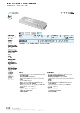
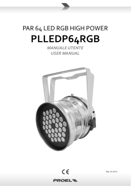
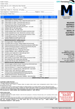
Overled is a brand of DDS Elettronica S.r.l. - Via Nicolò Biondo 171 - 41100 Modena Italy - www.overled.com
C.F. partita Iva It02275360366 - capitale i. V. 50.000,00euro - telefono +39.059.822993 fax +39.059.823573
D
D
S
OverledBUSpilot è un sistema di trasmissione DMX over power, si tratta di trasmissione
del DMX/RDM sulla alimentazione da 12Vdc fino al max 50vdc, senza che sia
necessario polarizzare i conduttori. Questo permette di semplificare il cablaggio e di
rendere possibile la installazione in piscine o fontane dato che si alimenta in bassa
tensione. Il numero massimo di dispositivi slave collegabili sul BUS in parallelo è 32 per
Pilot,con massimo 8 byte di dati (DMX 8 canali/slot per modulo driver collegato alla
lampada),mentre il carico totale massimo ammesso è di 500Watt @24vdc.Il Pilot è
compatibile con sistemi ART NET dove può anche essere utilizzato come nodo ad un
universe DMX, oppure puo essere controllato tramite DMX input rimanendo
compatibile con RDM,permettendo tutte le azioni possibili di settaggio canali DMX e
personalità, e viene visto dal DMX come oggetto trasparente, cioè si comunica
direttamente con i moduli ad esso collegati. Il Pilot è anche utilizzabile come DMX
recorder dotato di SD per memorizzare degli Show,e di ingressi digitali per attivare
appunto la funzione di memorizzazione e di play degli show.La comunicazione sul bus
è di tipo time slot dove OverledBUSpilot II è il master che fornisce ai moduli driver
alimentazione e DMX negli stessi conduttori elettrici, i conduttori che collegano i moduli
driver al Pilot dovranno opportunamente essere dimensionati per il carico e per la
lunghezza.
OverledBUSpilot:
- RDM/DMX/ArtNet to OverLed Bus
Network
- ArtNet to DMX
- ArtNet Recorder
- DMX Recorder
- ArtNet + DMX Player
verled
OverledBUSpilot it’s a data over power,the DMX signal or ART NET is coupled and
transmitted over power. The power supply for OverledBusPilot can be from12VDC up to
50VDC, the DMX/RDM data trasmission over power is made by Pilot, with correct cable
gauge depending on the total power required from the fixture connected.The maximum
number of the fixture are 32, the maximum DMX channel (Slot) per fixture are 8, the
maximum power is 500W @24Vdc, and 100mt cable.OverledBUSpilot it is also a DMX
recorder and ART NET node for one Universe (512 DMX channel). OverledBUSpilot it is
the MASTER of the entire system, where the data are transimitted in time slot, error free,
if a data packet isn’t received correctelely from the slave module (driver or node), this will
be sent again in 20-35mSec. OverledBUSpilot, it is a poprietary Overled bus.
The OverledBUS system require Master (OverledBUSpilot) and Slave
OverledBUSdriver or node, those board can drive LED or STRIP led. The
OverledBUSdriver board can be integrated with the lamp (OEM module), the
OverledBUSnode it is native in a box, for wall applications, with screw driver connectors
for the Harness.
OverledBUSpilot II
Overled is a brand of DDS Elettronica S.r.l. - Via Nicolò Biondo 171 - 41100 Modena Italy - www.overled.com
C.F. partita Iva It02275360366 - capitale i. V. 50.000,00euro - telefono +39.059.822993 fax +39.059.823573
D
D
S
DDS629B puo' fungere da ricevitore DMX (DMX In mode) o generatore DMX (DMX Out Mode).La modalita' viene
selezionata mediante comando via ethernet utilizzando il software eSuite o JArtNet. L'IP di default e' 10.0.0.190.Lo stato e la
modalita' di funzionamento sono indicati dai 5 led, descritti piu' avanti.Quando si trova in DMX In Mode, il dispositivo risponde
a tutti i comandi RDM standard (impostazione personalita', indirizzo DMX di base, indirizzo DMX dei singoli point
OverledBus, etc etc).Se viene avviato il Play di uno show registrato su sd-card, il dispositivo diventa temporaneamente un
generatore DMX anche se la modalita' selezionata e' DMX In.Se il dispositivo viene lasciato in modalita' DMX Out e non si
dispone di connessione Ethernet per riportarlo in DMX In, applicare segnale DMX in ingresso ed accendere il dispositivo: il
segnale viene rilevato e provoca la commutazione in modalita' Dmx In.
Device Led Status
Show selector INPUT
Funzioni degli Ingressi:
Il dispositivo dispone di 4 ingressi digitali (IN1 – IN4) la cui funzionalita' e' di seguito descritta.
Ingressi IN1-IN2: lancio in PLAY di uno di tre show registrati su sd-card, secondo la seguente tabella. 0 = ingresso non
attivo; 1 = ingresso attivo (chiuso sul morsetto del comune):
IN2
0
0
1
1
IN1
0
1
0
1
Risultato
Stop
Play dello show n. 1
Play dello show n. 2
Play dello show n. 3
IN3:
Riservato per future espansioni
IN4:
Comando di Play Stop / Play Start / Record Stop / Record Start su singolo tasto:
L'ingresso IN4 e' utile in caso si desideri registrare uno show in una delle tre posizioni disponibili.Una pressione breve
produce lo stop di un eventuale Play / Record in corso. Se il dispositivo e' gia' in Stop, produce l'avvio dello show selezionato
sugli ingressi IN1-IN2. Se gli ingressi sono entrambi a riposo, verra' avviato lo show n. 1 oppure l'ultimo show attivato via
Ethernet (1-999).
Per lanciare un Play non e' necessario agire su IN4, perche' gli ingressi IN1-IN2 eseguono questa operazione
automaticamente nel momento in cui cambia il loro stato.
Volendo registrare uno show, agire come segue:
- Selezionare il n. dello show che si desidera registrare (1-3) agendo sugli ingressi IN1-IN2;
- Se uno show e' presente (e quindi e' partito in PLAY), fermarlo attivando brevemente IN4;
- Fornire il segnale da registrare (su DMX In oppure ArtNet);
- Avviare la registrazione attivando IN4 per > 2 secondi;
- Per terminare la registrazione, attivare brevemente In4.
Le funzioni degli ingressi non impediscono il regolare funzionamento di comandi di PLAY /RECORD impartiti da eSuite o
JartNet. A tale scopo, agiscono solo su cambiamento dello stato.
E' possibile lasciare scollegati gli ingressi ed ottenere egualmente il funzionamento del PLAY / REC da remoto via ethernet,
nonostante IN1-IN2 siano a 0 (condizione che normalmente corrisponde a STOP).Il numero di show selezionato da remoto
via ART NET (ethernet) (1 – 999) rimane operativo ed e' possibile lanciarlo successivamente in PLAY anche mediante
attivazione breve di IN4. Viene revocato soltanto agendo sugli ingressi IN1-IN2, perche' essi selezionano lo show 1-3 in base
al proprio stato.
Lo stato degli ingressi IN1-IN2 puo' essere alterato in tutte le combinazioni; non c'e' bisogno di passare per lo STOP per
attivare il play di uno show diverso. Il dispositivo provvede a chiudere preventivamente il file di un eventuale show in corso,
prima di lanciare quello nuovo.
In caso di avvio del PLAY mediante comando ethernet, il dispositivo ricorda il proprio stato anche in caso di spegnimento
dell'alimentazione ed esegue il play dello show eventualmente attivato precedentemente.Se pero' gli ingressi IN1-IN2 sono
diversi da zero, verra' attivato lo show da essi selezionato.
verled
Power supply 12-50Vdc
Overled BUS
DMX/RDM
ART NET (Ethernet)Port
SD memory card FAT 32
ART NET (ethernet) Led status
Overled is a brand of DDS Elettronica S.r.l. - Via Nicolò Biondo 171 - 41100 Modena Italy - www.overled.com
C.F. partita Iva It02275360366 - capitale i. V. 50.000,00euro - telefono +39.059.822993 fax +39.059.823573
D
D
S
DDS629B This board can be used as ART Net to DMX interface, or DMX recorder. The operation mode can be selected by
ethernet command or using software Esuite, Default factory IP address ia 10.0.0.190. The operation mode status is indicated
DDS629B
board canin
bethe
used
ART Net to DMX interface, or DMX recorder. The operation mode can be selected by
by 5 led,This
as mentioned
nextaspage.
ethernet
command
or using
software
Esuite,
Default
factoryRDM
IP address
ia 10.0.0.190. The(personality
operation mode
status is address,Dmx
indicated
During
DMX
mode
operation,
the
device
can
setting,DMX
DDS629B
This
board
can
be
used
as
ART
to
DMreceive
interface,
or2.0
DMstandard
recorder.command
The operation mode can
be selected
by
by 5address
led, as mentioned
in the next
page. Net
of each
connected
overledbus
nodefactory
node, ecc.ecc.)
ethernet
command
or
using
software
Esuite,
Default
IP
address
is
10.0.0.190.
The
operation
mode
status
is
indicated
During
DMX
mode
operation,
the
device
can
receive
RDM
2.0
standard
command
(personality
setting,DMX
address,Dmx
playng a show
on the SD CARD the device is a DMX generator also if the operation mode is DMX IN. If the
by 5address
led,Ifasismentioned
in therecorded
next
page.
of each
connected
overledbus
nodeconnection
node, ecc.ecc.)
device
is inoperation,
DMX
operation
no Ethernet
available
, tocommand
bring back to DMX Input,
applyDMX
external DMXDmx
generator to
During
DMX
mode
the
device
canCARD
receive
RDM
2.0
standard
setting,
If is DMX
playng
a
show
recorded
on
the
SD
device
is
a DMX
generator (personality
also if the operation
modeaddress,
is DMX IN. If the
and
power on overledbus
DDS629B, the
unitecc.)
go to the
DMX
IN Operation
automatically.
address
of
each
connected
node,
device is in DMX operation no Ethernet connection available , to bring back to DMX Input, apply external DMX generator to
If is DMX
playing
a power
show recorded
on the
CARD
the device
is a DMX
generator also if the operation mode is DMX IN. If the
and
ondescription:
DDS629B,
theSD
unit
go to DMX
IN Operation
automatically.
device isAvailble
in DMXinput
operation
no Ethernet connection available , to bring back to DMX Input, apply external DMX generator to
DMXAvailble
and power
ondescription:
DDS629B, the unit go to DMX IN Operation automatically.
The input
device
has 4 digital input (IN1 – IN4)
Available
input description:
The Input
device
has
4 digital
input (IN1 – IN4)
IN1-IN2:
Run prerecordered
Shows on sd-card, in accorrding to table below:
The Input
device
has
4
digital
input
(IN1
–
IN4)
Run prerecordered
on sd-card,
in accorrding
table below:
0IN1-IN2:
= input false
1 = input trueShows
(connecting
with common
on thetoconnector):
Input0IN1-IN2:
Run
prerecordered
Shows
on
sd-card,
in
according
to
table
below:
= IN2
input false
true (connecting with common on the connector):
IN11 = inputFunction
0 false 1 0= input true
Stop
0 = IN2
input
(connecting with common on the connector):
IN1 1
Function
0
Play show n. 1
0 1
0 0
StopPlay show n. 2
IN2 0
IN1 1
Function
Play show
n. 1 n. 3
show
0 1 1 0 0 1 StopPlayPlay
show n. 2
0 1
1 1
PlayPlay
show
n. 1 n. 3
show
IN3:
Reserverd
for
future
1
0
Play show
n.
2 use
Comand
Play n.
Stop
/ Play Start / Record Stop / Record Start on toggle:
1 IN3:IN4:
1 Reserverd
Play for
show
3
future use
IN4:To record
Comand
Play
Stop
/
Play
/ Record
/ Record
Start with
on toggle:
a show
in theuse
SD card,Start
select
one of 3Stop
show
in according
the table above,connecting to input connectors the
IN3:
Reserved
for future
combination
for
the
number
of
the
show
you
want,then
connect
input4
shortelely to ensure there are no show in play, then
IN4:To record
Command
Play
Stop
/
Play
Start
/
Record
Stop
/
Record
Start
on
toggle:
showstep:
in the SD card, select one of 3 show in according with the table above,connecting to input connectors the
follow athose
combination
fornumber
the number
of the
you
want,then
connect
input4 shortelely to ensure there are no show in play, then
-Select
the
of show
youshow
wantof
record
byininput
1-3 with
To record
a
show
in
the
SD card,
select
one
3 show
according
the table above, connecting to IN1-2 connectors the
follow
those
step:
-Send
DMX
signal toof
DMX
input or
send
ART
NET
combination
for
the
number
the
show
you
want,
then
connect
input4
shortely to ensure there are no show in play, then
-Select
the
number
of
show
you
want
record
by
input
1-3
- connect
input 4 > 2 second
follow
those
step:
-Send
DMX
signal toconnect
DMX input
or 4send
ART NET
- stop
recording
input
shortelely
-Select
the
number
show
you want
record
by input 1-3
- connect
input of
4of>DDS629
2 second
Thesignal
status
can
be monitored
-Send
DMX
to
DMX
input
or
send
ART
NETby LED.
- stop
recording
connect
input
4
shortelely
Toinput
make
SHOW in play mode just switch IN1-IN2 they automatically play the show number as specified by IN 1 and 2.
- connect
4 >run
2 second
The In
status
of
DDS629
can
be
monitored
by
LED.
case connect
of ART NET
comnand
PLAY/ RECORD
will be accepted with priority respect digital input, ART NET can be found in
- stop
input
4mode
shortelely
Torecording
make
run
SHOW or
in
play
just switch IN1-IN2 they automatically play the show number as specified by IN 1 and 2.
Esuite
software
Jartnet.
The In
status
of
DDS629
can
be
monitored
by
LED.
case of ART NET comnand PLAY/ RECORD will be accepted with priority respect digital input, ART NET can be found in
To make
run
SHOW or
in play
mode just switch IN1-IN2 they automatically play the show number as specified by IN 1 and 2.
Esuite
software
Jartnet.
Switching
the
In1
and In2
will change
the will
show
Play immediately
asrespect
soon thedigital
first selceted
is finishied
In case of
ART NET
command
PLAY/
RECORD
beinaccepted
with priority
input, ART
NET can be found in
Lo statoordegli
ingressi IN1-IN2 puo' essere alterato in tutte le combinazioni; non c'e' bisogno di passare per lo STOP per
Esuite
software
Jartnet.
Switching
the
In1
and
In2
will
change
the
show
in
Play
immediately
as
soon
the
first
selceted
is
finishied
attivare
playIn2
di uno
show diverso.
Il dispositivo
provvede a chiudere
il file
di un eventuale show in corso,
Switching
the In1il and
will
change
the show
in Play
immediately
soon the preventivamente
firstnon
selected
show
isdi
finished.
Lo stato
ingressi
IN1-IN2
puo'
essere
alterato
in tutte le as
combinazioni;
c'e' bisogno
passare per lo STOP per
primadegli
di lanciare
quello
nuovo.
attivare il play di uno show diverso. Il dispositivo provvede a chiudere preventivamente il file di un eventuale show in corso,
prima
lanciare
quello
In di
caso
di avvio
delnuovo.
PLAY mediante comando ethernet, il dispositivo ricorda il proprio stato anche in caso di spegnimento
dell'alimentazione ed esegue il play dello show eventualmente attivato precedentemente.Se pero' gli ingressi IN1-IN2 sono
In caso
di avvio
delverra'
PLAYattivato
mediante
comando
ethernet,
il dispositivo ricorda il proprio stato anche in caso di spegnimento
diversi
da zero,
lo show
da essi
selezionato.
dell'alimentazione ed esegue il play dello show eventualmente attivato precedentemente.Se pero' gli ingressi IN1-IN2 sono
diversi da zero, verra' attivato lo show da essi selezionato.
verled
Device Led Status
Show selector INPUT
Power supply 12-50Vdc
Overled BUS
DMX/RDM
ART NET (Ethernet)Port
SD memory card FAT 32
ART NET (ethernet) Led status
Overled is a brand of DDS Elettronica S.r.l. - Via Nicolò Biondo 171 - 41100 Modena Italy - www.overled.com
C.F. partita Iva It02275360366 - capitale i. V. 50.000,00euro - telefono +39.059.822993 fax +39.059.823573
Show selector
Led Status
LED Status Dispositivo
LED 3 = verde
LED 6 = Rosso
LED 7 = Giallo
Alla accensione si ha led6 Rosso che lampeggia durante caricamento del bootloader, poi Giallo LD7 che
indica la fase di detect DMX In, che puo' revocare eventuale stato di DMX Out Mode. Infine, rimane acceso
led3 Verde o led6 Rosso a seconda della condizione di funzionamento, descritta di seguito:
Ld3 Verde ON = Dmx Input mode;
Ld3 Verde Flash = Dmx presente in ingresso
Ld6 Rosso ON = Dmx Output mode;
Ld6 Rosso Flash = ArtNet in ingresso
Se c'e' ArtNet ma dispositivo in DMX In mode, avremo combinazione di Verde ON e Rosso flashing (tx
solo verso Overled Bus)
Durante il funzionamento, il led Giallo si accende se il primo canale DMX / ArtNet e' >= 128 (monitor di
ricezione).
Logica di segnalazione Led per il player:
Led3 Verde slow flash = PLAY (sd-card)
Led3 Verde very slow flash = Show automatico
Led6 Rosso slow flash = RECORD; se ci sono frames in ingresso (come deve essere),
contemporaneamente Verde flash 25%.
Se play/rec in pausa, rispettivo led lampeggia con duty 20% (praticamente un blink lento).
Se errore sd-card, Rosso slow_flash con duty 90% per tre secondi.
Power supply 12-50Vdc
Overled BUS
DMX/RDM
ART NET Port
SD memory card FAT 32
ART NET Led status
D
D
S
Segnalazioni LED
I led giallo/rosso sul lato connettore Ethernet indicano lo stato del link ethernet (art net):
- Entrambi spenti = cavo scollegato
- Rosso acceso / lampeggiante = link a 10mbit LED 9
- Giallo acceso / lampeggiante = link a 100mbit LED 10
verled
Tabella esaustiva segnalazioni Led:
Condizione
LED6
LED 3
ROSSO VERDE
DMX IN Mode, nessun segnale in ingresso
off
on
DMX IN mode, DMX In presente, trasmissione ArtNet + OverledBus
off
flash
DMX IN mode, ArtNet In presente, trasmissione OverLedBus flash
on
DMX OUT, nessun segnale in ingresso
on
off
DMX OUT, ArtNet IN presente, generazione DMX OUT + OverledBus flash
off
Se filtro universi attivo, abbiamo 25% di duty sul verde:
flash
flash 25%
sd-card REC in corso; verde lampeggia se ci sono frames in entrata slow_flash flash)
sd-card PLAY in corso
off
slow_flash
show automatico in corso
off
very_slow_flash
Errore sd-card
slow,90% off
Sia Play che Rec: se in pausa, il rispettivo led lampeggia con duty 20%
Un Nodo sta registrandosi su piu' di uno slot (normale al power-on)
on
on
Un Nodo non ha completato registrazione (linea difficoltosa)
fast_flash
fast_flash
OverledBUSpilot
Overled is a brand of DDS Elettronica S.r.l. - Via Nicolò Biondo 171 - 41100 Modena Italy - www.overled.com
C.F. partita Iva It02275360366 - capitale i. V. 50.000,00euro - telefono +39.059.822993 fax +39.059.823573
Show selector
Led Status
LED status Art NET Ethernet
Yellow and RED LED (9-10) indicate Ethernet status:
-Both off = cavo scollegato
- Red on - blinking = link a 10mbit
- Yellow on - blinking = link a 100mbit
LED Status device
LED 3 = verde
LED 6 = Rosso
LED 7 = Giallo
At power on LED6 (red) blink during boot loader loading, yellow Ld7 on, DMX detection this can stop DMX
out operation (in case play of show DMX become output), LED 3 and LED 6 are indicating the following
status
Ld3 Green ON = Dmx Input mode
Ld3 Green Flash = Dmx engaged
Ld6 Red
Ld6 Red
If ART NET is receiving and device is in DMX mode, green LED is on and RED LED is flashing the data
are transmitted to OverledBUS
During OverledBUS data transmission yellow LED on means first DMX channel is sending data value >
128 bit (receiving monitor).
Player mode LED indicatio:
Led3 Green slow flash = PLAY (sd-card) the recorded show is in play
Led3 Green very slow flash = Automatic Show
LED 6 RED slow flash = RECORD if DMX input is receiving data frames, in mean time the green led
flash at 25%.
Play/rec in pause, RED led blink duty 20% , slow blink.If an error occur on SD-CARD Red led flash
with 90% of duty for 3 second.
Power supply 12-50Vdc
Overled BUS
DMX/RDM
ART NET Port
SD memory card FAT 32
Reference table for LED:
Condiction
LED6
RED
DMX IN Mode, no signal in
DMX IN mode, DMX Engaged, trasmission ArtNet + OverledBus
DMX IN mode, ArtNet In available, trasmission OverLedBus
DMX OUT, no signal in
DMX OUT, ArtNet IN ,
DMX OUT + OverledBus
Universe filter on , 25% duty on GREEN
sd-card REC in progress; GREEN blink if DMX frames input
sd-card PLAY
Auto Show n progress
sd-card Error
Play or REC pause led blink duty 20%
Node during connection to pilot
(normal at power-on)
Node not registered line problem
off
on
off
flash
flash
on
on
off
flash
off
flash
flash 25%
slow_flash flash)
off
slow_flash
off
very_slow_flash
slow,90% off
ART NET Led status
D
D
S
ON = Dmx Output mode to slave unit
Flash = ArtNet input
verled
OverledBUSpilot
on
fast_flash
LED 3
GREEN
on
fast_flash
S
Sub Net device
DMX address
Slave Discovery
Slave identification on bus
Overled is a brand of DDS Elettronica S.r.l. - Via Nicolò Biondo 171 - 41100 Modena Italy - www.overled.com
C.F. partita Iva It02275360366 - capitale i. V. 50.000,00euro - telefono +39.059.822993 fax +39.059.823573
OverledBUSpilot
verled
D
D
RDM Setting Screen shot
24VDC
12VDC
6VDC
DIGITAL IN
480W
.5W
WATT
58mm
90mm
87mm
DIN bar mounting
Overled is a brand of DDS Elettronica S.r.l. - Via Nicolò Biondo 171 - 41100 Modena Italy - www.overled.com
C.F. partita Iva It02275360366 - capitale i. V. 50.000,00euro - telefono +39.059.822993 fax +39.059.823573
S
0.1A
MAX
TYP
Min
10A
CURRENT
.15A
11,5
49,5
VOLTAGE
OverledBUSpilot
verled
D
D
Electrical
Overled is a brand of DDS Elettronica S.r.l. - Via Nicolò Biondo 171 - 41100 Modena Italy - www.overled.com
C.F. partita Iva It02275360366 - capitale i. V. 50.000,00euro - telefono +39.059.822993 fax +39.059.823573
D
D
S
Cablaggio
Wiring:
Alimentatore12-48Vdc
dimensionato
per il carico lampade
12/48vdc power supply
External switching power
supply 12-48VDC out with
correct power for the load.
110/220VAC
cavo 2 poli non polarizzato con sezione appropriata
MAX 300mt
Lampada led con OverledBUSdriver installato all’interno
Led fixture with embedded OvrledBUSdriver embedded
verled
modulo #1 .... #32
module #1 .... #32
OverledBUSpilot
Overled is a brand of DDS Elettronica S.r.l. - Via Nicolò Biondo 171 - 41100 Modena Italy - www.overled.com
C.F. partita Iva It02275360366 - capitale i. V. 50.000,00euro - telefono +39.059.822993 fax +39.059.823573
D
D
S
DMX cable specification
Cable shielding Ethernet:
Main article: Electromagnetic shielding
STP cable format
DESCRIPTION: Round Cable Sec. 2x0.25 mm² d.5.50 mm
DESCRIZIONE: Cavo tondo sez. 2x0.25 mm² d.5.50 mm
Twisted pair cables are often shielded in attempt to prevent
electromagnetic interference. Because the shielding is made of metal,
it may also serve as a ground. However, usually a shielded or a
screened twisted pair cable has a special grounding wire added called
a drain wire. This shielding can be applied to individual pairs, or to the
collection of pairs. When shielding is applied to the collection of pairs,
this is referred to as screening. The shielding must be grounded for the
shielding to work.Shielded twisted pair (STP or STP-A) STP cabling
includes metal shielding over each individual pair of copper wires. This
type of shielding protects cable from external EMI (electromagnetic
interferences). e.g. the 150 ohm shielded twisted pair cables defined
by the IBM Cabling System specifications and used with token ring
networks.Screened unshielded twisted pair (S/UTP) Also known as
Foiled Twisted Pair (FTP), is a screened UTP cable (ScTP).
Screened shielded twisted pair (S/STP or S/FTP) S/STP cabling, also
known as Screened Fully shielded Twisted Pair (S/FTP), is both
individually shielded (like STP cabling) and also has an outer metal
shielding covering the entire group of shielded copper pairs (like
S/UTP).This type of cabling offers the best protection from interference
from external sources, and also eliminates alien crosstalk.
Note that different vendors and authors use different terminology (i.e.
STP has been used to denote both STP-A, S/STP, and S/UTP) .
FLAMAR COD:
CUSTOMER CODE:
C
D
-
B
A
Filler
A
Conductor Conduttore
Material
Conductor nr.
Stranding
Section nom
Electric resistance
Materiale
N.dei conduttori
Trefolatura
Sezione nominale
Resistenza elettrica
Bare Copper
2
14x0.15
0.25
<77.5 (IEC 344)
Insulation material
Color ins.
Hardness ins.
Diameter
Materiale di isolam.
Colore isolamento
Durezza isolamento
Diametro
PE
Red-Blue
55
1.75+/-0.10
1th Shielding
1° Schermo
Material
2nd Shielding
2° Schermo
Material
Avg. coverage
Electric resistance
Material
Color
Hardness
Diameter
Temperature Rating:
Voltage Rating:
Dielectric Strength
Capacità nominale c/c
Impedenza nominale
C
Tin Copper
95
<35
%
Ω/km
PVC
Black
76
5.50+/-0.20
Shore A
mm
D
Materiale
Colore
Durezza
Diametro
da definire
-20°C to +70°C
30V (Only Electronic use, not for Power)
2000Vx1’
64 pF/m
120 Ohm
Cable conforming to:
Standard 2002/95/CE (RoHS)
Packaging Confezionamento
Bobina d.230
OverledBUSpilot
Shore D
Tape Al-Pet ( Al outside)
Materiale
Copertura media
Resistenza elettrica
Protectiv Cover Guaina
mm
mm²
Ω/km
B
Materiale
Marcatura a ink-jet
verled
OUTLINE - SCHEMA
Overled is a brand of DDS Elettronica S.r.l. - Via Nicolò Biondo 171 - 41100 Modena Italy - www.overled.com
C.F. partita Iva It02275360366 - capitale i. V. 50.000,00euro - telefono +39.059.822993 fax +39.059.823573
D
D
S
DMX connector
Ethernet connectors
TIA/EIA-568-B T568A Wiring Pin
Pair Wire Color
1
3
tip
Pair 3 Wire 1
white/green
2
3
ring Pair 3 Wire 2
green
Pin
Pair Wire
1
2
tip
1 white/orange
2
2
ring
2 orange
3
3
tip
verled
Color
Pair 2 Wire
Pair 2 Wire
Pair 3 Wire
OverledBUSpilot
Pin 1 = signal reference = cable shield
Pin 2 = signal inversion = ' - ' or B, blue
Pin 3 = signal = ' + ' or A, red
Pin 4 = not used
Pin 5 = not used
Overled is a brand of DDS Elettronica S.r.l. - Via Nicolò Biondo 171 - 41100 Modena Italy - www.overled.com
C.F. partita Iva It02275360366 - capitale i. V. 50.000,00euro - telefono +39.059.822993 fax +39.059.823573
D
D
S
DMX512
Developed by the Engineering Commission of United States Institute for Theatre Technology (USITT), the standard was created in 1986, with
subsequent revisions in 1990 leading to USITT DMX512/1990.DMX512-A In 1998 the Entertainment Services and Technology Association
(ESTA) began a revision process to develop the standard as an ANSI standard. The resulting revised standard, known officially as "Entertainment
Technology — USITT DMX512-A — Asynchronous Serial Digital Data Transmission Standard for Controlling Lighting Equipment and
Accessories", was approved by the American National Standards Institute (ANSI) in November 2004. This current standard is also known as
"E1.11, USITT DMX512-A", or just "DMX512-A", and is maintained by ESTA.
Network topology
A DMX512 network employs a multi-drop bus topology with nodes strung together in what is commonly called a daisy chain. A network consists of a
single DMX512 controller — which is the sole master of the network — and one or more slave devices. For example, a lighting console is frequently
employed as the controller for a network of slave devices such as dimmers, fog machines and intelligent moving lights.
Each slave device has a DMX512 "IN" connector and, in many case, a DMX512 "OUT" connector (sometimes marked "THRU") as well. The
controller, which has only an OUT connector, is connected via a DMX512 cable to the IN connector of the first slave. A second cable then links the
OUT or THRU connector of the first slave to the IN connector of the next slave in the chain, and so on. The final, empty, OUT or THRU connector of
the last slave on the daisy chain should have a terminator plugged into it. A terminator is a stand-alone male connector with a built-in resistor. The
resistor — typically 120 Ω to match the cable characteristic impedance, is connected across the primary data signal pair. If a secondary data pair is
used, then another termination resistor is connected across it as well. Although simple systems, i.e., systems having few devices and short cable
runs, may work reliably without a terminator, it is considered good practice always to use a terminator at the end of the daisy chain. Some DMX
devices have built-in terminators that can be manually activated with a mechanical switch or by software, or by automatically sensing the absence
of a connected cable.
Each DMX network is called a "DMX universe". Large control desks (operator consoles) may have the capacity to control multiple universes, with
an OUT connector provided for each universe.
Electrical
DMX512 data are sent using EIA-485 voltage levels. However, quoting from E1.11, "The electrical specifications of this Standard are those of EIA485-A, except where specifically stated in this document. Where a conflict between EIA-485-A and this document exists, this document is
controlling as far as this Standard is concerned."
DMX512 is a bus network no more than 1200 meters long, with not more than 32 devices on a single bus. If more than 32 devices need to
communicate, the network can be expanded across parallel buses using DMX splitters. Network wiring consists of a shielded twisted pair, with a
characteristic impedance of 120 Ohms, with a termination resistor at the end of the cable furthest from the controller to absorb signal reflections.
verled
OverledBUSpilot
Connectors
Overled is a brand of DDS Elettronica S.r.l. - Via Nicolò Biondo 171 - 41100 Modena Italy - www.overled.com
C.F. partita Iva It02275360366 - capitale i. V. 50.000,00euro - telefono +39.059.822993 fax +39.059.823573
D
D
S
DMX512 1990 specifies that where connectors are used, the data link shall use five-pin XLR style electrical connectors (XLR-5), with female
connectors used on transmitting (OUT) ports and male connectors on receiving ports. DMX512-A (E1.11) requires the use of an XLR-5 connector,
unless there is insufficient physical space on the device, in which case an XLR-5 adapter shall be supplied. DMX512-A (E1.11-2008) allows the use of
eight-pin modular (RJ-45) connectors for fixed installations where regular plugging and unplugging of equipment is not required.Some DMX512
equipment manufacturers employ non-compliant connectors and pinouts; the most common of these is the three-pin XLR connector, since the
electrical specification currently only defines a purpose for a single wire pair. There is risk of equipment damage if a novice unfamiliar with lighting
technology accidentally plugs XLR 3-pin DMX into an audio device, since the DMX signal voltages are much higher than what audio equipment
normally uses.Also, devices are sometimes fitted with four-pin connectors when both communications and power are sent through a common cable.
XLR-5 pinout
1. Signal Common
2. Data 1- (Primary Data Link)
3. Data 1+ (Primary Data Link)
4. Data 2- (Optional Secondary Data Link)
5. Data 2+ (Optional Secondary Data Link)
RJ-45 pinout
1. Data 1+
2. Data 13. Data 2+
4. Not Assigned
5. Not Assigned
6. Data 27. Signal Common (0 V) for Data 1
8. Signal Common (0 V) for Data 2
The RJ-45 connector pinout matches the conductor pairing scheme used by Category 5 (Cat5) twisted pair patch cables. The avoidance of pins 4 and
5 helps to prevent equipment damage, if the cabling is accidentally plugged into a single-line public switched telephone network phone jack.
Cabling for DMX512 was removed from the standard and a separate cabling standards project was started in 2004. Two cabling standards have
been developed, one for portable DMX512 cables (ANSI E1.27-1 - 2006) and one for permanent installations (draft standard BSR E1.27-2). This
resolved issues arising from the differences in requirements for cables used in touring shows versus those used for permanent infrastructure.
The electrical characteristics of DMX512 cable are specified in terms of impedance and capacitance, although there are often mechanical and
other considerations that must be considered as well. Cable types that are appropriate for DMX512 usage will have a nominal characteristic
impedance of 120 ohms. Cat5 cable, commonly used for networking and telecommunications, has been tested by ESTA for use with DMX512A.
Also, cables designed for EIA485 typically meet the DMX512 electrical specifications. Conversely, microphone and line level audio cables lack
the requisite electrical characteristics and thus are not suitable for DMX512 cabling. The significantly lower impedance and higher capacitance
of these cables distort the DMX512 digital waveforms, which in turn can cause irregular operation or intermittent errors that are difficult to identify
and correct.
verled
OverledBUSpilot
RDM Physical layer
Overled is a brand of DDS Elettronica S.r.l. - Via Nicolò Biondo 171 - 41100 Modena Italy - www.overled.com
C.F. partita Iva It02275360366 - capitale i. V. 50.000,00euro - telefono +39.059.822993 fax +39.059.823573
D
D
S
The RDM protocol and the RDM physical layer were designed to be compatible with legacy equipment. All compliant legacy DMX512 receivers
should be usable in mixed systems with an RDM controller (console) and RDM responders (receivers). DMX receivers and RDM responders can be
used with a legacy DMX console to form a DMX512 only system. From a user’s point of view the system layout is very similar to a DMX system. The
controller is placed at one end of the main cable segment. The cable is run receiver to receiver in a daisy-chain fashion. RDM enabled splitters are
used the same way DMX splitters would be. The far end (the non console or splitter end) of a cable segment should be terminated.RDM requires two
significant topology changes compared to DMX. However, these changes are generally internal to equipment and therefore not seen by the
user.First, a controller’s (console’s) output is terminated. Second, this termination must provide a bias to keep the line in the ‘marking state’ when no
driver is enabled.The reason for the additional termination is that a network segment will be driven at many points along its length. Hence, either end
of the segment, if unterminated, will cause reflections.A DMX console’s output drivers are always enabled. The RDM protocol is designed so that
except during discovery, there should never be data collisions. To assure this lack of collisions, while making possible implementation on different
platforms, there are times when all line drivers are required to be disabled. If nothing more than the termination was done, the line would float to some
unknown level. In that case one or more random changes might be read on the line. These random changes greatly decrease system accuracy. So
the biasing of the line is requiredTo assure this, section 2.4.1 (Line Bias Networks) of the standard says; “The command port shall provide a means to
bias the termination of the data link to a value of at least 245 mV and verified by using the test circuit described in Appendix F.”The standard further
states that, the biasing mean “shall be polarized such that Data+ of the data link is positive with respect to Data- the data link. The Line Biasing
network shall maintain this bias when the data link is loaded with the equivalent of 32 unit loads and common mode voltage is varied over the range of
+7 volts to -7 voltThe standard does not require any particular circuit for providing the basis and termination; however, the simplest method is often a
passive pull apart network.Whatever method is used must be tested with the chosen driver chip to see that the design combination still meets the
requirement of E1.20. Tests are given in Appendix F of the standard. These tests are for design verification and are not required as production
testing. Experience has shown many EIA485 drivers designed for 5 volt operation will pass the required tests. It is not so clear that all 3.3 volt parts
will pass. In either case this performance must be verified. Details of the pull apart network and the tests can be found in ANSI E1.20 - 2006.
Protocol
RDM packets are inserted in-between the existing DMX data packets being used to control the lighting data. The DMX 512 specification always
requires that DMX packets begin with the start code. The default Start Code is 0x00(also known as the Null Start Code). By using the start code
0xCC, RDM packets can be safely inserted between DMX data packets without older non-RDM aware devices attempting to read them.The DMX
512 specification required DMX connectors to be a 5-pin XLR type, with only the first 3 pins being used (pins 4 and 5 were reserved for "future use").
Unfortunately, various manufacturers started using the final two pins for various, proprietary purposes, such as low-voltage power or proprietary talkback protocols. As a result, the decision was made to have all RDM communication on pins 2 and 3. This raises data collision concerns.The RDM
standard addresses this problem by ensuring that in all cases (except discovery) only one device is authorized to be transmitting at any given time
(somewhat similar to the token passing approach). Only the controller (of which there can be only one) can start an RDM exchange. Responders can
speak only if spoken to. The controller will always initiate all RDM communication.
All RDM devices have a unique identifier (UID) that consists of a manufacturer ID and serial number.Protocol
RDM packets are inserted in-between the existing DMX data packets being used to control the lighting data. The DMX 512 specification always
requires that DMX packets begin with the start code. The default Start Code is 0x00(also known as the Null Start Code). By using the start code
0xCC, RDM packets can be safely inserted between DMX data packets without older non-RDM aware devices attempting to read them.
verled
OverledBUSpilot
Art-Net
Overled is a brand of DDS Elettronica S.r.l. - Via Nicolò Biondo 171 - 41100 Modena Italy - www.overled.com
C.F. partita Iva It02275360366 - capitale i. V. 50.000,00euro - telefono +39.059.822993 fax +39.059.823573
D
D
S
is an Ethernet protocol based on the TCP/IP protocol suite. Its purpose is to allow transferof large
amounts of DMX512 data over a wide area using standard networking technology.The latest revision of the
protocol implements a number of new features and also simplifies thedata transfer mechanism. The hanges are
all based on feed back from manufacturers who are usingthe protocol.
Limitations:
A theoretical limit of 255 universes of DMX512 exists in this specification. However a simplistic data rate
comparison (DMX runs at 250KBaud, 10BaseT at 10MBaud) suggests a maximum of 40 universes of DMX is
the limit. Art-Net uses a simple delta transmission compression technique that will provide about 40 universes. If
an installation of more than say 30 universes is contemplated, then it is necessary to use the unicast features of
Art-Net II and 100BaseT or better physical layer. If this is done the number of universes limit becomes purely
related to the network bandwidth.
Credits:
Artistic Licence require that companies who implement Art-Net in their products include a user
guide credit of: "Art-Net™ Designed by and Copyright Artistic Licence (UK) Ltd".
Terminology:
• Node: A device that translates DMX512 to or from Art-Net is referred to as a Node.
• Universe: A single DMX512 frame of 512 channels is referred to as a Universe.
• Sub-Net: A group of 16 consecutive universes is referred to as a sub-net. (Not to be
confused with the subnet mask).
• A central controller or monitoring device (lighting console) is referred to as a Server.
• IP: The IP is the Internet protocol address. It is expressed in either a long word format
(0x12345678) or dot format (2.255.255.255). Convention is that the former is hexadecimal
and the latter is decimal. The IP uniquely identifies any Nodes or Servers on a network.
• Subnet Mask: Defines which part of the IP represents the Network address and which part
represents the Node address. All Art-Net implementations require a Sub-Net mask of
255.0.0.0. This means that the first byte of the IP is the network address and the
remaining three bytes are the Node address.
• Port: Actual data transmission on Art-Net uses the UDP protocol that operates ‘on top of’
the TCP/IP protocol. UDP data transfer operates by transferring data from a specific
IP:Port address on a Node or Server to a second specific IP:Port address on a second Node
or Server. Art-Net uses only one port address of 0x1936.
• Limited Broadcast: When a network first connects, the Server does not know the number
of Nodes on the network, nor does it know their IP addresses. The Limited broadcast
address allows the Server to send an ArtPoll to all Nodes on the network.
• Server: A generic term describing an Art-Net device with the primary task of generating
control data. For example, a lighting console.
• Node: A generic term describing an Art-Net device with the primary task of receiving
control data. For example, a dimmer or an Ethernet to DMX gateway.
• Media Server: A generic term describing an Art-Net device capable of generating control
data based on the ‘mx’ Media Extensions to Art-Net.
verled
Protocol Operation:
A Node operates in one mode, each Node having a unique IP address derived from its Ethernet MAC
address. The UDP port used as sources and destinations is 0x1936.
IP address configuration
The Art-Net protocol can operate on either a DHCP managed address scheme or using static
addresses. By default an Art-Net product will factory start using a Class A IP address scheme. This
allows Art-Net products to communicate directly and without the need for a DHCP server to be
connected to the network.IP address configuration - DHCPNodes report whether they are DHCP
capable in the ArtPollReply packet. This document details packets on the assumption that static
addressing is used. When DHCP is used, the addressing and subnet masks will be modified as dictated
by the DHCP server.IP address configuration – Static AddressingThe use of Class A addressing is
allowed within a closed network. It is important to ensure that Art-Net data is not routed onto the
Internet.Products implementing Art-Net should default to the Primary IP address of 2.?.?.?.The IP
address consists of a 32 bit number designated as A.B.C.D. The lower the bytes B.C.D is calculated
from the MAC address. The high byte ‘A’ is set to one of two values as shown in the following table.The
MAC address is a 48 bit number designated u:v:w:x:y:z. This is a globally unique number. The upper
three bytes ‘u.v.w’ are registered to a specific organisation. The lower three bytes ‘x.y.z’ are assigned by
that organisation. In order to ensure that there is minimal possibility of IP address conflicts between
different manufacturers supporting Art-Net, the product OEM code is added to the MAC address.
The ‘B’ field of the IP address is calculated by adding the high byte of the OEM code with the low byte of
the OEM code and the ‘x’ field of the MAC address.On power up, the Node checks its configuration for IP
addressing mode. If it has been programmed to use a custom IP address, the following procedure is not
used.
OverledBUSpilot
Scarica