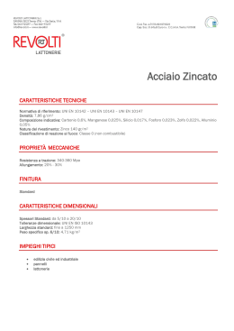
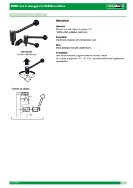
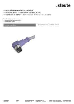
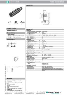
L8542138
Rev. 09/06/00
ASTA ARTICOLATA
ARTICULATED ROD
GEGLIEDERTE STANGE
TIGE ARTICULÉE
ASTA ARTICULADA
RAMIĘ PRZEGUBOWE
LADY.SN
Libro istruzioni
Operating instructions
Betriebsanleitung
Livret d’instructions
Manual de instrucciones
Książeczka z instrukcjami
UNIONE NAZIONALE COSTRUTTORI
AUTOMATISMI PER CANCELLI, PORTE,
SERRANDE ED AFFINI
LA
L2
72
44
L1
L3
820
L1
HT
Fig.1
2
102
240
44
50
Vite M12x70 UNI 5931.
Screw M12x70 UNI 5931.
Schraube M12x70 UNI 5931.
Vis M12x70 UNI 5931.
Tornillo M12x70 UNI 5931.
Śruba M12x70 UNI 5931.
Piastra.
Plate.
Platte.
Plaque.
Placa.
Płyta.
Vite M6x55 UNI 5931.
Screw M6x55 UNI 5931.
Schraube M6x55 UNI 5931.
Vis M6x55 UNI 5931.
Tornillo M6x55 UNI 5931.
Vite M8x16 UNI 5931.
Screw M8x16 UNI 5931.
Schraube M8x16 UNI 5931.
Vis M8x16 UNI 5931.
Tornillo M8x16 UNI 5931.
Śruba M8x16 UNI 5931.
Bussola.
Sleeve.
Buchsen.
Douille.
Articulación.
Tulejka.
Perno Ø12.
Pin Ø12.
Stift Ø12.
Tige Ø12.
Clavija Ø12.
Kołek Ø12.
Distanziale.
Spacer.
Distanzstück.
Entretoise.
Separador.
Przekładka.
Distanziale.
Spacer.
Distanzstück.
Entretoise.
Separador.
Przekładka.
Piastra.
Plate.
Platte.
Plaque.
Placa.
Płyta
Distanziale.
Spacer.
Distanzstück.
Entretoise.
Separador.
Przekładka
Dado autobloccante M6 UNI 7473.
Self locking nut M6 UNI 7473.
Selbstsperrende mutter M6 UNI 7473.
Écrou auto-bloquant M6 UNI 7473.
Tuerca autoblocante M6 UNI 7473.
Nakrętka samozabezpieczająca się M12 UNI 7473.
Supporto della bussola.
Sleeve support.
Buchsenhalter.
Support de la douille.
Soporte de la articulación.
Łożysko tulejki.
Dado autobloccante M12 UNI 7473.
Self locking nut M12 UNI 7473.
Selbstsperrende mutter M12 UNI 7473.
Écrou auto-bloquant M12 UNI 7473.
Tuerca autoblocante M12 UNI 7473.
Nakrętka samozabezpieczająca się M12 UNI 7473.
Vite M6x15 UNI 5931.
Screw M6x15 UNI 5931.
Schraube M6x15 UNI 5931.
Vis M6x15 UNI 5931.
Tornillo M6x15 UNI 5931.
Śruba M6x15 UNI 5931.
Vite M6x15 UNI 5931.
Screw M6x15 UNI 5931.
Schraube M6x15 UNI 5931.
Vis M6x15 UNI 5931.
Tornillo M6x15 UNI 5931.
Śruba M6x15 UNI 5931.
14
Vite M8x16 UNI 5931.
Screw M8x16 UNI 5931.
Schraube M8x16 UNI 5931.
Vis M8x16 UNI 5931.
Tornillo M8x16 UNI 5931.
Śruba M8x16 UNI 5931.
Testata sferica maschio M12.
Spheric head M12.
Kugelkopf M12.
Tête sphérique M12.
Cabeza esférica macho M12.
Głowica kulista M12.
75
72
10
Ø6.5 n° 2 fori passanti.
N° 2 holes Ø6.5.
2 Bohrungen Ø6.5.
N° 2 trous Ø6.5.
Ø6.5 2 agujeros pasantes.
Ø6.5 - 2 otwory przelotowe.
Ø6.5 n° 4 fori passanti.
N° 4 holes Ø6.5.
4 Bohrungen Ø6.5.
N° 4 trous Ø6.5.
Ø6.5 4 agujeros pasantes.
Ø6.5 - 4 otwory przelotowe.
10
45
Fig.2
3
Piastra di movimento.
Movement plate.
Platte.
Plaque.
Placa de movimiento.
Płyta ruchu.
Dado M12 UNI 5588.
Nut M12 UNI 5588.
Mutter M12 UNI 5588.
Ecrou M12 UNI 5588.
Tuerca M12 UNI 5588.
Nakrętka M12 UNI 5588.
Distanziale.
Spacer.
Distanzstück.
Entretoise.
Separadores.
Przekładka
Tirante.
Rod.
Zugstange.
Tirant.
Tirante.
Odciąg
Testata sferica maschio M12.
Spheric head M12.
Kugelkopf M12.
Tête sphérique M12.
Cabeza esférica macho M12.
Głowica kulista M12.
Dado da premontare M12 sinistro.
Preset nut M12.
Vorzumontierende Mutter M12.
Ecrou prémonté M12.
Tuerca para premontar M12 izquierda.
Nakrętka do montażu wstępnego M12 lewego.
Testata sferica maschio M12 sinistro.
Spheric head M12.
Kugelkopf M12.
Tête sphérique M12.
Cabeza esférica macho M12 izquierda.
Głowica kulista M12 lewa.
Vite M8x16 UNI 5931.
Screw M8x16 UNI 5931.
Schraube M8x16 UNI 5931.
Vis M8x16 UNI 5931.
Tornillo M8x16 UNI 5931.
Śruba M8x16 UNI 5931.
Rosetta 8.4x17 UNI 6592.
Washer 8.4x17 UNI 6592.
Unterlegscheibe 8.4x17 UNI 6592.
Rondelle 8.4x17 UNI 6592.
Arandela 8.4x17 UNI 6592.
Nakrętka 8.4x17 UNI 6592.
Perno da avvitare sul cassone.
Journal to be threaded on the box.
An den Kasten zu schraubender Stift.
Tige à visser sur le caisson.
Placa para atornillar sobre el armario.
Trzpień do wkręcenia na skrzyni.
Fig.3
4
•
Istruzioni di montaggio
Calcolare la lunghezza dei due spezzoni d’asta e del tirante con le formule:
LA=L1+L2+174
L1=HT-870
L2=LA-(L1+174)
L3=L1-120
N.B. HT max= 294 cm
•
•
•
•
•
•
•
•
•
•
•
facendo riferimento alla fig. 1.
Tagliare a misura e forare i due spezzoni d’asta secondo le misure di fig. 2.
Tagliare il tirante a misura L3 (N.B.: una estremità è già filettata M14 sx). Filettare M12 l’estremità appena
tagliata.
Forare e filettare M12 il cassone secondo le quote di Fig.1 a seconda della versione Dx o Sx.
Montare le testate sferiche sul tirante (dopo avervi premontato i dadi) fig. 3.
Avvitare il perno filettato sul cassone (fig. 3), inserirvi la testata sferica e serrare la vite.
Assemblare le due piastre sul profilo di lunghezza L2 senza bloccare le viti (fig. 2).
Inserire il supporto della bussola nel profilo di lunghezza L1 e bloccare le viti (fig. 2).
Fissare il profilo L1 alla piastra di movimento (fig. 3).
Fissare il tirante, interponendo i distanziali, tra le due piastre con la vite M12 (fig. 3).
Inserire il perno Ø12 nel supporto e fissarlo con le due viti M8 (fig. 2).
Agendo ora sul tirante regolare l’orizzontalità del profilo L2.
Serrare forte i due dadi delle testate sferiche contro il tirante.
Serrare infine le viti M6 che fissano le piastre allo spezzone L2.
•
Calculate the length of the two rod parts and of the stay bolt by using the formulas
•
•
Assembling instructions
LA=L1+L2+174
L1=HT-870
L2=LA-(L1+174)
L3=L1-120
•
•
•
•
•
•
•
•
•
•
•
•
•
N.B. HT max=294 cm
and referring to fig. 1.
Cut to length and bore the two rod pieces as per measurements given in fig. 2.
Cut to length the stay bolt L3 (P.N. One end is already threaded M14). Thread M12 the end just
cut.
The casing should be drilled and threaded M12 according to figures shown in Fig. 1 and taking in
to account whether the model features a right or left fitting.
Fit the spheric round heads on the stay bolt (after presetting the nuts) fig. 3.
Screw the threaded journal on the box (fig. 3), insert the spheric head and tighten the screw.
Assemble the two plates on length L2 without tightening the screws (fig. 2).
Insert the sleeve support in the length L1 and fix the screw (fig. 2).
Fix the profile L1 to the movement plate (fig. 3).
Fix the stay bolt (placing the spacers between), between the plates, through the screw M12
(fig. 3).
Insert the Ø 12 mm pin in the support and secure it with two M8 screws (fig. 2).
Level now the profile L2 through the stay bolt
Tighten the 2 nuts of the spheric heads against the stay bolt.
Tighten the screws M6 which secure the plates to the L2 piece.
5
Montageanweisungen
•
Unter Bezugnahme auf Bild 6 berechnen Sie die Länge der zwei Stangenteilstücke und der Zugstange
mit der Formel
LA = L1+L2+174
L1 = HT+870
L2 = LA - (L1+174)
L3 = L1-120
•
•
•
•
Abb. 1:
Die zwei Stangenstücke nach den Maßen auf Bild 2 maßschneiden und bohren.
Zustange maßschneiden (Länge L3). Ein Ende ist schon M14 links gewindegeschnitten.
Das soeben geschnittene Ende M12 gewindeschneiden.
Löcher in den Kasten entsprechend den Maßen in Abb. 1 bohren und die Gewinde schneiden (M12) je
nach dem ob es sich um die rechte oder linke Ausführung handelt.
Kugelköpfe an der Zugstange anbringen, nachdem dort die Muttern vormontiert worden sind (Bild 3).
Gewindestift an den Kasten schrauben (Bild 3), Kugelkopf einfügen und Schraube anziehen.
Die zwei Platten an dem Längenprofil L2 zusammenfügen, ohne die Schrauben zu sperren (Bild 2).
Den Buchsenhalter in das Längsprofil L1 einführen und die Schrauben anziehen (Bild 2).
Profil L1 an der Bewegungsplatte befestigen (Bild 3).
Zugstange befestigen und Distanzstücke zwischen beiden Platten mit Schraube M12 befestigen (Bild
3).
Stift Ø 12 im Halter mit den beiden Schrauben M8 befestigen (Bild 3).
Nun die Zugstange betätigen und die waagerechte Lage des Profils L2 regulieren.
Beide Muttern der Kugelköpfe fest an die Zugstange schrauben.
Die Schrauben M6, die die Platten an dem Teilstück L2 befestigen, anziehen.
•
Calculer la longueur des deux morceaux de tige et du tirant avec les formules:
•
•
•
•
•
•
•
•
•
Instructions de montage
LA = L1+L2+174
L1 = HT+870
L2 = LA - (L1+174)
L3 = L1-120
•
•
•
•
•
•
•
•
•
•
•
•
•
6
N.B. HT max= 294 cm.
N.B. HT max= 294 cm
en vous référant à la Fig. 1.
Couper aux bonnes dimensions et percer les deux morceaux de tige selon les meures de la Fig.
2.
Couper le tirant à la dimension L3 (N.B. : une extrémité est déjà filetée M12 gauche).
Fileter M12 l’extrémité qui vient d’être coupée.
Percez et filetez M12 le caisson suivant les cotes de la Fig.1 selon la version Dx ou Sx.
Monter les têtes sphériques sur le tirant (après que vous ayez préalablement monté les écrous)
Fig. 3.
Visser la tige filetée sur le caisson (Fig. 3), puis insérer la tête sphérique et serrer la vis.
Assembler les deux plaques sur le profil de longueur L2 sans bloquer les vis (fig. 2).
Insérer le support de la douille dans le profil de longueur L1 et bloquer les vis (fig. 2).
Fixer le profil L1 à la plaque de mouvement (Fig. 3).
Fixer le tirant, en interposant les entretoises entre les deux plaques avec la vis M12 (fig. 3).
Insérer la tige Ø12 sur le support et la fixer avec les deux vis M8 (fig. 2).
En agissant sur le tirant régler l’horizontalité du profil L2.
Serrer fort les deux écrous des têtes sphériques contre le tirant.
Serrer enfin les vis M6 qui fixent les plaques à la partie L2.
•
Instrucciones de montaje
Calcular la longitud de las dos piezas del asta y del tirante con las fórmulas:
LA=L1+L2+174
L1=HT-870
L2=LA-(L1+174)
L3=L1-120
N.B. HT max = 294 cm.
•
•
•
•
•
•
•
•
•
•
haciendo referencia con la fig. 1.
Cortar a medida y agujerear las dos piezas del asta según las medidas de la fig. 2.
Cortar el tirante a medida L3 (NOTA: un extremo está ya roscado M12 sx). Roscar M12 el extremo recién
cortado.
Taladrar y roscar M12 la caja ajustándose a las cotas de la Fig.1 según la versión Derecha o Izquierda.
Montar las cabezas esféricas sobre el tirante (después de haber montado las tuercas) fig. 3.
Atornillar el perno roscado sobre el armario (fig. 3), insertarle la cabeza esférica y apretar el tornillo.
Ensamblar las dos placas sobre el perfil de longitud L2 sin bloquear los tonillos (fig. 2).
Insertar el soporte de la articulación en el perfil de longitud L1 y apretar los tornillos (fig. 2).
Fijar el perfil L1 a la placa de movimiento (fig. 3).
Fijar el tirante, interponiendo los separadores entre las placas con el tornillo M12 (fig. 3).
Insertar el perno Ø12 en el soporte y fijarlo con los dos tornillos M8 (fig. 2).
Operando ahora sobre el tirante regular la horizontalidad del perfil L2.
Apretar fuerte las dos tuercas de la cabeza esférica contra el tirante.
Apretar finalmente los tornillos M6 que fijan las placas a la pieza L2.
•
Obliczyć długość dwu odcinków ramienia i odciągu według niżej podanych wzorów:
•
•
•
Instrukcja montażu
LA=L1+L2+174
L1=HT-870
L2=LA-(L1+174)
L3=L1-120
•
•
•
•
•
•
•
•
•
•
•
•
•
N.B. HT max= 294 cm
zgodnie ze wskazówkami na Rys. 1.
Odciąć dwie części ramienia o odpowiedniej długości i wykonać odwierty według wymiarów podanych
na Rys. 2.
Odciąć odcinek odciągu według wymiaru L3 (N.B.: jeden koniec jest gwintowany M14 sx). Wykonać
gwintowanie M12 na odciętym końcu.
Wykonać otwór i nagwintować M12 na skrzyni zgodnie z wymiarami podanymi na Rys.1 w zależności
od wersji Dx lub Sx (prawa lub lewa).
Zamontować głowice kuliste na odciągu (po wcześniejszym wstępnym zamocowaniu nakrętki) Rys. 3.
Wkręcić trzpień gwintowany do skrzyni (Rys. 3), wprowadzić głowicę kulistą i dokręcić śrubę.
Zamontować dwie płyty na listwie o długości L2 bez zamocowania śrub (Rys. 2).
Wprowadzić łożysko tulejki do listwy o długości L1 i zamocować śruby (Rys. 2).
Przymocować listwę L1 do płyty ruchomej tak (Rys. 3).
Zamocować odciąg, zakładając przekładki między dwiema płytami ze śrubami M12 (Rys. 3).
Wprowadzić trzpień Ø12 do łożyska i zamocować go dwiema śrubami M8 (Rys. 2).
Przy pomocy odciągu wyregulować wypoziomowanie listwy L2.
Dokładnie dokręcić dwie nakrętki głowic kulistych przeciw odciągowi.
Na koniec dokręcić śruby M6 mocujące płyty do odcinka L2.
7
AUTOMATISMI BENINCÀ SpA - Via Capitello, 45 - 36066 Sandrigo (VI) - Tel. 0444 751030 r.a. - Fax 0444 759728
Scarica