PROBLEMS
283
PROBLEMS - Cap. 8 - Sistemi di I/O
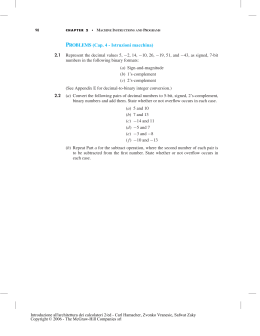
4.1
The input status bit in an interface circuit is cleared as soon as the input data buffer is
read. Why is this important?
4.2
Write a program that displays the contents of 10 bytes of the main memory in hexadecimal format on a video display. Use either the assembler instructions of a processor
of your choice or pseudo-instructions. Start at location LOC in the memory, and use
two hex characters per byte. The contents of successive bytes should be separated by a
space.
4.3
The address bus of a computer has 16 address lines, A15−0 . If the address assigned to
one device is 7CA416 and the address decoder for that device ignores lines A8 and A9 ,
what are all the addresses to which this device will respond?
4.4
What is the difference between a subroutine and an interrupt-service routine?
4.5
The discussion in this chapter assumed that interrupts are not acknowledged until the
current machine instruction completes execution. Consider the possibility of suspending operation of the processor in the middle of executing an instruction in order to
acknowledge an interrupt. Discuss the difficulties that may arise.
4.6
Three devices, A, B, and C, are connected to the bus of a computer. I/O transfers for all
three devices use interrupt control. Interrupt nesting for devices A and B is not allowed,
but interrupt requests from C may be accepted while either A or B is being serviced.
Suggest different ways in which this can be accomplished in each of the following cases:
(a) The computer has one interrupt-request line.
(b) Two interrupt-request lines, INTR1 and INTR2, are available, with INTR1 having
higher priority.
Specify when and how interrupts are enabled and disabled in each case.
Introduzione all'architettura dei calcolatori 2/ed - Carl Hamacher, Zvonko Vranesic, Safwat Zaky
Copyright © 2006 - The McGraw-Hill Companies srl
284
CHAPTER 4
•
INPUT/OUTPUT ORGANIZATION
4.7
Consider a computer in which several devices are connected to a common interruptrequest line, as in Figure 4.8a. Explain how you would arrange for interrupts from
device j to be accepted before the execution of the interrupt-service routine for device i
is completed. Comment in particular on the times at which interrupts must be enabled
and disabled at various points in the system.
4.8
Consider the daisy chain arrangement in Figure 4.8a. Assume that after a device generates an interrupt request, it turns off that request as soon as it receives the interruptacknowledge signal. Is it still necessary to disable interrupts in the processor before
entering the interrupt-service routine? Why?
4.9
4.10
A computer is required to accept characters from 20 video terminals. The main memory
area to be used for storing data for each terminal is pointed to by a pointer PNTRn,
where n = 1 through 20. Input data must be collected from the terminals while another
program PROG is being executed. This may be accomplished in one of two ways:
(a) Every T seconds, program PROG calls a polling subroutine POLL. This subroutine
checks the status of each of the 20 terminals in sequence and transfers any input
characters to the memory. Then it returns to PROG.
(b) Whenever a character is ready in any of the interface buffers of the terminals, an
interrupt request is generated. This causes the interrupt routine INTERRUPT to
be executed. After polling the status registers, INTERRUPT transfers the input
character and then returns to PROG.
Write the routines POLL and INTERRUPT using either pseudocode or the assembler
language of the processor of your choice. Let the maximum character rate for any
terminal be c characters per second, with an average rate equal to rc, where r ≤ 1. In
method (a), what is the maximum value of T for which it is still possible to guarantee
that no input characters will be lost? What is the equivalent value for method (b)?
Estimate, on the average, the percentage of time spent in servicing the terminals for
methods (a) and (b), for c = 100 characters per second and r = 0.01, 0.1, 0.5, and 1.
Assume that POLL takes 800 ns to poll all 20 devices and that an interrupt from a
device requires 200 ns to process.
Introduzione all'architettura dei calcolatori 2/ed - Carl Hamacher, Zvonko Vranesic, Safwat Zaky
Copyright © 2006 - The McGraw-Hill Companies srl
PROBLEMS
4.11
285
Consider an I/O device that uses the vectored-interrupt capability of the 68000
processor.
(a) Describe the sequence of steps that take place when the processor receives an
interrupt request, and give the number of bus transfers required during each of
these steps. Do not give details of bus signals or the microprogram.
(b) When an interrupt request is received, the processor completes execution of the
current instruction before accepting the interrupt. Examine the instruction table in
Appendix C, and estimate the maximum possible number of memory transfers that
can take place during that period.
(c) Estimate the number of bus transfers that can occur from the instant a device requests
an interrupt until the first instruction of the interrupt-service routine is fetched for
execution.
4.12
A logic circuit is needed to implement the priority network shown in Figure 4.8b. The
network handles three interrupt request lines. When a request is received on line INTRi,
the network generates an acknowledgment on line INTAi. If more than one request is
received, only the highest-priority request is acknowledged, where the ordering of
priorities is
priority of INTR1 > priority of INTR2 > priority of INTR3
(a)
(b)
(c)
(d)
Give a truth table for each of the outputs INTA1, INTA2, and INTA3.
Give a logic circuit for implementing this priority network.
Can your design be easily extended for more interrupt-request lines?
By adding inputs DECIDE and RESET, modify your design such that INTAi is set
to 1 when a pulse is received on the input DECIDE and is reset to 0 when a pulse
is received on the input RESET.
4.13
Interrupts and bus arbitration require means for selecting one of several requests based
on their priority. Design a circuit that implements a rotating-priority scheme for four
input lines, REQ1 through REQ4. Initially, REQ1 has the highest and REQ4 the lowest
priority. After some line receives service, it becomes the lowest priority line, and the
next line receives highest priority. For example, after REQ2 has been serviced, the
priority order, starting with the highest, becomes REQ3, REQ4, REQ1, REQ2. Your
circuit should generate four output grant signals, GR1 through GR4, one for each input
request line. One of these outputs should be asserted when a pulse is received on a line
called DECIDE.
4.14
The 68000 processor has a set of three lines called IPL2–0 that are used to signal
interrupt requests. The 3-bit binary number on these lines is interpreted by the processor
as representing the highest-priority device requesting an interrupt. Design a priority
encoder circuit that accepts interrupt requests from as many as seven devices and
generates a 3-bit code representing the request with the highest priority.
4.15
(This problem is suitable for use as a laboratory experiment.) Given a video terminal
connected to the computer in your laboratory, complete the following two assignments.
Introduzione all'architettura dei calcolatori 2/ed - Carl Hamacher, Zvonko Vranesic, Safwat Zaky
Copyright © 2006 - The McGraw-Hill Companies srl
286
CHAPTER 4
•
INPUT/OUTPUT ORGANIZATION
(a) Write an I/O routine A that prints letters in alphabetical order. It prints two lines as
follows, and then stops:
ABC . . . YZ
ABC . . . YZ
(b) Write an I/O routine B that prints the numeric characters 0 through 9 in increasing
order three times. Its output should have the following format:
012 . . . 9012 . . . 9012 . . . 9
Use program A as the main program and program B as an interrupt-service routine
whose execution is initiated by entering any character on the keyboard. Execution of
program B can also be interrupted by entering another character on the keyboard. When
program B is completed, execution of the most recently interrupted program should be
resumed at the point of interruption. Program B should start a new line as appropriate
so that the printed output may appear as follows:
ABC
012 . . . 901
012 . . . 9012 . . . 9012 . . . 9
2. . . 9012 . . . 9
DE . . . YZ
To start a new line, the program needs to send two characters: CR (0D16 ) and LF (0A16 ).
Show how you can use the processor priority to either enable or inhibit interrupt nesting.
4.16
(This problem is suitable for use as a laboratory experiment.) In Problem 4.15, when
the printing of a sequence is interrupted and later resumed, the sequence continues at
the beginning of a new line. It is desired to add cursor movement control functions
such that when printing of a sequence is resumed, the characters are printed on a new
line, at the same character position where they would have been had the interruption
not occurred. Thus, the printed output would appear as follows:
ABC
012 . . . 901
012 . . . 9012 . . . 9012 . . . 9
2 . . . 9012 . . . 9
DE . . . YZ
Rearrange the software you prepared in Problem 4.15 so that a third controller routine,
C, is entered when interruption occurs. This routine calls program B to print the number
sequence. Then, before returning to the interrupted program, the routine issues cursor
movement commands as appropriate.
4.17
Consider the breakpoint scheme described in Section 4.2.5. A software-interrupt instruction replaces a program instruction where the breakpoint is inserted. Before it
returns to the original program, the debugging software puts the original program
Introduzione all'architettura dei calcolatori 2/ed - Carl Hamacher, Zvonko Vranesic, Safwat Zaky
Copyright © 2006 - The McGraw-Hill Companies srl
287
PROBLEMS
instruction back in its place, thus removing the breakpoint. Explain how the debugger
can put the original program instruction in its place, execute it, then install the breakpoint
again before any other program instruction is executed.
4.18
4.19
The interrupt-request line, which uses the open-collector scheme, carries a signal that
is the logical OR of the requests from all the devices connected to it. In a different
application, it is required to generate a signal that indicates that all devices connected
to the bus are ready. Explain how you can use the open-collector scheme for this purpose.
4.20
In some computers, the processor responds only to the leading edge of the interruptrequest signal on one of its interrupt-request lines. What happens if two independent
devices are connected to this line?
4.21
In the arrangement in Figure 4.20, a device becomes the bus master only when it receives
a low-to-high transition on its bus grant input. Assume that device 1 requests the bus
and receives a grant. While it is still using the bus, device 3 asserts its BR output. Draw
a timing diagram showing how device 3 becomes the bus master after device 1 releases
the bus.
4.22
Assume that in the bus arbitration arrangement in Figure 4.20, the processor keeps
asserting BG1 as long as BR is asserted. When device i is requesting the bus, it becomes
the bus master only when it receives a low-to-high transition on its BGi input.
4.23
(a) Assume that devices are allowed to assert the BR signal at any time. Give a sequence
of events to show that the system can enter a deadlock situation, in which one or
more devices are requesting the bus, the bus is free, and no device can become the
bus master.
(b) Suggest a rule for the devices to observe in order to prevent this deadlock situation
from occurring.
Consider the daisy-chain arrangement shown in Figure P4.1, in which the bus-request
signal is fed back directly as the bus grant. Assume that device 3 requests the bus and
BG1
BG2
BR1
BGn
BR2
Figure P4.1 A decentralized bus assignment scheme.
Introduzione all'architettura dei calcolatori 2/ed - Carl Hamacher, Zvonko Vranesic, Safwat Zaky
Copyright © 2006 - The McGraw-Hill Companies srl
BRn
288
CHAPTER 4
•
INPUT/OUTPUT ORGANIZATION
begins using it. When device 3 is finished, it deactivates BR3. Assume that the delay
from BGi to BG(i + 1) in any device is d. Show that a spurious bus grant pulse will
travel downstream from device 3 (spurious because it is not a response to any request).
Estimate the width of this pulse.
4.24
Shortly after device 3 in Problem 4.23 releases the bus, devices 1 and 5 request the bus
simultaneously. Show that they can both receive a bus grant.
4.25
Consider the bus arbitration scheme shown in Figure 4.20. Assume that a local signal
called BUSREQ in the device interface circuit is equal to 1 whenever the device needs
to use the bus. Design the part of the interface circuit that has BUSREQ, BGi, and
BBSY as inputs and that generates BR, BG(i + 1), and BBSY as outputs.
4.26
Consider the arbitration circuit shown in Figure 4.22. Assume that the priority code for a
device is stored in a register in the interface circuit. Design a circuit to implement this arbitration scheme. Arbitration begins when Start-Arbitration is asserted. A little later, the
arbitration circuit should activate an output called Winner if it wins the arbitration cycle.
4.27
How would the timing diagram in Figure 4.26 be affected if the distance between the
processor and the I/O device is increased? How can this increased distance be accommodated in the case of Figure 4.24?
4.28
An industrial plant uses several limit sensors for monitoring temperature, pressure, and
other factors. The output of each sensor consists of an ON/OFF switch, and eight such
sensors need to be connected to the bus of a small computer. Design an appropriate
interface so that the state of all eight switches can be read simultaneously as a single
byte at address FE1016 . Assume the bus is synchronous and that it uses the timing
sequence of Figure 4.24.
4.29
Design an appropriate interface for connecting a seven-segment display as an output
device on a synchronous bus. (See Figure A.37 in Appendix A for a description of a
seven-segment display.)
4.30
Add an interrupt capability to the interface in Figure 4.29. Show how you can introduce
an interrupt-enable bit, which can be set or cleared by the processor as bit 6 of the status
register of the interface. The interface should assert an interrupt request line, INTR,
when interrupts are enabled and input data are available to be read by the processor.
4.31
The bus of a processor uses the multiple-cycle scheme described in Section 4.5.1. The
speed of a memory unit is such that a read operation follows the timing diagram shown
in Figure 4.25. Design an interface circuit to connect this memory unit to the bus.
4.32
Consider a write operation on a bus that uses the multiple-cycle scheme described in
Section 4.5.1. Assume that the processor can send both address and data in the first
clock cycle of a bus transaction. But the memory requires two clock cycles after that
to store the data.
(a) Can the bus be used for other transactions during that period?
(b) Can we do away with the memory’s response in this case? (Hint: Examine carefully
the case in which the processor attempts another write operation to the same memory
module while that module is still busy completing a previous request. Explain how
this situation can be handled.)
Introduzione all'architettura dei calcolatori 2/ed - Carl Hamacher, Zvonko Vranesic, Safwat Zaky
Copyright © 2006 - The McGraw-Hill Companies srl
4.33
Figures 4.24 to 4.26 provide three different approaches to bus design. What happens
in each case if the addressed device does not respond due to a malfunction? What
problems would this cause and what remedies are possible?
4.34
In the timing diagram in Figure 4.25, the processor maintains the address on the bus
until it receives a response from the device. Is this necessary? What additions are needed
on the device side if the processor sends an address for one cycle only?
4.35
Consider a synchronous bus that operates according to the timing diagram in Figure 4.24. The address transmitted by the processor appears on the bus after 4 ns. The
propagation delay on the bus wires between the processor and different devices connected varies from 1 to 5 ns, address decoding takes 6 ns, and the addressed device
takes between 5 and 10 ns to place the requested data on the bus. The input buffer needs
3 ns of setup time. What is the maximum clock speed at which this bus can operate?
4.36
The time required for a complete bus transfer in the case of Figure 4.26 varies depending
on the delays involved. Consider a bus having the same parameters as in Problem 4.35.
What is the minimum and maximum bus cycle time?
Introduzione all'architettura dei calcolatori 2/ed - Carl Hamacher, Zvonko Vranesic, Safwat Zaky
Copyright © 2006 - The McGraw-Hill Companies srl
Chapter 4 – Input/Output Organization
4.1. After reading the input data, it is necessary to clear the input status ag before
the program begins a new read operation. Otherwise, the same input data would
be read a second time.
4.2. The ASCII code for the numbers 0 to 9 can be obtained by adding $30 to the
number. The values 10 to 15 are represented by the letters A to F, whose ASCII
codes can be obtained by adding $37 to the corresponding binary number.
Assume the output status bit is
is Output.
Next
Convert
Letters
Print
in register Status, and the output data register
Move
Move
Move
Move
Shift-right
Call
Move
Call
Move
Call
Increment
Decrement
Branch 0
End
#10,R0
#LOC,R1
(R1),R2
R2,R3
#4,R3
Convert
R2,R3
Convert
$20,R3
Print
R1
R0
Next
Use R0 as counter
Use R1 as pointer
Get next byte
And
Compare
Branch 0
Or
Branch
Add
BitTest
Branch 0
Move
Return
#0F,R3
#9,R3
Letters
#$30,R3
Print
#$37,R3
#4,Status
Print
R3,Output
Keep only low-order 4 bits
Prepare bits
Prepare bits
-
Print space
Repeat if more bytes left
Branch if [R3] 9
Convert to ASCII, for values 0 to 9
Convert to ASCII, for values 10 to 15
Test output status bit
Loop back if equal to 0
Send character to output register
4.3. 7CA4, 7DA4, 7EA4, 7FA4.
4.4. A subroutine is called by a program instruction to perform a function needed by
the calling program. An interrupt-service routine is initiated by an event such as
an input operation or a hardware error. The function it performs may not be at
1
Introduzione all'architettura dei calcolatori 2/ed - Carl Hamacher, Zvonko Vranesic, Safwat Zaky
Copyright © 2006 - The McGraw-Hill Companies srl
all related to the program being executed at the time of interruption. Hence, it
must not affect any of the data or status information relating to that program.
4.5. If execution of the interrupted instruction is to be completed after return from
interrupt, a large amount of information needs to be saved. This includes the
contents of any temporary registers, intermediate results, etc. An alternative is
to abort the interrupted instruction and start its execution from the beginning
after return from interrupt. In this case, the results of an instruction must not be
stored in registers or memory locations until it is guaranteed that execution of
the instruction will be completed without interruption.
4.6. (a) Interrupts should be enabled, except when C is being serviced. The nesting
rules can be enforced by manipulating the interrupt-enable ags in the interfaces
of A and B.
(b) A and B should be connected to INTR , and C to INTR . When an interrupt
request is received from either A or B, interrupts from the other device will be
automatically disabled until the request has been serviced. However, interrupt
requests from C will always be accepted.
_
4.7. Interrupts are disabled before the interrupt-service routine is entered. Once device turns off its interrupt request, interrupts may be safely enabled in the processor. If the interface circuit of device turns off its interrupt request when it_
receives the interrupt acknowledge signal, interrupts may be enabled at the beginning of the interrupt-service routine of device . Otherwise, interrupts may
be enabled only after the instruction that causes device to turn off its interrupt
request has been executed.
4.8. Yes, because other devices may keep the interrupt request line asserted.
4.9.
Introduzione all'architettura dei calcolatori 2/ed - Carl Hamacher, Zvonko Vranesic, Safwat Zaky
Copyright © 2006 - The McGraw-Hill Companies srl
BLK-FULL: A binary variable, indicating whether a block is full and ready for
processing.
IN-COUNT: Number of characters read.
IN-POINTER: Points at the location where the next input character is to be
stored.
PROG-BLK: Points at the location of the block to be processed by PROG.
Two memory buffers are needed, each capable of storing a block of data. Let
BLK(0) and BLK(1) be the addresses of the two memory buffers. The structure
of CONTROL and INPUT can be described as follows.
CONTROL
BLK-FULL := false
IN-POINTER := BLK( )
IN-COUNT := 0
Enable interrupts
:= 0
Loop
Wait for BLK-FULL
If not last block then BLK-FULL := false
Prepare to read the next block
IN-POINTER := BLK( )
IN-COUNT := 0
Enable interrupts PROG-BLK := BLK( )
Process the block just read
Call PROG
If last block then exit
End Loop
Interrupt-service routine
INPUT:
Store input character and increment IN-COUNT and IN-POINTER
If IN-COUNT = N Then disable interrupts from device
BLK-FULL := true Return from interrupt
4.10. Correction: In the last paragraph, change “equivalent value” to “equivalent
condition”.
Assume that the interface registers for each video terminal are the same as in
Figure 4.3. A list of device addresses is stored in the memory, starting at DEVICES, where the address given in the list, DEVADRS, is that of DATAIN. The
pointers to data areas, PNTR , are also stored in a list, starting at PNTRS.
Note that depending on the processor, several instructions may be needed to
perform the function of one of the instructions used below.
3
Introduzione all'architettura dei calcolatori 2/ed - Carl Hamacher, Zvonko Vranesic, Safwat Zaky
Copyright © 2006 - The McGraw-Hill Companies srl
POLL
LOOP
NXTDV
INTERRUPT
Move
Move
BitTest
Branch 0
Move
MoveByte
Move
Decrement
Branch 0
Return
#20,R1
DEVICES(R1),R2
#0,2(R2)
NXTDV
PNTRS(R1),R3
(R2),(R3)+
R3,PNTRS(R1)
R1
LOOP
Use R1 as device counter, Get address of device Test input status of a device
Skip read operation if not ready
Get pointer to data for device Get and store input character
Update pointer in memory
Same as POLL, except that it returns once a character
is read. If several devices are ready at the same time,
the routine will be entered several times in succession.
In case a, POLL must be executed at least 100 times per second. Thus ms.
!"
The equivalent condition for case b can be obtained by considering the case when
all 20 terminals become ready at the same time. The time required for interrupt
servicing must be less than the inter-character delay. That is, #$&%'#(()%*,+.-0/
21(3 , or 34/5#(6$879$( char/s.
The time spent servicing the terminals in each second is given by:
Case a: Time :(;%*<$(;%=",+>- ns ?<(A@ s
Case b: Time B#$C%EDC%*#$(;%=",+>-F%G(FH($ID ns
Case b is a better strategy for D*/5KJ # .
The reader may repeat this problem using a slightly more complete model in
which the polling time, L , for case M is a function of the number of terminals.
For example, assume that L increases by 0.5 @ s for each terminal that is ready,
that is, LNO#$)P#$IDQ%Q8J 6 .
4.11.
(a) Read the interrupt vector number from the device (1 transfer).
Save PC and SR (3 transfers on a 16-bit bus).
Read the interrupt vector (2 transfers) and load it in the PC.
(b) The 68000 instruction requiring the maximum number of memory transfers
is:
MOVEM.L D0-D7/A0-A7,LOC.L
where LOC.L is a 32-bit absolute address. Four memory transfers are
needed to read the instruction, followed by 2 transfers for each register,
for a total of 36.
(c) 36 for completion of current instruction plus 6 for interrupt handling, for a
total of 42.
4.12.
(a)
RTSVUXWE&RTSVUAYE
RTSVUXWV#;RTSVUAYV#)Z RTSVUAYE
RTSVUXWV[;RTSVUAYV[)Z RTSVUAYEBZ RTS0UAY\#
4
Introduzione all'architettura dei calcolatori 2/ed - Carl Hamacher, Zvonko Vranesic, Safwat Zaky
Copyright © 2006 - The McGraw-Hill Companies srl
(b) See logic equations in part a.
(c) Yes.
_
(d) In the circuit below, DECIDE is used to lock interrupt requests. The processor should set the interrupt acknowledge signal, INTA, after DECIDE
returns to zero. This will cause the highest priority request to be acknowledged. Note that latches are placed at the inputs of the priority circuit.
They could be placed at the outputs, but the circuit would be less reliable
when interrupts change at about the same time as arbitration is taking place
(races may occur).
INTR1
f
a
INTA1
INTR2
h
_
g
b
]
e
INTA2
INTR3
`
DECIDE
c
^
Reset
d
INTA3
INTA
4.13. In the circuit given below, register A records which device was given a grant
most recently. Only one of its outputs is equal to 1 at any given time, identifying
the highest-priority line. The falling edge of DECIDE records the results of
the current arbitration cycle in A and at the same time records new requests in
register B. This prevents requests that arrive later from changing the grant.
The circuit requires careful initialization, because one and only one output of
register A must be equal to 1. This output determines the highest-priority line
during a given arbitration cycle. For example, if the LSB of A is equal to 1, point
E2 will be equal to 0, giving REQ2 the highest priority.
5
Introduzione all'architettura dei calcolatori 2/ed - Carl Hamacher, Zvonko Vranesic, Safwat Zaky
Copyright © 2006 - The McGraw-Hill Companies srl
_
_
_
A
DECIDE
E1
GR1
REQ1
E2
GR2
REQ2
B
E3
GR3
REQ3
E4
GR4
REQ4
DECIDE
4.14. The truth table for a priority encoder is given below.
1
0
1
x
x
x
x
x
x
2
0
0
1
x
x
x
x
x
3
0
0
0
1
x
x
x
x
4
0
0
0
0
1
x
x
x
5
0
0
0
0
0
1
x
x
6
0
0
0
0
0
0
1
x
7
0
0
0
0
0
0
0
1
IPL
0
0
0
0
1
1
1
1
IPL 0
0
1
1
0
0
1
1
IPL
0
1
0
1
0
1
0
1
A possible implementation for this priority circuit is as follows:
6
Introduzione all'architettura dei calcolatori 2/ed - Carl Hamacher, Zvonko Vranesic, Safwat Zaky
Copyright © 2006 - The McGraw-Hill Companies srl
RTikjlmn
RTikj n q
RTikj
n
Pnpo0PGnpqVPn
Pn
Pn o
P
RTirj ps n Z"n q
P
ut
PGn
RTirj us n
PGn Z"n t
4.15. Assume that the interface registers are the same as in Figure 4.3 and that the
characters to be printed are stored in the memory.
* Program A (MAIN) points to the character string and calls DSPLY twice
MAIN
MOVE.L
#ISR,VECTOR Initialize interrupt vector
ORI.B
#$80,STATUS
Enable interrupts from device
MOVE
#$2300,SR
Set interrupt mask to 3
MOVEA.L #CHARS,A0
Set pointer to character list
BSR
DSPLY
MOVEA.L #CHARS,A0
BSR
DSPLY
END
MAIN
* Subroutine DSPLY prints the character string pointed to by A0
* The last character in the string must be the NULL character
DSPLY
...
RTS
* Program B, the interrupt-service routine, points at the number string and calls DSPLY
ISR
MOVEM.L A0, (A7)
Save registers used
MOVE.L
NEWLINE,A0 Start a new line
BSR
DSPLY
MOVEA.L #NMBRS,A0
Point to the number string
BSR
DSPLY
MOVEM.L (A7)+,A0
Restore registers
RTE
* Characters and numbers to be displayed
CHARS
CC
/AB . . . Z/
NEWLINE CB
$0D, $0A, 0
Codes for CR, LF and Null
NMBRS
CB
$0D, $0A
CC
/01 . . . 901 . . . 901 . . . 9/
CB
$0D, $0A, 0
When ISR is entered, the interrupt mask in SR is automatically set to 4 by the
hardware. To allow interrupt nesting, the mask must be set to 3 at the beginning
of ISR.
4.16. Modify subroutine DSPLY in Problem 4.15 to keep count of the number of characters printed in register D1. Before ISR returns, it should call RESTORE, which
sends a number of space characters (ASCII code 20 vq ) equal to the count in D1.
7
Introduzione all'architettura dei calcolatori 2/ed - Carl Hamacher, Zvonko Vranesic, Safwat Zaky
Copyright © 2006 - The McGraw-Hill Companies srl
DSPLY
RESTORE
LOOP
TEST
...
MOVE
MOVEB
ADDQ
MOVE
...
MOVE.L
BR
BTST
BEQ
MOVEB
DBRA
RTS
#$2400,SR
D0,DATAOUT
#1,D1
#$2300,SR
Disable keyboard interrupts
Print character
Enable keyboard interrupts
D1,D2
TEST
#1,STATUS
LOOP
#$20,DATAOUT
D2,LOOP
Note that interrupts are disabled in DSPLY before printing a character to ensure
that no further interrupts are accepted until the count is updated.
4.17. The debugger can use the trace interrupt to execute the saved instruction then
regain control. The debugger puts the saved instruction at the correct address,
enables trace interrupts and returns. The instruction will be executed. Then, a
second interruption will occur, and the debugger begins execution again. The debugger can now remove the program instruction, reinstall the breakpoint, disable
trace interrupts, then return to resume program execution.
4.18.
(a) The return address, which is in register R14 svc, is PC+4, where PC is the
address of the SWI instruction.
LDR
BIC
R2,[R14,#-4]
R2,R2,#&FFFFFF00
Get SWI instruction
Clear high-order bits
(b) Assume that the low-order 8 bits in SWI have the values 1, 2, 3, ... to
request services number 1, 2, 3, etc. Use register R3 to point to a table
of addresses of the corresponding routines, at addresses [R3]+4, [R3]+8,
respectively.
ADR
LDR
R3,EntryTable
R15,[R3,R2,LSL #2]
Get the table’s address
Load starting address of routine
4.19. Each device pulls the line down (closes a switch to ground) when it is not ready.
It opens the switch when it is ready. Thus, the line will be high when all devices
are ready.
4.20. The request from one device may be masked by the other, because the processor
may see only one edge.
INTR
REQ1
REQ2
8
Introduzione all'architettura dei calcolatori 2/ed - Carl Hamacher, Zvonko Vranesic, Safwat Zaky
Copyright © 2006 - The McGraw-Hill Companies srl
4.21. Assume that when BR becomes active, the processor asserts BG1 and keeps it
asserted until BR is negated.
Dev. 3 asserts BR
BR1
BG1
BG3
BBSY
Processor
Dev. 1
Dev. 3
4.22. (a) Device 2 requests the bus and receives a grant. Before it releases the bus,
device 1 also asserts BR. When device 2 is nished nothing will happen. BR and
BG1 remain active, but since device 1 does not see a transition on BG1 it cannot
become the bus master.
(b) No device may assert BR if its BG input is active.
4.23. For better clarity, change BR to wY and use an inverter with delay xp
to generate
BG1.
BR3
d1
BG1
2d
BG3
d
BG4
d2
W
Assuming device 3 asserts BG4 shortly after it drops the bus request (delay xy ),
a spurious pulse of width z{|xp
}PG[8x~xy will appear on BG4.
4.24. Refer to the timing diagram in Problem 4.23. Assume that both BR1 and BR5
are activated during the delay period xy . Input BG1 will become active and at the
same time the pulse on BG4 will travel to BG5. Thus, both devices will receive
a bus grant at the same time.
9
Introduzione all'architettura dei calcolatori 2/ed - Carl Hamacher, Zvonko Vranesic, Safwat Zaky
Copyright © 2006 - The McGraw-Hill Companies srl
4.25. A state machine for the required circuit is given in the gure below. An output
called ACK has been added, indicating when the device may use the bus. Note
that the restriction in Solution 4.22b above is observed (state B).
BUSREQ, BGi, BBSY/BR, BG(i+1), BBSY, ACK
00x/0000
10x/0000
x0x/0000
B
x1x/0100
10x/1000
A
C
x1x/0100
110/1000
0xx/0000
D
1xx/0011
_
4.26. The priority register in the circuit below contains 1111 for the highest priority
device and 0000 for the lowest.
Priority
register
StartArbitration
o.c.
o.c.
o.c.
o.c.
ARB3*
ARB2*
ARB1*
ARB0*
Winner
10
Introduzione all'architettura dei calcolatori 2/ed - Carl Hamacher, Zvonko Vranesic, Safwat Zaky
Copyright © 2006 - The McGraw-Hill Companies srl
_
_
4.27. A larger distance means longer delay for the signals traveling between the pro
cessor and the input device. Primarily, this means that 9y
, E9 and 9oXE
will increase. Since longer distances may also mean larger skew, the intervals
=
and G may have to be increased to cover worst-case differences in
propagation delay.
In the case of Figure 4.24, the clock period must be increased to accommodate
the maximum propagation delay.
4.28. A possible circuit is given below.
Address Decoder
A15
A9
A8
Device Selected
A5
A4
A3
A0
Enable
9
9
Read/Write
Vcc
Clock
Sensors
D7
D0
Tri-state
Drivers
11
Introduzione all'architettura dei calcolatori 2/ed - Carl Hamacher, Zvonko Vranesic, Safwat Zaky
Copyright © 2006 - The McGraw-Hill Companies srl
_
_
_
4.29. Assume that the display has the bus address FE40. The circuit below sets the
Load signal to 0 during the second half of the write cycle. The rising edge at the
end of the clock period will load the data into the display register.
D3
D0
A15
4-bit
Register
A9
A6
7-segment
Display
A8,7,5,4
Load
A3
A0
Read/Write
TTT
Clock
4.30. Generate SIN in the same way as Load in Problem P4.29. This signal should
load the data on D6 into an Interrupt-Enable ip- op, IntEn. The interrupt request can now be generated as RTSVUAY 8RTS:ZRTp9k .
4.31. Hardware organization and a state diagram for the memory interface circuit are
given below.
Memory
MyAddress
MyAddress
A
Tri-state
Drivers
Read
Data
C
Read
D
Read
Enable
Slave-ready
Control
Enable
Address
Clock
Slave-ready
12
Introduzione all'architettura dei calcolatori 2/ed - Carl Hamacher, Zvonko Vranesic, Safwat Zaky
Copyright © 2006 - The McGraw-Hill Companies srl
4.32. (a) Once the memory receives the address and data, the bus is no longer needed.
Operations involving other devices can proceed.
(b) The bus protocol may be designed such that no response is needed for write
operations, provided that arrival of the address and data in the rst clock cycle is
guaranteed. The main precaution that must be taken is that the memory interface
cannot respond to other requests until it has completed the write operation. Thus,
a subsequent read or write operation may encounter additional delay.
Note that without a response signal the processor is not informed if the memory
does not receive the data for any reason. Also, we have assumed a simple uniprocessor environment. For a discussion of the constraints in parallel-processing
systems, see Chapter 12.
4.33. In the case of Figure 4.24, the lack of response will not be detected and processing will continue, leading to erroneous results. For this reason, a response
signal from the device should be provided, even though it is not essential for bus
operation. The schemes of both Figures 4.25 and 4.26 provide a response signal,
Slave-ready. No response would cause the bus to hang up. Thus, after some
time-out period the processor should abort the transaction and begin executing
an appropriate bus error exception routine.
4.34. The device may contain a buffer to hold the address value if it requires additional
time to decode it or to access the requested data. In this case, the address may be
removed from the bus after the rst cycle.
4.35. Minimum clock period = 4+5+6+10+3 = 28 ns
Maximum clock speed = 35.7 MHz
These calculations assume no clock skew between the sender and the receiver.
4.36.
bus skew = 4 ns
= propagation delay + address decoding + access time
= 1 to 5 + 6 + 5 to 10 = 12 to 21 ns
9 = propagation delay + skew + setup time
= 1 to 5 + 4 + 3 = 8 to 12 ns
9o0 = propagation delay = 1 to 5 ns
Minimum cycle = 4 + 12 + 8 + 1 = 25 ns
Maximum cycle = 4 + 21 + 12 + 5 = 42 ns
y
}
90y
13
Introduzione all'architettura dei calcolatori 2/ed - Carl Hamacher, Zvonko Vranesic, Safwat Zaky
Copyright © 2006 - The McGraw-Hill Companies srl
Scaricare