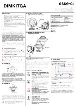
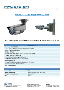
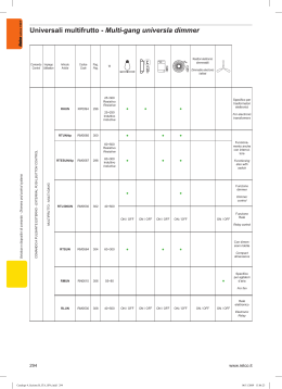
Art.SL5478 Handsfree Videomonitor - Art.SL5478 Videocitofono Vivavoce 34,50 164,00 B 11 12 13 14 15 16 17 18 19 20 1 2 3 4 5 6 7 8 9 10 130,00 A C 72 ON ON 12345678 1234 1 3 2 4 VIDEX ELECTRONICS S.p.A. VX2200 “2 WIRE” Bus Digital System ART.SL5478 VIDEOCITOFONO VIVAVOCE SLIM PER SISTEMI VIDEO CON/SENZA COASSIALE ART.SL5478 SLIMLINE HANDS FREE VIDEOMONITOR FOR COAX/NON COAX VIDEO SYSTEMS Descrizione Videocitofono vivavoce slim intelligente specifico per il sistema VX2200 con monitor a colori LCD TFT da 3,5”, pulsanti “apri-porta”, “risposta/autoaccensione”, “privacy on/off” e 3 pulsanti di servizio più 4 LED* relativi al funzionamento dei pulsanti sopra indicati. Regolazioni: volume altoparlante, volume del tono di chiamata, luminosità e saturazione. Numero di squilli, tipo suoneria, durata privacy e modo video programmabili. Nota elettronica offerta dal sistema più ingressi attivo bassi per chiamata locale ed allarme. Description Intelligent slimline Hands free video monitor for the VX2200 digital system incorporating a 3,5” full colour active matrix LCD monitor, with “door open” , “answer/camera recall”, “privacy on/off” buttons and 3 service buttons plus 4 LEDs related to the operation of the 4 buttons mentioned above. Controls: loudspeaker volume, call tone volume, brightness and hue. Programmable number of rings, privacy duration, door opening time and video mode. Electronic call tone offered by the system plus active low inputs for local bell and alarm. Pulsanti e Regolazioni Fino a quando resta premuto chiude il morsetto 12 (S1) verso massa (max 24Vdc 200mA). ) verso Fino a quando resta premuto chiude il morsetto 14 ( massa (max 24Vdc 50mA). Alla ricezione della chiamata, abilita l’inizio conversazione. Il relativo LED 2 si accende. Ad impianto spento, premere il pulsante tante volte quant’è il valore dell’identificativo del posto esterno da accendere. Il relativo LED 2 si accende. Ad impianto acceso, consente lo spegnimento manuale (rapida pressione del tasto). In ogni caso lo spegnimento è automatico (il LED 2 si spegne) allo scadere del tempo di conversazione. Premendo il pulsante per più di 2 secondi, il videocitofono passa nel modo trasmissione ad una via: per parlare con l’esterno occorre tenere premuto il pulsante (il LED 2 lampeggia rapidamente), mentre per ascoltare il visitatore occorre lasciare il pulsante (il LED 2 lampeggia lentamente). Trascorsi 10 secondi, senza premere nuovamente il pulsante, il sistema si spegne. Il videocitofono torna al funzionamento normale alla successiva accensione. Push buttons and Controls When pressed, shorts terminal 12 (S1) to ground (max 24Vdc 200mA). ) to ground (max 24Vdc When pressed, shorts terminal 14 ( 50mA). Pressing this button during an incoming call will open the speech in duplex mode allowing free speech with the caller in both directions (LED “2” next to this button will illuminate). When the system is in standby (No call on the system), this button will recall the picture and speech from one of the doors. Simply press the button as many times as the doors ID number (i.e. pressing the button twice will switch on the camera and speech to door ID 2 after a short delay). The LED 2 next to the button will Illuminate. During a call, pressing this button momentarily will end the call, LED 2 next to the but will switch off). The system will automatically switch off when the conversation time expires. Pressing and holding the button for more than 2 seconds will switch the videophone into SIMPLEX speech mode. Press and hold the button to speak to the caller (LED 2 will flash rapidly), release the button to listen (LED 2 will flash slowly). If the button is not pressed for 10 seconds the system will switch off. The videophone will revert to duplex speech when another call is made. Fino a quando resta premuto chiude il morsetto 13 (S2) verso massa (max 24Vdc 200mA). Attiva/Disattiva il servizio “privacy”. Con il servizio attivo il relativo LED 3 è accesso e le chiamate entranti vengono ignorate. A sistema acceso, apre la porta. L’apertura è indicata da un segnale acustico (se la fonia è attiva) per la durata del tempo d’apertura porta. Se il relativo filo è stato collegato, il LED 4 “door open” resterà acceso fino a quando la porta resta aperta. A sistema spento, effettua la chiamata al centralino di portineria se presente nell’impianto. When pressed, shorts terminal 13 (S2) to ground (max 24Vdc 200mA). Enables / Disables the privacy service. When privacy is enabled calls will not be received. LED 3 next to the button will illuminate when the privacy service is enabled. During a call, operation of this button will release the door from which the call is coming from. This will be confirmed by an acoustic signal (if the speech is enabled) for the duration of the “door open time”. If terminal 19 is connected, the “door open” LED 4 next to the button will also illuminate. When the video monitor is not engaged in a call, operation of this button will book a call from the concierge (If available). Regolazione Volume Altoparlante Regolazione Volume Tono di Chiamata Regolazione Luminosità Regolazione Colore Loudspeaker volume control Call tone volume control Brightness control Colour intensity control Programmazione La programmazione del videocitofono consiste nell’impostazione della modalità video (coassiale o segnale video bilanciato) e di alcuni parametri quali la durata della funzione privacy, il numero di squilli e il tipo di suoneria Programming Setup is carried out using the push buttons on the front of the unit and the dip-switches located on the rear of the unit. Adjustments include the selection of either coaxial or balanced video input, privacy time, the number of rings and the call tone melody. IMPOSTAZIONE MODALITA’ VIDEO La modalità video viene impostata tramite il Dip-Switch a 4 vie accessibile dalla parte posteriore del blocco superiore del videocitofono. Gli switch 3 e 4 servono ad adattare l’impedenza del segnale video; in caso di più videocitofoni collegati in parallelo, devono essere impostati entrambi ad OFF per tutti i videocitofoni ad eccezione dell’ultimo in ordine di collegamento. Modo Video Terminazione video 75 Ohm Switch 1,2 Modo Switch 3,4 Terminazione VIDEO MODE SETUP The video mode setup is carried out by the 4 way Dip-Switch accessible from the rear side of the videophone. Switches 1 and 2 adjust the video signal impedance. when using more than one videomonitor in parallel (without a video splitter) put both switches in the OFF position on all but the last videomonitor (end of line). Video Mode Switches 1,2 Mode 75 Ohm Video Termination Switches 3,4 Termination Coassiale Abilitata Coax Enabled Bilanciato Disabilitata Balanced Disabled 73 VX2200 “2 WIRE” Bus Digital System VIDEX ELECTRONICS S.p.A. PROGRAMMAZIONE Nr.SQUILLI, SUONERIA E DURATA PRIVACY I valori impostati di fabbrica sono: 6 squilli, suoneria 1 e durata privacy illimitata. NUMBER OF RINGS, MELODY AND PRIVACY DURATION PROGRAMMING The preset values are: 6 rings, melody 1 and no time out privacy duration. Per programmare il numero di squilli Premere e tenere premuto (10 secondi circa) il pulsante “ ” fino a quando il relativo LED si accende e l’unità emette un bip. Premere nuovamente il pulsante “ ” per un numero di volte pari al numero di squilli (max 9) da programmare Es. 5 volte per impostare 5 squilli. Selezionato il numeri di squilli desiderato, attendere circa 5 secondi senza compiere alcuna operazione: un bip e lo spegnimento del LED confermeranno l’avvenuta memorizzazione. Number of rings Press and hold (for approx 10 seconds) the “ ” button until the LED next to the button illuminates and the unit emits a beep. Press again the “ ” button as many times as the number of rings needed (i.e. 6 times = 6 rings, maximum 9 times). Once the value of rings has been reached, wait 5 seconds for a beep and the LED turning OFF. The new value is stored. Per programmare la suoneria Premere e tenere premuto (10 secondi circa) il pulsante “ ” fino a quando il relativo LED si accende e l’unità riproduce la suoneria correntemente programmata. Premere nuovamente il pulsante “ ” per ascoltare le suonerie disponibili (max 9). Selezionata la suoneria desiderata, attendere circa 5 secondi senza compiere alcuna operazione: un bip e lo spegnimento del LED confermeranno l’avvenuta memorizzazione. Melodies Press and hold (for approx 10 seconds) the “ ” button until the LED next to the button illuminates and the unit plays the current programmed melody. Press again the “ ” button to listen to the available melodies (maximum 9). Once the chosed melody has been reached, wait 5 seconds for a beep and the LED turning OFF. The new melody will be stored Per programmare la durata della funzione “privacy” Premere e tenere premuto (10 secondi circa) il pulsante “ ” fino a quando il relativo LED si accende e l’unità emette un bip. Ogni pressione del tasto “ ” incrementa (partendo da 0) la durata del servizio privacy di 1/4 d’ora: premere un numero di volte pari alla durata desiderata (max 80 volte = 20 ore). Impostata la durata desiderata, attendere circa 5 secondi senza compiere alcuna operazione: un beep e lo spegnimento del LED confermeranno l’avvenuta memorizzazione. Per impostare la durata illimitata (servizio attivato e disattivato tramite il pulsante“ ”), attendere che avvenga la memorizzazione senza premere nulla. Privacy duration time Press and hold (for approx 10 seconds) the “ ” button until the LED next to the button illuminates and the unit beeps. Each time the “ ” button is pressed, it will increase (starting from 0) the privacy duration by 15 minutes, press until the required duration has been reached, when reached, wait 5 seconds for a beep and the LED turning OFF. The new time will be stored. To set the privacy with no time out (privacy enabled or disabled by pressing the “ ” button), don't press any buttons once in privacy programming mode and wait 5 seconds for the beep and LED to go off. Impostazione indirizzo videocitofono L’indirizzo del videocitofono è codificato in binario tramite il dip-switch ad 8 vie situato al suo interno. Ogni switch corrisponde ad un bit che può essere a 0 (OFF) o 1 (ON), a ciascun bit corrisponde un peso decimale in base alla posizione: per impostare l’indirizzo desiderato, mettere ad ON (1) gli switch la cui somma dei pesi corrisponde al valore dell’indirizzo. Ad esempio, per impostare l’indirizzo 37, mettere ad ON gli switch 1, 3 e 6 (1+4+32=37). Videomonitor address setup Each videomonitor must be address in binary (PHONE ID) using the 8 way dipswitches located on the rear of the unit. Each switch correspond to one bit which can have a value 0 (OFF) or 1 (ON). Each bit corresponds to a decimal weight depending on the position: Switch 1 = decimal 1, 2=2, 3=4, 4=8, 5=16, 6=32, 7=64, 8=128. I.E. to set the address 37, put switches 1, 3 and 6 on (1+4+32=37). Addr. Decimal Weight – Peso Decimale Indir. Switches – Switch 8 7 6 5 4 3 2 1 128 64 32 16 8 4 2 1 OFF OFF OFF OFF OFF OFF OFF ON 0 0 0 0 0 0 0 1 OFF OFF OFF OFF OFF OFF ON OFF 0 0 0 0 0 0 1 0 2 OFF OFF OFF OFF OFF OFF ON ON 0 0 0 0 0 0 1 1 3 OFF OFF OFF OFF OFF ON OFF OFF 0 0 0 0 0 1 0 0 4 OFF OFF ON OFF OFF ON OFF ON 0 0 1 0 0 1 0 1 37 ON OFF ON ON OFF ON OFF OFF 1 0 1 1 0 1 0 0 180 Specifiche tecniche Tensioni d’alimentazione Assorbimenti Temperatura di Lavoro 74 : : : : : 17÷20Vdc 12÷14Vdc 12mA in stand-by (on 12Vdc) 70mA Max (on 12Vdc) 250mA Max (on 20Vdc) -10ºC +50ºC Technical specification Working Voltage : Power Consumption : Working Temperature: 17÷20Vdc 12÷14Vdc 12mA in stand-by (on 12Vdc) 70mA Max (on 12Vdc) 250mA Max (on 20Vdc) -10ºC +50ºC 1 VIDEX ELECTRONICS S.p.A. VX2200 “2 WIRE” Bus Digital System Art.SL5478 - SEGNALI SCHEDA DI CONNESSIONE Art.SL5478 - PCB CONNECTION BOARD SIGNALS Morsetto Terminal Descrizione Description Ingresso alimentazione video 17÷20Vdc +20V 1 Video power supply 17÷20Vdc Ingresso alimentazione video 17÷20Vdc +20V 2 Video power supply 17÷20Vdc Alimentazione video riferimento di massa GND 3 Video power supply ground reference Alimentazione video riferimento di massa GND 4 Video power supply ground reference Sincronia V2 segnale video bilanciato (modo seg. video bil.) Segnale video composito (modo segnale video coassiale) V2/V 5 Balanced video signal V2 sync.(balanced video signal mode) Composite video signal (coax video signal mode) Sincronia V1 segnale video bilanciato (modo seg. video bil.) V1 6 Balanced video signal V1 sync.(balanced video signal mode) Linea BUS L 7 BUS line GND 8 BUS line ground reference Ingresso chiamata locale (attivo basso) LB 9 Local bell input (active low) Ingresso segnale d’allarme (attivo basso) AL 10 Alarm input (active low) GND 11 Ground Pulsante S1 (chiusura verso massa quando premuto) S1 12 S1 Push button (close to ground when pressed) Pulsante S2 (chiusura verso massa quando premuto) S2 13 S2 Push button (close to ground when pressed) Linea BUS riferimento di massa Massa Pulsante (chiusura verso massa quando premuto) 14 Push button (close to ground when pressed) Uscita +12Vdc per alimentazione distr. video Art.894 +VD 15 +12Vdc output to supply the video distributor Art.894 Massa GND 16 Ground Uscita stabilizzata +12Vdc 12VO 17 Stabilized +12Vdc output Ingresso alimentazione +12Vdc 12VI 18 +12Vdc Power supply input Ingresso di alimentazione per accensione LED ausiliario “1” LDA 19 Auxiliary LED “1” power supply input Massa GND 20 Ground 75 VX2200 “2 WIRE” Bus Digital System VIDEX ELECTRONICS S.p.A. Art.SL5478 Istruzioni di fissaggio a parete Art.SL5478 Wall mounting instructions J B B H C 135cm C A Fig.1 Fig.2 F E A D D G A Fig.3 Per installare il videocitofono Art.SL5478 è necessario aprirlo: facendo riferimento alla figura 4, svitare la vite “G”, tirare a se il coperchio “D” quindi spingerlo verso l’alto (o in avanti se si effettua l’operazione tenendo il videocitofono in orizzontale) e scollegare il connettore maschio “E” (Fig.3) dal connettore femmina “F” (Fig.3) della scheda di connessione alloggiata sulla base “A”. Appoggiare a parete la base “A” ad una altezza di circa 135cm (Fig.1) dal pavimento finito e prendere i riferimenti per i fori di fissaggio, tenendo presente che i conduttori devono passare attraverso la fessura “H” (Fig.2). Realizzare i fori e fissare a parete la base “A” con l’ausilio dei 2 tasselli ad espansione “B” e delle due viti “C” come mostrato in figura 2. Effettuare le connessioni come da schema fornito a corredo. Come mostrato in figura 3, avvicinare il coperchio “D” alla base “A”, inserire il connettore “E” nel connettore “F” (sostenere con le mani il peso del coperchio) e proseguire con il passo successivo. Con l’ausilio degli incastri “J” (Fig.2) agganciare il coperchio “D” alla base “A” come mostrato in figura 4 quindi spingere la parte inferiore del coperchio “D” verso la base “A” e procedere al collaudo del sistema. Terminato il collaudo del sistema, assicurare il coperchio “D” alla base “A” con l’ausilio della vite “G” (Fig.4). 76 Fig.4 To install Art.SL5478 it is necessary to open it. Follow picture n.4: turn screw “G”, pull cover “D” and lift it up (or push it forward if the videomonitor is in horizontal position), then disconnect plug “E” (Fig.3) from plug “F” on the connection board housed on the bottom “A”. Put the bottom “A” against the wall at 135cm from the finished floor (Fig.1). All cables must be fed through hole “H” (Fig.2). Leaving approximately 135cm from the finished floor, fit the bottom “A” against the wall and mark the fixing holes considering that the cables must fed through the opening “H” (Fig.2) Make the holes, and fix bottom “A” on the wall using the two wall plugs “B” and the two screws “C” as shown in figure 2. Make all connections as per provided diagram. As shown in figure 3, move cover “D” close to bottom “A”, connect plug “E” to plug “F” on the connection board then proceed with the next step. Hook cover “D” to bottom “A” by using the two clips “J” (Fig.2) as shown in figure 4 then push down cover “D” towards bottom “A”. Then proceed with system testing. When finished the testing, fix cover “D” at the bottom “A” using the screw “G” (Fig.4).
Scarica