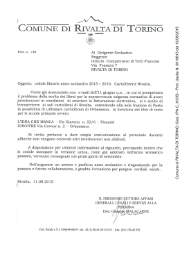
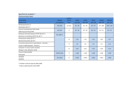
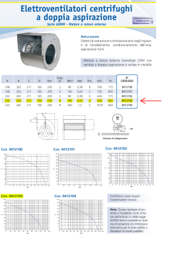
1. GENERAL CHARACTERISTICS
x1R Easy
The I/O logic (code 587.00.0698.0007 – fig 1) is a module that, when connected to the x1R easy lock via a
two-way 3 conductor (Tx, Rx and GND) communication interface, extends its potential, making it possible to:
acquire “Open” and “Close” commands via 2 remote digital inputs;
control 4 relay outputs
1
TECHNICAL SPECIFICATIONS
2
WARNINGS
3
INSTALLATION EXAMPLES
4
ELECTRICAL CONNECTIONS
5
Overall dimensions 106x100x58 mm.
Maximum relay switching current: 1A
Power supply 9/24 VDC
Maximum relay switching power: 60VA/24W
Absorption 100 mA
2 optoinsulated digital inputs (9-24 VAC/DC)
for the “Open” and “Close” commands.
1 Relay for bolt retracted (in) position
1 POWER ON indication LED.
1 door position Relay
1 indication LED for each active relay.
1 Relay for latch extracted (out) position
1 indication LED for each active digital
input.
1 Relay for the motorised door opener
control (Relay activated for 1 sec.).
1 hook for fixing the DIN bar.
Maximum
relay
120VAC/60VDC
1 two-way 3 conductor (Tx, Rx, GND)
communication channel.
voltage:
4. INSTALLATION EXAMPLES
105 mm.
When using the I/0 logic with an x1R Easy lock, before proceeding with
the connection make sure that the black condenser is NOT between the
black and brown wires in the communication cable. If it is remove it by
cutting the terminals. The presence of the condenser (filter) between the
black and brown cables prevents communication between the x1R Easy
lock and the I/0 logic.
4.1 INSTALLATION EXAMPLES
Installation with Fiam 9VDC – 3 A feeder
Installation with 9/24 VDC – 3A feeder and rechargeable
battery kit / Fiam battery charger
1. Door contact supplied with lock
2
1. Door contact supplied with lock
2
2. Internal facing plate (cod. 98PI0698)
2. Internal facing plate (cod. 98PI0698)
3. Cable gland (cod. 8810.00000 - for openings up to 90°)
(cod. 6013.0000 - for openings up to 180°)
x1R Easy
1
7
Side
view
3. WARNINGS
2. TECHNICAL SPECIFICATIONS
switching
Top
View
58 mm.
GENERAL CHARACTERISTICS
100 mm.
INDEX
3
1
4. Communication cable supplied with lock
(3 poles: black, brown, blue)
4
3. Cable gland (cod. 8810.00000 - for openings up to 90°)
(cod. 6013.0000 - for openings up to 180°)
x1R Easy
3
4
5. I/O Logic (cod. 587.00.0698.007)
5. I/O Logic (cod. 587.00.0698.007)
5
6
4. Communication cable supplied with lock
(3 poles: black, brown, blue)
6. Fiam 9VDC/2,89A feeder (cod. 587.00.0000.3809)
7. Power supply cable supplied with lock
(2 poles: red, black)
5
8
9
7
9/24 VDC
11
10
7. Power supply cable x1R Easy supplied with lock
(2 poles: red, black)
8. Fiam battery charger (cod. 582.00.6001.0016)
9. Fiam 230/12 VAC transformer (cod. 582.00.0698.0000)
10. Fiam battery holder (cod. 587.00.0698.0000)
230 VAC
230 VAC
6. Set of rechargeable Fiam batteries (cod. 582.00.6000.0016)
11. External 9/24 VDC 2A power supply (not supplied).
6
5. ELECTRICAL CONNECTIONS
9/24
VAC/VDC
9/24
VAC/VDC
6
7
8
9
Note: each digital inputs
has a statud LED.
J1
P2
(”CLOSE” button
not supplied)
LED Power “ON”
J2
The 3 poles communication cable
supplied with the lock (n° 4
paragraph 4) is 4 meters long; if
you need to extend the cable, the
maximum length is 15 meters,
using an AWG25 cable.
Before switching on the
power to the I/O Logic
and the x1R Easy lock
connect the communication
cable.
Communication cable
with 3 poles: black,
brown and blue supplied
with the x1R Easy lock.
EARTH
1
2
3
4
5
NEGATIVE FEED
9/24 VDC
BLACK WIRE
POSITIVE FEED
9/24 VDC
Note:
each relay has a status LED.
®
BROWN WIRE
BLUE WIRE
w w w. i s e o. c o m
J3
Note: the bridges (JP1, JP2,
JP3, JP4) can be used to
configure the respectives
relay to be NO (factory
setting) or NC (by moving
the bridge to the 1-2
position.
x1R Easy
10
11
12
13
14
15
16
17
C
NO
C
NO
C
NO
C
NO
RL1
RL1
RL2
RL2
RL3
RL3
RL4
RL4
Motorised latch bolt
position relay
Bolt retracted
position relay
Door position relay
Relay (1 sec. impulse)
controlling motorised
“door opened”
ELECTRONIC SUPPORT SERVICE
www.iseozero1.com
Non contractual document. Subject to change.
Documento non contrattuale. Con riserva di modifica.
Codice: 6000006980007 Installation Manuale I/O LOGIC.
(Eng/It) Rev. 002 data 14/11/2013
P1
(”OPEN” button
not supplied)
1. CARATTERISTICHE GENERALI
x1R Easy
La logica I/O (cod. 587.00.0698.0007) è un modulo che connesso alla serratura x1R Easy attraverso
un’interfaccia di comunicazione bidirezionale a 3 conduttori (Tx, Rx, GND), ne arricchisce le potenzialità con la
possibilità di: acquisire i comandi “Apri” e “Chiudi” tramite 2 ingressi digitali remoti;
comandare 4 uscite a relè
1
SPECIFICHE TECNICHE
2
AVVERTENZE
3
ESEMPI DI INSTALLAZIONE
4
COLLEGAMENTI ELETTRICI
5
Vista
superiore
58 mm.
CARATTERISTICHE GENERALI
100 mm.
INDICE
105 mm.
3. AVVERTENZE
2. SPECIFICHE TECNICHE
Dimensioni di ingombro 105x100x58 mm.
Corrente massima di commutazione Relè: 1A
Alimentazione 9/24 VDC
Potenza massima commutabile Relè: 60VA/24W
Assorbimento 100 mA
2 Inputs digitali optoisolati (9÷24 VAC/DC)
per i comandi “Apri” e “Chiudi”
1 Relè posizione catenacci arretrati (dentro)
1 LED di segnalazione POWER ON
1 Relè posizione anta
1 LED di segnalazione per ogni Relè attivo
1 Relè posizione scrocco estratto (fuori)
1 LED di segnalazione per ogni ingresso
digitale attivo
1 Relè di comando apriporta motorizzato
(Relè eccitato per 1 sec.)
1 Gancio per fissaggio su barra DIN
Tensione massima di commutazione Relè:
120VAC/60VDC
1 Canale di comunicazione bidirezionale a
3 conduttori (Tx, Rx, GND)
4. ESEMPIO DI INSTALLAZIONE
In caso di utilizzo della Logica I/O con la serratura x1R Easy, prima di
procedere con il collegamento, verificare che tra i fili nero e marrone del
cavo di comunicazione NON sia presente il condensatore nero: nel caso
sia presente eliminarlo tagliandone i terminali.
La presenza del condensatore (filtro) tra i fili nero e marrone inpedisce la
comunicazione tra la serratura x1R Easy e la Logica I/O.
4.1 ESEMPIO DI INSTALLAZIONE
Installazione con alimentatore Fiam 9VDC - 3A
Installazione con alimentatore 9/24 VDC - 3A e kit batterie
ricaricabili/carica batterie Fiam
1. Contatto porta in dotazione con la serratura
2
1. Contatto porta in dotazione con la serratura
2
2. Mostrina interna (cod. 98PI0698)
2. Mostrina interna (cod. 98PI0698)
3. Passacavo (cod. 8810.00000 - per aperture fino a 90°)
(cod. 6013.0000 - per aperture fino a 180°)
x1R Easy
1
Vista
laterale
7
3
1
4. Cavo di comunicazione in dotazione con la serratura
(3 poli: nero, marrone, blu)
4
3. Passacavo (cod. 8810.00000 - per aperture fino a 90°)
(cod. 6013.0000 - per aperture fino a 180°)
x1R Easy
3
4
5. Logica I/O (cod. 587.00.0698.007)
5. Logica I/O (cod. 587.00.0698.007)
5
6
6. Alimentatore Fiam 9VDC/2.89A (cod. 587.00.0000.3809)
7. Cavo alimentazione in dotazione con la serratura
(2 poli: rosso, nero)
4. Cavo di comunicazione in dotazione con la serratura
(3 poli: nero, marrone, blu)
5
8
9
7
9/24 VDC
11
10
7. Cavo alimentazione in dotazione con la serratura
(2 poli: rosso, nero)
8. Caricabatterie Fiam (cod. 582.00.6001.0016)
9. Trasformatore Fiam 230/12 VAC (cod. 582.00.0698.0000)
10. Portabatterie Fiam (cod. 587.00.0698.0000)
230 VAC
230 VAC
6. Set batterie ricaricabili Fiam (cod. 582.00.6000.0016)
11. Alimentazione esterna 9/24 VDC 2A (non in dotazione)
6
5. COLLEGAMENTI ELETTRICI
P1
(pulsante “APRE”
non in dotazione)
9/24
VAC/VDC
6
7
8
9
J1
P2
(pulsante “CHIUDE”
non in dotazione)
LED Power “ON”
J2
Il cavo di comunicazione a 3 poli
in dotazione con la serratura (n°
4 paragrafo 4) è lungo 4 metri; nel
caso fosse necessario allungare
questo cavo, la lunghezza
massima è di 15 metri, utilizzando
un cavo AWG25.
Cavo comunicazione
di 3 poli, nero, marrone,
blu in dotazione con la
serratura x1R Easy
Nota: ogni ingresso digitale
dispone di un LED di stato.
MASSA
1
2
3
4
5
NEGATIVO ALIMENTAZIONE
9/24 VDC
FILO NERO
POSITIVO ALIMENTAZIONE
9/24 VDC
FILO BLU
w w w. i s e o. c o m
J3
Nota: i ponticelli (JP1, JP2,
JP3, JP4) permettono di
configurare il rispettivo relè
in versione NO (impostazioni
di fabbrica) o in versione NC
(spostando il ponticello in
posizione 1-2).
Nota: ogni relè dispone di
un LED di stato.
®
FILO MARRONE
10
11
12
13
14
15
16
17
C
NO
C
NO
C
NO
C
NO
RL1
RL1
RL2
RL2
RL3
RL3
RL4
RL4
Relè posizione
scrocco motorizzato
Relè posizione
catenacci arretrati
Relè posizione
anta
Relè (impulso di 1 sec.)
comando “apriporta”
motorizzato
ELECTRONIC SUPPORT SERVICE
www.iseozero1.com
Non contractual document. Subject to change.
Documento non contrattuale. Con riserva di modifica.
Codice: 6000006980007 Installation Manuale I/O LOGIC.
(Eng/It) Rev. 002 data 14/11/2013
9/24
VAC/VDC
x1R Easy
Prima di alimentare la
Logica I/O e la serratura
x1R Easy collegare il
cavo di comunicazione.
Scarica