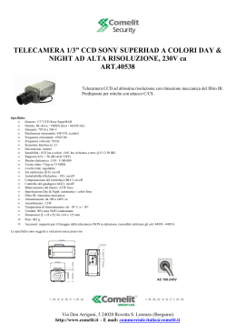
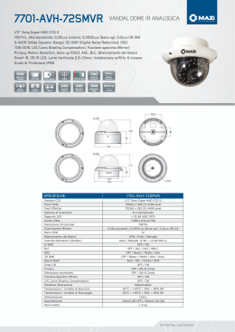
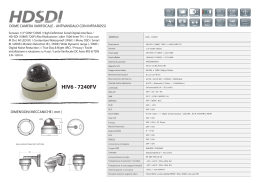
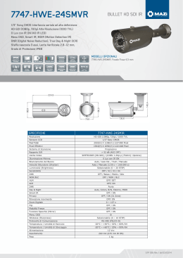
Via Dimo Vioni ,5 - Fraz. S. Rocco 42016 Guastalla (RE) - ITALY Tel:0522-832004 Fax:0522-832012 E-mail: [email protected] - Website: www.tecnoelettra.it TECNOELETTRA srl TE804 TE804 Controllo gruppi elettrogeni con controllo automatico della rete Gen-set control with Automatic Mains Failure MANUALE OPERATIVO INSTRUCTIONS MANUAL ATTENZIONE!! Questi apparecchi devono essere installati da personale qualificato, nel rispetto delle vigenti normative impiantistiche, allo scopo di evitare danni a persone o cose. I prodotti descritti in questo documento sono suscettibili in qualsiasi momento di evoluzioni o di modifiche. Le descrizioni ed i dati a catalogo non possono pertanto avere alcun valore contrattuale WARNING! This equipment is to be installed by qualified personnel, complying to current standards, to avoid damages or safety hazards. Products illustrated herein are subject to alteration and changes without prior notice. Technical data and descriptions in the documentation are accurate, to the best of our knowledge, but no liabilities for errors, omissions or contingencies arising therefrom are accepted. Introduzione Questo apparecchio è stato studiato per facilitare l’utilizzo sia dell’installatore che dell’operatore del gruppo elettrogeno, evitando quindi di ricorrere alla continua e tediosa consultazione del manuale operativo. Nelle varie situazioni di utilizzo, quali: impostazione parametri di set-up, visualizzazione dati, condizioni di allarme, ecc., un Led sul tasto HELP si accende per segnalare la disponibilità di un messaggio di aiuto. Questo manuale quindi contiene le sole informazioni indispensabili per iniziare l’operatore all’utilizzo dell’apparecchio e tabelle relative ad allarmi, parametri, funzioni programmabili e caratteristiche tecniche. Introduction This device has been designed to facilitate the use by the gen-set operator, by avoiding the continuous need to consult the instructions manual. In most utilisation circumstances, for instance parameter setting, data display, alarm conditions, etc., the LED on the HELP key is switched on when a help message is available for consulting. Therefore, this manual contains essential information, such as details for the operator for the TE804 use, alarms table, parameters tables, functions list and technical characteristics. Tastiera Tasto di HELP - ll Led acceso indica la disponibilità di un messaggio di aiuto. Premendo il tasto si ha la visualizzazione del testo di help, relativo all’operazione che si sta effettuando. Tasti ENTER e EXIT - Tasto ENTER per confermare comandi od operazione o per entrare in un menù. Tasto EXIT per rifiutare un’operazione, per uscire dai menù o per uscire dal messaggio di help. Tasti freccia “” e “” - Servono per muoversi tra le pagine di visualizzazione dati o per scegliere i parametri nei menù. Tasti di “–“ e “+” – Servono per visualizzare dati alternativi alla pagina dati selezionata e per modificare i parametri. Tasti OFF/RESET, MAN, AUT e TEST - Servono per la scelta della modalità di funzionamento. Il Led acceso indica la modalità scelta, se è lampeggiante significa che il controllo remoto è attivo. Tasti START e STOP - Funzionano solo in modo MAN e servono per avviare e fermare il gruppo elettrogeno. Premendo brevemente il tasto START si ha un tentativo di avviamento, tenendolo premuto si può prolungare la durata dell’avviamento. Il Led lampeggiante sul simbolo motore indica motore in moto con allarmi inibiti, acceso normalmente al termine del tempo di inibizione allarmi. Il motore può essere fermato anche mediante il tasto OFF/RESET. TE804 Tasti MAINS e GEN – Funzionano solo in modo MAN e servono per commutare il carico dalla rete al generatore e viceversa. I Led accesi in prossimità dei simboli della rete e generatore indicano le rispettive tensioni disponibili entro i limiti predefiniti. I Led accesi in prossimità dei simboli di commutazione indicano l’avvenuta chiusura dei dispositivi di commutazione, lampeggianti se il segnale di ritorno (feed-back) di effettiva chiusura o apertura dei dispositivi di commutazione sono errati. Keyboard HELP key – The illuminated LED means a help message is available. By pressing the key, a help message concerning the current operation is displayed. ENTER and EXIT keys - Press ENTER to confirm operations or to enter the menu. Press EXIT to refuse an operation or to exit a menu and help message. “” and “” arrow keys – Press these keys to shift to the different pages of data display or to select parameters. “–“ and “+” keys Press these keys to display other data of the selected data page or to modify the parameters. OFF/RESET, MAN, AUT and TEST keys – Press these keys to select the operating mode. The illuminated LED indicates the selected operating mode; if it is flashing, remote control is active. START and STOP keys – These work in MAN operating mode only, used to start and stop the engine. By quickly pressing the START key, one start attempt takes place; by keeping the START key pressed, the duration of the start attempts can be extended. The flashing LED of the engine symbol denotes engine started, with alarms inhibited; and is constantly on at the end of the alarms inhibition time. The engine can be stopped using the OFF/RESET key. TE804 MAINS and GEN keys – They work in MAN operating mode only, used to switch the load from mains to generator and vice versa. The illuminated LEDs of the mains and generator symbols indicate the respective voltages are within preset limits. The illuminated LEDs of the changeover symbols indicate the actual closing of switching devices; when flashing, there is an incorrect feedback signal for the actual closing or opening of the switching devices. Scroll rapido – E’ possibile scorrere le videate e i parametri in modo rapido, tenendo premuto il tasto freccia “” o “”. Quick Scroll – The screens and parameters can be scrolled by keeping the key “” and “” pressed. Doc: MT2550013 rev01 (it-gb).doc 05/03/2007 p. 1 / 17 Via Dimo Vioni ,5 - Fraz. S. Rocco 42016 Guastalla (RE) - ITALY Tel:0522-832004 Fax:0522-832012 E-mail: [email protected] - Website: www.tecnoelettra.it TECNOELETTRA srl Display LCD Il display visualizza sia in forma grafica che alfanumerica dati ed informazioni. Premere i tasti freccia “” e “” per vedere le pagine di visualizzazione dei dati. Premere i tasti “–“ e “+” per vedere altri dati relativi alla stessa pagina di visualizzazione. L’apparecchio è impostato di default per ritornare alla pagina principale dopo un tempo di 60s dall’ultimo tasto premuto. LCD screen The LCD shows data and information in graphic and alphanumeric forms. Press the “” or “” keys to view the data pages. Press the “–“ or “+” keys to see alternative data on the same page. The TE804 is set to return to the main page 60 seconds after the last key is pressed. Modo di funzionamento TE804 Modo OFF/RESET- Il motore non può funzionare. Se la rete è presente viene allacciata al carico. Passando a questa modo di funzionamento, il motore se in funzione si ferma immediatamente ed eventuali allarmi vengono resettati. L’allarme non si resetta se permane la causa che lo ha provocato. Modo MAN - Il motore può essere avviato e fermato solo manualmente agendo sui tasti di START e STOP, cosi pure la commutazione del carico dalla rete al generatore mediante i tasti MAINS e GEN e viceversa. Sempre in modo MAN: al comando di start tenendo premuto il pulsante si ha il prolungamento del tempo di avviamento impostato, al comando di stop tenendo premuto il pulsante per un tempo superiore a 6 secondi si ha l’attivazione (spurgo) dell’elettrovalvola carburante per 4 minuti. Modo AUT - Il motore parte automaticamente in caso di assenza rete (fuori dai limiti impostati) e si ferma in presenza della stessa. Modo TEST – Il motore parte immediatamente anche in presenza di rete, in mancanza della rete il carico commuta sul generatore. Passando nuovamente in modo AUT il motore si ferma, ovviamente se la rete è presente. Operating mode TE804 OFF/RESET mode – The engine cannot operate. If the mains is present, the load is switched to the mains. Changing from TEST, AUT or MAN to the OFF/RESET mode and if the engine is running, the engine is immediately stopped and eventual alarms are reset. If the cause of the alarm is still present, it cannot be reset. MAN mode – The engine can be manually started or stopped using the START and STOP keys only, in addition to load switching from mains to generator and vice versa, by means of the MAINS and GEN keys. Always in MAN mode, at the start command and by keeping the key pressed, the preset starting time can be prolonged while at the stop command and by keeping the key pressed for more than 6 seconds, the fuel valve is discharged for 4 minutes. AUT mode – In case of mains not present (out of the preset limits), the engine automatically starts or stops when the mains returns. TEST mode – The engine immediately starts even if the mains is present. In case the mains is not present, the load is switched to the generator. Changing to the AUT mode and if the mains is present, the engine will stop. Allarmi Al sorgere di un allarme, la parte inferiore del display viene occupata per la visualizzazione dello stesso. Nel caso di più allarmi questi vengono visualizzati singolarmente in sequenza. Per ogni allarme è disponibile un messaggio di aiuto per individuare la possibile origine del problema. Il reset degli allarmi può essere così effettuato: - premendo il tasto OFF/RESET l’allarme viene azzerato impedendo l’involontario avviamento del gruppo elettrogeno. - mantenendo premuto il tasto EXIT e quindi premendo il tasto OFF/RESET l’allarme viene azzerato senza modificare la modalità di funzionamento. Se l’allarme non si resetta, significa che non è stata rimossa la causa che lo ha provocato. Durante le operazioni di visualizzazione degli eventi (event-log) e quelle di set-up nessun allarme viene visualizzato. Alarms When an alarm arises, the lower section of the display is used to view it. In case of two or more alarms, they are individually shown in sequence. A help message is available for every alarm, in order to locate the possible alarm source. Alarm conditions can be cleared and the unit reset as indicated below: - By pushing the OFF/RESET key, the alarm is cleared and any unintentional engine starting is prevented. - By keeping the EXIT key pressed and then pushing the OFF/RESET key, the alarm is cleared but the operating mode is maintained. If the alarm does not clear, this means the alarm conditions are still present. During event-log sessions and set-up operations, no alarms are viewed. ATTENZIONE! Se l’apparecchio sta funzionando in modalità AUT o TEST , il reset degli allarmi mediante i tasti EXIT + OFF/RESET può causare l’avviamento automatico del gruppo. CAUTION! If the unit is operating in AUT or TEST mode, the alarm clearing via EXIT and OFF/RESET keys can cause the engine to automatically start. Messa in tensione Alla messa in tensione la TE804 si pone automaticamente in modo OFF/RESET. Se si necessita che mantenga lo stesso modo di funzionamento precedente lo spegnimento, si deve modificare un parametro del menù GENERALE. La TE804 può essere alimentato indifferentemente sia a 12 che a 24VDC, ma necessita della corretta impostazione della tensione di batteria nel menù BATTERIA, diversamente si avrà un’allarme relativo alla tensione di batteria. È indispensabile impostare i parametri del menù GENERALE (rapporto TA, tipo di connessione, tensione nominale, frequenza di sistema) e dei menù AVVIAMENTO MOTORE e CONTROLLO MOTORE, relativi al tipo di motore utilizzato. Power-up At power-up, the TE804 automatically sets to OFF/RESET mode. If one needs the TE804 set to the same mode before it was powered down, a parameter in the GENERAL menu must be modified. The TE804 can be supplied indifferently at 12 or 24VDC, but the exact battery voltage must be programmed in the BATTERY menu, otherwise a battery alarm will arise. It is also essential to set the parameters of the GENERAL menu (CT ratio, wiring configuration, rated voltage and frequency) as well as the ENGINE STARTING, ENGINE CONTROL menus, related to the type of engine used. Doc: MT2550013 rev01 (it-gb).doc 05/03/2007 p. 2 / 17 Via Dimo Vioni ,5 - Fraz. S. Rocco 42016 Guastalla (RE) - ITALY Tel:0522-832004 Fax:0522-832012 E-mail: [email protected] - Website: www.tecnoelettra.it TECNOELETTRA srl Set-up mediante tastiera Ci sono tre diversi menù per accedere ai parametri d’impostazione ed ai dati. Menù esteso: Accesso a tutti i parametri d’impostazione. Per entrare nel menù mantenere premuto il tasto OFF/RESET, quindi premere in sequenza due volte il tasto “-“, tre volte il tasto “+” e quattro volte il tasto “”, infine rilasciare il tasto OFF/RESET. Menù utente: Accesso ai parametri d’impostazione, limitato a quelli d’interesse dell’utilizzatore finale. Per entrare nel menù premere il tasto OFF/RESET per 5s, dopodiché rilasciarlo. Menù comandi: Accesso ai comandi di azzeramento dati, copia dei parametri e loro ripristino. Per entrare nel menù premere i tasti OFF/RESET e successivamente ENTER per 5s, dopodiché rilasciarli entrambi. Premere il tasto EXIT per uscire dal menù. Set-up via keyboard There are three different menus in order to have access to the parameters setting and relative data. Advanced menu: Access to all parameters setting. To enter the menu, keep the OFF/RESET key pressed, then push, in the following sequence, “-“ key twice, “+” key three times and “” key four times then finally release the OFF/RESET key. User’s menu: Access to parameters setting limited to those the final user needs. To enter the menu, press the OFF/RESET key for 5 seconds then release it. Commands menu: Access to data resetting, parameter copy and their restore. To enter the menu, press the OFF/RESET key, subsequently the ENTER key for 5 seconds and then release both of them. Press the EXIT key to exit the menu. Muoversi dentro il menu: Dopo essere entrati nel menù, premere i tasti freccia “” e “” per scegliere uno dei sotto menù d’impostazione (o un comando in caso di “Menù comandi”). Premere il tasto ENTER per accedere all’impostazione dei parametri (o per effettuare un comando). Premere i tasti freccia “” e “” per scegliere uno dei parametri, premere i tasti “–“ e “+” per modificalo. Premere il tasto EXIT per uscire dal sotto menù, premere nuovamente il tasto EXIT per uscire dal set-up. Copia di sicurezza dei dati: Per i soli dati di set-up modificabili da tastiera, è possibile fare una copia di sicurezza nella memoria flash della TE804. Questi stessi dati all’occorrenza possono essere ripristinati nella memoria di lavoro della TE804. I comandi di copia di sicurezza e ripristino dei dati sono disponibili nel menù comandi. Moving within the menu: After entering the menu, press the “” or “” key to select a sub-menu (or a command in the case of “Commands menu”). Press the ENTER key to access parameter setting (or to perform the command). Press “” or “” keys to select the parameter and press “–“ or “+” to modify it. Press the EXIT key to close the sub-menu and push it again to close the set-up. Data safety copy: A safety copy of the adjustable keyboard set-up data only can be made in TE804 flash memory. This same data can be restored, whenever required, to TE804 work memory. The commands and data restore of the safety copy are available in the commands menu. Set-up mediante PC Il set-up si effettua più agevolmente mediante PC connesso alla RS232 della TE804. Mediante il software di set-up è possibile effettuare il trasferimento dei parametri di set-up (precedentemente impostati) da TE804 a PC e viceversa. Il trasferimento dei parametri da PC a TE804 può essere parziale, cioè solo i parametri dei menù specificati. Oltre ai parametri con il PC è possibile definire: Testi di Help degli allarmi, nonché descrizione e testo di Help degli allarmi utente (User Alarms). Dati relativi alle caratteristiche delle curve dei sensori di pressione, temperatura, livello carburante e della protezione termica del generatore. Logo personalizzato che appare alla messa in tensione ed ogniqualvolta si esce dal set-up da tastiera. Pagina informativa dove poter inserire informazioni, caratteristiche, dati ecc. concernenti l’applicazione. Set-up by means of Personal Computer (PC) The set-up can be more easily done via PC connected to the TE804 RS232 port. Using the set-up software, it is possible to transfer parameters (previously set) from the TE804 to the PC and vice versa. The parameters transfer from the PC to the TE804 can be partial, that is specified parameters of the menus. In addition to the parameters setting with the PC, one can also define: Help text of the alarms, descriptions and help text of the User Alarms. All the data related to the curve characteristic of the pressure, temperature and fuel level sensors along with generator thermal protection. Custom logo, that appears on the display at power-up and at set-up exit via keypad. Information page, where one can write information, data, characteristics, etc., concerning a certain application. Doc: MT2550013 rev01 (it-gb).doc 05/03/2007 p. 3 / 17 Via Dimo Vioni ,5 - Fraz. S. Rocco 42016 Guastalla (RE) - ITALY Tel:0522-832004 Fax:0522-832012 E-mail: [email protected] - Website: www.tecnoelettra.it TECNOELETTRA srl Raccomandazioni Copia di sicurezza dei dati di set-up: Dato l’elevato numero di parametri della TE804, si raccomanda vivamente di effettuare il salvataggio dei dati di set-up sia su hard disk del PC che su floppy disk, ogniqualvolta che questi vengono modificati direttamente dalla tastiera dell’apparecchio. Rammentiamo che, per i soli dati di set-up modificabili da tastiera, è possibile fare una copia di sicurezza nella memoria flash della TE804. Questi stessi dati all’occorrenza possono essere ripristinati nella memoria di lavoro della TE804. I comandi di copia di sicurezza e ripristino dei dati sono disponibili nel menù comandi. Pagina informativa: La TE804 oltre alle pagine video per la visualizzazione di misure, dati, allarmi ecc. dispone di una pagina informativa di 8 righe per 32 caratteri a completa disposizione dell’utente. In questa pagina possono essere poste informazioni utili concernenti quali: Nome del cliente, data di costruzione del quadro elettrico o del gruppo elettrogeno, nome del file di set-up, numero di matricola del quadro elettrico e/o del gruppo elettrogeno, dati tecnici principali ecc. Se non utilizzata in questa pagina appare “Pagina informativa vuota”. Dati tecnici informativi Recommendations Backup copy of data set-up: It is highly recommended to save data set-up to the PC hard disk and a backup copy on floppy disk because of the large number of data involved with the TE804 set-up. Moreover, it is advisable to update set-up data files each time data parameters are adjusted via keyboard. Bear in mind a backup copy of adjustable keyboard set-up data only can be made in TE804 flash memory. This same data can be restored, whenever required, to TE804 work memory. The commands of backup copy and data restore are available in the commands menu. Information page: The TE804 can also display an 8-line by 32character user’s information page in addition to the screen page with data, alarms measurements, etc. This page can contain details convenient to the user, such as customer’s name, date of panel or genset manufacture, set-up file name, serial number of the electric panel or genset, main technical data and so on. If not used, this page will appear as “Empty information page”. Ingressi e uscite digitali programmabili Ad una parte degli ingressi e a tutte le uscite, sono state assegnate (impostate) delle funzioni di default come illustrato da tabelle nelle pagine successive. Per un diverso utilizzo delle stesse accedere ai menù INGRESSI o USCITE, premere i tasti “” e “” per scegliere l’ingresso o l’uscita e premere i tasti “–“ e “+” per scegliere la funzione. Proprietà degli ingressi e uscite digitali Per ogni ingresso e uscita è possibile assegnare le proprietà qui di seguito elencate: Ingressi NA, comando alla chiusura del contatto d’ingresso, NC, comando all’apertura del contatto d’ingresso. Ritardo del segnale di chiusura. Ritardo del segnale di apertura. Uscite Relé normalmente diseccitato o eccitato. Per impostare queste proprietà accedere al menù INGRESSI o USCITE, premere i tasti “” e “” per scegliere l’ingresso o l’uscita, premere ENTER per accedere ai parametri delle proprietà, premere i tasti “” e “” per scegliere il parametro della proprietà e premere i tasti “–“ e “+” per modificarlo. Premere EXIT per ritornare al menù precedente. Digital programmable inputs and outputs All the outputs and a part of the inputs are assigned (set) to default functions. See the table on the following pages. To change the function assignment, enter to INPUTS or OUTPUTS menu, press the “” or “” keys to select the exact input or output and press “–“ or “+” keys to select the function. Properties of digital inputs and outputs The following properties can be assigned to each input and output: Inputs NO (Normally Open), command at the put contact closing or NC Normally Closed), command at the input contact opening Delay at closing signal Delay at opening signal Outputs Relay normally de-energised or energised. To set these properties, enter the INPUTS or OUTPUTS menu, press the “” or “” key to select the exact input or output, press the ENTER key to access the parameter properties, the “” or “” key to select the parameter property and then the “-” or “+” key to change it. Press the EXIT key to return to the previous menu. Proprietà degli allarmi Ad ogni allarme, compresi gli allarmi utente (User Alarms) possono essere assegnate 11 diverse proprietà: Allarme abilitato. Se non abilitato è come se non esistesse. Allarme ritenitivo. Rimane memorizzato anche se è stata rimossa la causa che lo ha provocato. Allarme globale 1. Attiva l’uscita assegnata a questo utilizzo. Sirena. Attiva l’uscita assegnata a questo utilizzo. Arresto motore. Raffreddamento motore. Attivo con motore avviato. Chiamata automatica modem. Viene effettuato un collegamento modem con le modalità previste dai relativi dati di set-up impostati. Allarme globale 2. Attiva l’uscita assegnata a questo utilizzo. Allarme globale 3. Attiva l’uscita assegnata a questo utilizzo. Queste proprietà sono impostate di default per un utilizzo generale. Per modificare queste proprietà accedere al menù ALLARMI, premere i tasti “” e “” per scegliere l’allarme, premere i tasti “-“ e “+” per scegliere la proprietà, premere enter per abilitare o disabilitare la proprietà. Premere EXIT per ritornate al menù precedente. Alarm properties 11 different properties can be assigned to each user alarm, including User Alarms: Alarm enabled. If not enabled, the alarm does not work. Retentive alarm (non-volatile). The alarm is stored even if the cause of the alarm is removed. Global alarm 1. It activates the output assigned to this function. Siren. It activates the output assigned to this function. Engine stopping. Engine cooling. Active with engine started. Modem autocall. A modem connection is performed according to the modality scheduled by preset parameters. Global alarm 2. It activates the output assigned to this function. Global alarm 3. It activates the output assigned to this function. These properties are set to a default value for general applications. To change these properties, enter the ALARMS menu, press the “” or “” key to select the alarm, press the “-“ or “+” key to select the property and then press the ENTER key to enable or disable the property. Press the EXIT key to return to the previous menu. Ingressi analogici dei sensori Verificare che i sensori montati sul motore corrispondano a quelli impostati nel menù CONTROLLO MOTORE. Nell’eventualità che il sensore utilizzato non sia disponibile nel menù di set-up, se è nota la curva caratteristica, mediante il software di set-up è possibile predisporre il nuovo sensore. Diversamente è indispensabile disabilitare il relativo allarme. Analog inputs of the sensors Check if the sensors mounted on the engine are configured among the ones set in the ENGINE CONTROL menu. If not, this new sensor can be configured via set-up software. Otherwise, the related alarm must be disabled. Doc: MT2550013 rev01 (it-gb).doc 05/03/2007 Technical data information p. 4 / 17 Via Dimo Vioni ,5 - Fraz. S. Rocco 42016 Guastalla (RE) - ITALY Tel:0522-832004 Fax:0522-832012 E-mail: [email protected] - Website: www.tecnoelettra.it TECNOELETTRA srl Ingressi analogici di tensione e corrente Verificare il tipo di connessione impostato nel menù GENERALE. Se disponibile effettuare anche la connessione di neutro, che garantisce misure più precise. Per ottenere misure corrette di potenza ed energia, è indispensabile che i TA siano connessi sulla fase corretta. Verificare la coerenza delle connessioni di ogni singola fasi di tensione di rete e generatore nonché di corrente del carico. Un polo dei secondari dei TA esterni devono essere connessi a terra. Voltage and current analog inputs Verify the type of wiring set in the GENERAL menu. Whenever possible, connect the neutral wire to obtain better accuracy. To achieve correct power and energy measurement, the CTs (Current Transformers) must be connected to the proper phase. Check the connection coherence between each voltage phase of mains and the generator and the load current. earth/ground the secondary of each external CT. Comandi nascosti Hidden commands Impostazione manuale contaore motore Engine hour counter manual setting Per impostare il contaore motore premere i tasti OFF/RESET e successivamente ENTER e “” per 5s, dopodiché rilasciarli entrambi. Impostare il contatore con i tasti “-“ e “+” e premere il tasto EXIT per uscire. To set the engine hour counter, press the OFF/RESET key and subsequently, the ENTER and “” keys for 5s; after that release them. Set the counter using the “-“ or “+” key and press the EXIT key to store and exit. Impostazione manuale contaore manutenzione Maintenance hour counter manual setting Per impostare il contaore manutenzione: premere i tasti OFF/RESET e successivamente ENTER e “” per 5s, dopodiché rilasciarli entrambi. Impostare le ore con i tasti “-“ e “+” e premere il tasto EXIT per uscire. To set the maintenance counter, press the OFF/RESET key and subsequently, ENTER and “” keys for 5s; after that release them . Set the hours using the “-“ or “+” key and press the EXIT key to store and exit. Rapporto RPM / W o RPM / pick-up RPM / W or RPM / magnetic pick-up ratio A motore avviato, premendo i tasti START + ENTER la TE804 calcola automaticamente il rapporto RPM / W o RPM / Pick-up When the engine is running, press START + ENTER keys to automatically configure the RPM / W or RPM / Pick-up ratio value. Menù comandi Commands menu Per entrare nel menù premere i tasti OFF/RESET e successivamente ENTER per 5s, dopodiché rilasciarli entrambi. Premere il tasto EXIT per uscire dal menù. To enter the menu, press the OFF/RESET key, subsequently the ENTER key for 5 seconds and then release them. Press the EXIT key to exit the menu. Unità misura carburante Unit of measure for fuel Tenendo premuto un qualsiasi tasto modo funzionamento (RESET-MAN-AUTTEST) e contemporaneamente il tasto freccia su “” si può visualizzare il livello carburante in Litri/Galloni o in percentuale. Per visualizzare la misura in Litri/Galloni è necessario impostare il paramentro P0215. By keeping one of the operating key (RESET – MAN – AUT – TEST) and the “” arrow key pressed at the same time, the fuel level can be viewed, expressed in Litres/Gallons or as percentage. Parameters P0215 must be set to view the Liters/Gallons measurement. Menù comandi (1) C01 C02 C03 C04 C05 C06 C07 C08 C09 C10 C11 Commands menu (1) Azzeramento contatori energia Reset ore manutenzione Azzeramento contaore motore Azzera contatore avviamento Imposta parametri a default Salva parametri in flash Carica parametri dalla flash Reset ore noleggio Azzera lista eventi Settaggio CANbus Azzera Max Demand di corrente C01 C02 C03 C04 C05 C06 C07 C08 C09 C10 C11 (1) Per entrare nel menù premere i tasti OFF/RESET e successivamente ENTER Energy meter clearing Maintenance clearing Engine hour meter clearing Starting counter clearing Parameters to default Save parameters to flash Load parameters from flash Rent hours resetting Event log clearing CANbus presettings Max Demand current reset (1) To enter the menu, press the OFF/RESET key, subsequently the ENTER key for 5 seconds and then release them. Press the EXIT key to exit the menu. per 5s, dopodiché rilasciarli entrambi. Premere il tasto EXIT per uscire dal menù. Menù esteso Advanced menu “01” UTILITA’(LANGUAGES) Default Range P0101 Lingue English English/Italiano/ Français/ Portugues/Espanol 2001 1 1 1 0 0 0 ON 60 40 65 60 1989-2089 1-12 1-31 1-7 0-23 0-59 0-59 OFF/ON OFF/5-999 0-100 0-100 OFF/1-900 P0102 P0103 P0104 P0105 P0106 P0107 P0108 P0109 P0110 P0111 P0112 P0113 Anno Mese Giorno Mese Giorno Settimana Ora Minuti Secondi Set orologio all’alimentazione Ritorno pagina principale (sec) Contrasto display (%) Retroilluminazione dispaly(%) Ritardo spegnimento retroillumin. (sec) “02” GENERALE P0201 P0202 P0203 P0204 P0205 P0206 P0207 P0208 Rapporto TA Rapporto TV Tipo di collegamento Tensione nominale (V) Frequenza (Hz) Rapporto RPM / “W” (1) Giri nominale Motore (RPM) Scelta unità di misura P0209 P0210 P0211 P0212 P0213 P0214 P0215 Interbloccco rete/generatore (sec) Ritardo ON/OFF rete/generatore (sec) Modo OFF/RESET all’alimentazione Tempo sirena (sec) Sirena prima di avviamento (sec) Sirena con PC in linea (sec) Capacità serbatoio Doc: MT2550013 rev01 (it-gb).doc Default Range 1.0 1.0 3N 400 50 1.000 1500 °C bar l 0.5 5 ON OFF OFF OFF OFF 1.0-2000.0 1.0-500.0 3N-3-2N-1N 100-50000 50/60/400 0.001-50.000 750-3600 °C/°F bar/psi l/gal 0.0-60.0 1-60 OFF/ON OFF/1-60 OFF/1-60 OFF/1-60 OFF/1-30000 05/03/2007 “01” UTILITY (LANGUAGES) P0101 Languages P0102 P0103 P0104 P0105 P0106 P0107 P0108 P0109 P0110 P0111 P0112 P0113 Year Month Day of the month Day of the week Hour Minutes Seconds Clock setting at power-up Page return default (sec) Display contrast (%) Display backlight (%) Delay to switch off backlight (sec) “02” GENERAL P0201 P0202 P0203 P0204 P0205 P0206 P0207 P0208 CT ratio VT ratio Wiring configuration Rated voltage (V) Frequency (Hz) RPM / “W” ratio (1) Rated engine speed (RPM) Unit of measure P0209 P0210 P0211 P0212 P0213 P0214 P0215 MAINS/GEN interlock (sec) MAINS/GEN feedback delay (sec) RESET mode at power-up Siren time (sec) Siren before starting (sec) Siren with PC connected (sec) Fuel tank capacity p. 5 / 17 Via Dimo Vioni ,5 - Fraz. S. Rocco 42016 Guastalla (RE) - ITALY Tel:0522-832004 Fax:0522-832012 E-mail: [email protected] - Website: www.tecnoelettra.it TECNOELETTRA srl P0216 P0217 P0218 P0219 Controllo tensione Apertura interruttore motorizzato (sec) Chiusura interruttore motorizzato (sec) Tempo di integrazione Max Demand (min) LL 10 1 OFF LL/LN/LL-N 0-600 0-600 OFF/1-60 Attenzione! Il sistema di calcolo dell’apparecchio è in grado di gestire valori di potenza sino a 999 000 000 VA (999MVA). (1) Velocità motore rilevata dal segnale "W" o dal sensore “pick-up” (RGK X21 scheda opzionale) “03” BATTERIA P0301 P0302 P0303 P0304 Tensione batteria (V) Limite tensione MAX (%) Limite tensione MIN (%) Ritardo tensione MIN/MAX (sec) Range 12 130 75 10 12/24 110-140 60-130 0-30 Pausa avviamento interrotto e successivo P0401 P0402 P0403 P0404 P0405 P0406 P0407 P0408 P0409 Tempo decelerazione (sec) Tempo raffreddamento (sec) Tempo magnete arresto (sec) Ritardo valvola gas (sec) Tempo cicchetto (sec) Tempo valvola aria (sec) Limite stacco aria (%) Tempo valvola preriscaldo (sec) Temperatura preriscaldo OFF 120 OFF OFF OFF OFF 5 0 OFF OFF/1-180 1-3600 OFF/1-60 OFF/1-10 OFF/1-10 OFF/1-10 0-100 0-900 OFF/20-285 P0410 P0411 P0412 P0413 P0414 P0415 P0416 P0417 P0418 Default Range OFF OFF OFF 3.0 2.0 90 100 20 10 8 110 3 90 5 OFF OFF (2) (2) (2) 0.1-180.0 0.1-180.0 40-285 40-285 0-100 0-100 1-30 100-120 0.5-20 80-100 0-600 OFF/1-60 OFF/20-285 (1) Velocità motore rilevata dal segnale "W" o dal sensore “pick-up” (RGK X21 scheda opzionale) (2) Prima di impostare il tipo di sensore, verificare la curva di risposta mediante il software di set-up. “06” CONTROLLO RETE P0601 P0602 P0603 P0604 P0605 P0606 P0607 P0608 P0609 P0610 P0611 P0612 P0613 P0301 P0302 P0303 P0304 Range Scelta sensore pressione Scelta sensore temperatura Scelta sensore carburante Preallarme pressione MIN Limite pressione MIN Preallarme temperatura MAX Limite temperatura MAX Preallarme carburante MIN (%) Livello carburante MIN (%) Inibizione allarmi all’avviamento(sec) Limite velocità “W” MAX (%) (1) Ritardo velocità “W” MAX (s) Limite velocità ”W” MIN (%) (1) Ritardo velocità “W” MIN (sec) Ritardo allarme A03 (min) Limite temperatura minima Limite tensione MIN (%) Ritardo tensione MIN (sec) Limite tensione MAX (%) Ritardo tensione MAX (sec) Ritardo rete nei limiti (sec) Isteresi limiti MIN/MAX(%) Limite asimmetria MAX(%) Ritardo asimmetria MAX (sec) Limite frequenza MAX (%) Limite frequenza MIN (%) Ritardo frequenza MIN/MAX(sec) Controllo RETE OFF/interno/esterno Controllo RETE in modo RESET/OFF P0614 Controllo RETE in modo MAN Range 85 5 115 5 20 3.0 15 5 110 90 5 INT OFF 70-100 0-600 100-120 0-600 1-600 0.0-5.0 5-20 0-600 100-120/OFF OFF/80-100 0-600 OFF/INT/EXT OFF/ON/OFF+GLOB/ ON+GLOB OFF/ON/OFF+GLOB /ON+GLOB Nota. Il controllo della sequenza fasi rete può essere abilitato dal menu “tabella proprietà allarmi”. E’ attivo solo se le tre tensioni di fase sono > a 50VAC. Il controllo è attivo anche con P0613 e P0614 in OFF. ATTENZIONE! Il relè di uscita “comando contattore rete” è NC. Pertanto disalimentando L’TE804 il teleruttore di rete viene chiuso. Doc: MT2550013 rev01 (it-gb).doc Battery voltage (V) MAX voltage limit (%) MIN voltage limit (%) MIN/MAX voltage delay (sec) “04” ENGINE STARTING Alternator voltage engine started (V) Generator voltage engine started (%) Generator frequency engine started (%) “W” signal engine started(% RPM) (1) Glow-plugs preheating (sec) Number of starting attempts Starting attempt time(sec) Pause between starting(sec) Aborted & subsequent starting time (sec) Deceleration time (sec) Cooling time (sec) Stop magnet time (sec) Gas valve delay (sec) Priming time (sec) Choke valve time (sec) Choke OFF limit (%) Time valve preheating (sec) Preheating temperature “05” ENGINE CONTROL P0501 P0502 P0503 P0504 P0505 P0506 P0507 P0508 P0509 P0510 P0511 P0512 P0513 P0514 P0515 P0516 Pressure sensor selection Temperature sensor selection Fuel sensor selection MIN pressure warning MIN pressure limit MAX temperature warning MAX temperature limit MIN fuel warning (%) MIN fuel level (%) Alarms inhibition at starting (sec) MAX “W” speed limit (%) (1) MAX “W” speed delay (sec) MIN “W” speed limit (%) (1) MIN “W” speed delay (sec) A03 Alarm delay (min) Low engine temperature (1) Engine speed detected by the "W" signal or the "pick-up” sensor of the RGK X21 optional board. (2) Before setting the type of sensor, it is advisable to check the curve characteristic by means of the set-up software. Default OFF Max Demand integration time (min) “03” BATTERY OFF/3-30 OFF/10-100 OFF/10-100 OFF/10-100 OFF/1-60 1-10 1-30 1-30 OFF/1-20 “05” CONTROLLO MOTORE P0501 P0502 P0503 P0504 P0505 P0506 P0507 P0508 P0509 P0510 P0511 P0512 P0513 P0514 P0515 P0516 Default 10 25 30 30 OFF 5 5 5 OFF Tensione alternat. Motore avviato (V) Tensione generatore motore avviato (%) Frequenza generatore motore avviato (%) Segnale “W” motore avviato (% RPM) (1) Preriscaldo candelette (sec) Numero tentativi avviamento Durata tentativo avv. (sec) Pausa tentativi avviamento (sec) Voltage control Motorised circuit breaker opening (sec) Motorised circuit breaker closing (sec) Caution! The calculation system of the controller can handle power value up to 999 000 000 VA (999MVA). (1) Engine speed detected by the "W" signal or the "pick-up” sensor of the RGK X21 optional board. Default “04” AVVIAMENTO MOTORE P0401 P0402 P0403 P0404 P0405 P0406 P0407 P0408 P0409 (sec) P0410 P0411 P0412 P0413 P0414 P0415 P0416 P0417 P0418 P0216 P0217 P0218 P0219 05/03/2007 “06” MAINS CONTROL P0601 P0602 P0603 P0604 P0605 P0606 P0607 P0608 P0609 P0610 P0611 P0612 P0613 MIN voltage limit (%) MIN voltage delay (sec) MAX voltage limit (%) MAX voltage delay (sec) MAINS into limits delay(sec) MIN/MAX hysteresis limit (%) MAX asymmetry limit (%) MAX asymmetry delay (s) MAX frequency limit (%) MIN frequency limit (%) MIN/MAX frequency delay (sec) MAINS control OFF/internal/external) MAINS control in RESET/OFF mode P0614 MAINS control in MAN mode Note! The phase sequence control can be enabled via the alarm properties menu. It is enabled only when the three phase voltages are > 50VAC. The control is enabled even when P0613 and P0614 are OFF. CAUTION! The “mains contactor control” output relay is NC so when power is removed from the TE804 the mains contactor is closed. p. 6 / 17 Via Dimo Vioni ,5 - Fraz. S. Rocco 42016 Guastalla (RE) - ITALY Tel:0522-832004 Fax:0522-832012 E-mail: [email protected] - Website: www.tecnoelettra.it TECNOELETTRA srl “07” CONTROLLO GEN P0701 P0702 P0703 P0704 P0705 P0706 P0707 P0708 P0709 P0710 P0711 P0712 P0713 P0714 Limite tensione MIN (%) Ritardo tensione MIN (sec) Limite tensione MAX (%) Ritardo tensione MAX (sec) Ritardo generatore nei limiti (sec) Isteresi limiti MIN/MAX(%) Limite asimmetria MAX(%) Ritardo asimmetria MAX (sec) Limite frequenza MAX (%) Ritardo frequenza MAX (sec) Limite frequenza MIN (%) Ritardo frequenza MIN (sec) Controllo gen. OFF/interno/esterno Ritardo allarmi A27 A28 (sec) Default Range 80 5 115 5 20 3.0 15 5 110 3 90 5 INT 240 70-100 0-600 100-120 0-600 0-600 0.0-5.0 5-20 0-600 100-120/OFF 0-200 OFF/80-100 0-600 OFF/INT/EXT 5-240 Nota. Il controllo della sequenza fasi generatore può essere abilitato dal menu “tabella proprietà allarmi”. Attivo solo se le tre tensioni di fase sono > a 50VAC. “08” PROTEZIONE GENERATORE P0801 P0802 P0803 P0804 P0805 Corrente nominale generatore (A) Limite corrente max. (%) Ritardo corrente max (sec) Scelta curva di protezione Tempo di ripristino protezione (sec) “07” GEN CONTROL Default Range OFF OFF 4 OFF 60 OFF/5-10000 100-500/OFF 0.0-60.0 (1) 0-5000 “08” GENERATOR PROTECTION Default Range P0901 Giorno inizio TEST Lunedi / Monday 12 00 7 OFF OFF OFF OFF Lun...Dom. / Mon...Sun. 00-23 00-59 1-30 OFF/1-60 OFF/ON/OFF-DUMMY OFF/1-999 OFF/ON Default Range 1 9600 OFF RS232 0 1-99 OFF/1200-38400 OFF/1200-38400 RS232/RS485 0=no 1=pari/even 2=dispari/odd 0=ASCII 1=Modbus RTU 0=ASCII 1=Modbus RTU “10” PORTA COMUNICAZIONE P1001 P1002 P1003 P1004 P1005 Indirizzo porta seriale Baud-Rate RS232 Baud-Rate RS485 Canale modem Parità P1006 Protocollo Rs232 0 P1007 Protocollo Rs485 0 Attenzione! La RS232 e la RS485 possono lavorare in contemporanea, ma sono vietate le operazioni di set-up su entrambe le porte nel medesimo istante. Range P1112 Scelta modo Normal P1113 P1114 P1115 P1116 P1117 Ritardo start motore (EJP) Ritardo commutazione Blocco ricommutazione Tempo di ciclo on dummy load (min) Tempo di ciclo off dummy load (min) 25min 5min OFF OFF OFF Normal/EJP/ EJP-T/SCR 0-99 0-30 OFF/ON OFF/1-600 OFF/1-600 P1118 P1119 P1120 P1121 Carico Carico Carico Carico 0 0 0 0 0-9999 0-9999 0-9999 0-9999 fittizio fittizio fittizio fittizio ON OFF ON OFF step step step step “12” INGRESSI PROGRAMMABILI Doc: MT2550013 rev01 (it-gb).doc 2 2 3 3 (kW) (kW) (kW) (kW) P0902 P0903 P0904 P0905 P0906 P0907 P0908 TEST beginning hour (h) TEST beginning minutes (min) Interval between TESTS (days) TEST duration (min) Test with load Maintenance interval (h) Automatic test with external stop P1001 P1002 P1003 P1004 P1005 Serial port address RS-232 baud rate RS-485 baud rate Modem channel Parity P1006 RS232 protocol P1007 RS485 protocol Caution! The RS232 and RS485 ports can be used at the same time, but it is forbidden to simultaneously do set-up operations with both ports. OFF/ON 0-9999 0-999 0-9999 0-999 OFF/ON 0-9999 0-999 0-9999 0-999 0-60000 Start soglia Kw Limite max avviamento (kW) Ritardo limite max avviamento (sec) Limite minimo arresto (kW) Ritardo limite minimo arresto (sec) Carico fittizio Carico fittizio ON step 1 (kW) Ritardo carico ON (sec) Carico fittizio OFF step 1 (kW) Ritardo carico OFF (sec) Ore di noleggio (h) P0901 TEST beginning day “10” COMMUNICATION PORT OFF 0 0 0 0 OFF 0 0 0 0 0 P1101 P1102 P1103 P1104 P1105 P1106 P1107 P1108 P1109 P1110 P1111 Rated generator current (A) MAX current limit (%) MAX current delay (sec) Thermal protection curve selection Generator protection reset time “09” TEST AND MAINTENANCE Default “11” VARIE P0801 P0802 P0803 P0804 P0805 (sec) (1) Before setting the protection class, it is advisable to check the trip characteristic by means of the set-up software. Caution!! The external CT must be chosen on the basis of the maximum current defined by the parameters P0802 and P0804. “09” TEST E MANUTENZIONE Ora inizio TEST (h) Minuti inizio test (min) Intervallo tra i TEST (giorni) Durata TEST (min) Test con carico Intervallo di manutenzione (h) Test automatico con stop esterno MIN voltage limit (%) MIN voltage delay (sec) MAX voltage limit (%) MAX voltage delay (sec) Generator into limits delay (sec) MIN/MAX hysteresis limit (%) MAX asymmetry limit (%) MAX asymmetry delay (sec) MAX frequency limit (%) MAX frequency delay (sec) MIN frequency limit (%) MIN frequency delay (sec) Gen. Control (OFF/internal/external) A27 A28 alarms delay (sec) Note! The phase sequence control can be enabled by means of the alarm properties menu. Enabled only when the three phase voltages are > 50VAC. (1) Prima di impostare la classe di protezione, verificare la caratteristica d’intervento mediante il software di set-up. Attenzione!! Il TA esterno deve essere scelto in funzione della corrente massima definita nel parametr1 P0802 e P0804. P0902 P0903 P0904 P0905 P0906 P0907 P0908 P0701 P0702 P0703 P0704 P0705 P0706 P0707 P0708 P0709 P0710 P0711 P0712 P0713 P0714 Default 05/03/2007 “11” MISCELLANEOUS Range P1101 P1102 P1103 P1104 P1105 P1106 P1107 P1108 P1109 P1110 P1111 Start threshold Kw Engine start threshold (kW) Engine start threshold delay (sec) Engine stop threshold (kW) Engine stop threshold delay (sec) Dummy load Dummy load ON step 1 (kW) Dummy load ON delay (sec) Dummy load OFF step 1 (kW) Dummy load OFF delay (sec) Rent hours (h) P1112 Mode select P1113 Start engine delay (EJP) P1114 Changeover delay P1115 Changeover block P1116 P1117 P1118 P1119 P1120 P1121 Dummy Dummy Dummy Dummy Dummy Dummy load load load load load load cycle duration ON (min) cycle duration OFF (min) ON step 2 (kW) OFF step 2 (kW) ON step 3 (kW) OFF step 3 (kW) “12” PROGRAMMABLE INPUTS p. 7 / 17 Via Dimo Vioni ,5 - Fraz. S. Rocco 42016 Guastalla (RE) - ITALY Tel:0522-832004 Fax:0522-832012 E-mail: [email protected] - Website: www.tecnoelettra.it TECNOELETTRA srl P1201 Ingresso morsetto 8.1 Arresto di emergenza Emergency stop (1) 8.1 Tipo contatto 8.1 Ritardo chiusura (s) 8.1 Ritardo apertura (s) P1202 Ingresso morsetto 8.2 NC 0.0 0.0 NO/NC 0.0-6000.0 0.0-6000.0 (1) 8.1 Type of 8.1 Closing 8.1 Opening P1202 Input contact delay (s) delay (s) terminal 8.2 NO/NC 0.0-6000.0 0.0-6000.0 (1) 8.2 Type of 8.2 Closing 8.2 Opening P1203 Input contact delay (s) delay (s) terminal 8.3 NO/NC 0.0-6000.0 0.0-6000.0 (1) 8.3 Type of 8.3 Closing 8.3 Opening P1204 Input contact delay (s) delay (s) terminal 8.4 NO/NC 0.0-6000.0 0.0-6000.0 (1) 8.4 Type of 8.4 Closing 8.4 Opening P1205 Input contact delay (s) delay (s) terminal 8.5 NO/NC 0.0-6000.0 0.0-6000.0 (1) 8.5 Type of 8.5 Closing 8.5 Opening P1206 Input contact delay (s) delay (s) terminal 8.6 NO/NC 0.0-6000.0 0.0-6000.0 (1) 8.6 Type of 8.6 Closing 8.6 Opening P1207 Input contact delay (s) delay (s) terminal 8.7 NO/NC 0.0-6000.0 0.0-6000.0 (1) 8.7 Type of 8.7 Closing 8.7 Opening P1208 Input contact delay (s) delay (s) terminal 8.8 NO/NC 0.0-6000.0 0.0-6000.0 (1) 8.8 Type of 8.8 Closing 8.8 Opening P1209 Input contact delay (s) delay (s) terminal 8.9 NO/NC 0.0-6000.0 0.0-6000.0 (1) 8.9 Type of 8.9 Closing 8.9 Opening P1210 Input contact delay (s) delay (s) terminal 9.1 NO/NC 0.0-6000.0 0.0-6000.0 (1) 9.1 Type of 9.1 Closing 9.1 Opening P1211 Input contact delay (s) delay (s) terminal 9.2 NO/NC 0.0-6000.0 0.0-6000.0 (1) 9.2 Type of 9.2 Closing 9.2 opening P1212 Input contact delay (s) delay (s) terminal 9.3 NO/NC 0.0-6000.0 0.0-6000.0 9.3 Type of contact 9.3 Closing delay (s) 9.3 Opening delay (s) 8.2 Tipo contatto 8.2 Ritardo chiusura (s) 8.2 Ritardo apertura (s) P1203 Ingresso morsetto 8.3 8.3 Tipo contatto 8.3 Ritardo chiusura (s) 8.3 Ritardo apertura (s) P1204 Ingresso morsetto 8.4 8.4 Tipo contatto 8.4 Ritardo chiusura (s) 8.4 Ritardo apertura (s) P1205 Ingresso morsetto 8.5 8.5 Tipo contatto 8.5 Ritardo chiusura (s) 8.5 Ritardo apertura (s) P1206 Ingresso morsetto 8.6 8.6 Tipo contatto 8.6 Ritardo chiusura (s) 8.6 Ritardo apertura (s) P1207 Ingresso morsetto 8.7 Avviamento a distanza Remote starting NO 0.0 0.0 Sovraccarico generatore Generator overload NO 0.0 0.0 Contattore rete Mains contactor NO 0.0 0.0 Contattore generatore Generator contactor NO 0.0 0.0 Stop a distanza Remote stop NO 0.0 0.0 Disabilitato P1201 Input terminal 8.1 Disabled 8.7 Tipo contatto 8.7 Ritardo chiusura (s) 8.7 Ritardo apertura (s) P1208 Ingresso morsetto 8.8 NO 0.0 0.0 Disabilitato Disabled 8.8 Tipo contatto 8.8 Ritardo chiusura (s) 8.8 Ritardo apertura (s) P1209 Ingresso morsetto 8.9 NO 0.0 0.0 Disabilitato Disabled 8.9 Tipo contatto 8.9 Ritardo chiusura (s) 8.9 Ritardo apertura (s) P1210 Ingresso morsetto 9.1 9.1 Tipo contatto 9.1 Ritardo chiusura (s) 9.1 Ritardo apertura (s) P1211 Ingresso morsetto 9.2 9.2 Tipo contatto 9.2 Ritardo chiusura (s) 9.2 Ritardo apertura (s) P1212 Ingresso morsetto 9.3 9.3 Tipo contatto 9.3 Ritardo chiusura (s) 9.3 Ritardo apertura (s) NO 0.0 0.0 Temperatura motore Engine temperature NO 0.0 0.0 Pressione olio Oil pressure NC 0.0 0.0 Livello carburante Fuel level NO 0.0 0.0 (1) Vedi l’elenco delle funzioni disponibili nella tabella “Ingressi programmabili”. (1) See the list of the available functions in the “Programmable inputs” table. Ingressi programmabili – (Funzione…) Programmable inputs – (Function…) Disabilitato Pressione olio Temperatura acqua motore Livello carburante Arresto di emergenza Stop a distanza Avviamento a distanza Avviamento a distanza senza stop Avvia test automatico Protezione termica generatore Supervisione OFF Blocco set-up Controllo RETE esterno Controllo GEN esterno Telecommutazione Feed-back contattore RETE Feed-back contattore GEN Serbatoio vuoto Start rabbocco Stop rabbocco Serbatoio troppo pieno Blocco tastiera (1) Disabled Oil pressure Water engine temperature Fuel level Emergency stop Remote stop Remote starting Remote starting without stop Start automatic test Generator thermal protection Supervision Off Set-up lock External MAINS control External GEN control Automatic changeover MAINS contactor feed-back GEN contactor feed-back Fuel tank empty Filling start Filling stop Fuel tank too full Keyboard lock (1) Doc: MT2550013 rev01 (it-gb).doc 05/03/2007 p. 8 / 17 Via Dimo Vioni ,5 - Fraz. S. Rocco 42016 Guastalla (RE) - ITALY Tel:0522-832004 Fax:0522-832012 E-mail: [email protected] - Website: www.tecnoelettra.it TECNOELETTRA srl Liquido radiatore Sirena off Allarme stato interruttore Allarme carica batteria Inibizione Allarmi (CANbus) Abilitazione droop (CANbus) Incremento velocità (CANbus) Decremento velocità (CAnbus) Allarme utente 1 Allarme utente 2 Allarme utente 3 Allarme utente 4 Allarme utente 5 Allarme utente 6 Allarme utente 7 Allarme utente 8 Radiator liquid Siren off Circuit breaker status alarm Battery charger alarm Alarm inhibition (CANbus) Droop enable (CANbus) Speed Increase (CANbus) Speed Decrease (CANbus) User’s alarm 1 User’s alarm 2 User’s alarm 3 User’s alarm 4 User’s alarm 5 User’s alarm 6 User’s alarm 7 User’s alarm 8 (1) Con la funzione “ Blocco tastiera” abilitata i tasti Off/Reset – Man – Aut – Test – Start – Stop – Mains – Gen – Enter non sono operativi. (1) When the “Keyboard lock” is enabled, OFF/RESET - MAN – AUT – TESTSTART – STOP – MAINS – GEN – ENTER keys are inoperative. Default Range P1301 Uscita morsetto 5.3-5.4-5.5 (Funzione..) 5.3 Relé Allarme globale Global alarm (1) Non eccitato Not Energised P1302 Uscita morsetto 6.2 (Funzione..) 6.2 Relé Sirena Energised Not Energised (1) P1303 Uscita morsetto 6.3 (Funzione..) 6.3 Relé Deceleratore P1304 Uscita morsetto 6.5 (Funzione..) 6.5 Relé Elettrovalvola carburante Fuel solenoid valve P1305 Uscita morsetto 4.1-4.2 (Funzione..) 4.1 Relé Teleruttore rete Mains contactor P1306 Uscita morsetto 4.3-4.4 (Funzione..) 4.3 Relé Teleruttore generatore Generator contactor “13” USCITE PROGRAMMABILI (1) Siren Non eccitato Not Energised Energised Not Energised (1) Decelerator Non eccitato Not Energised Non eccitato Not Energised Non eccitato Not Energised Non eccitato Not Energised Vedi l’elenco delle funzioni disponibili nella tabella “Uscite programmabili”. Energised Not Energised (1) Energised Not Energised (1) Energised Not Energised (1) Energised Not Energised (1) “13” PROGRAMMABLE OUTPUTS P1301 Output terminal 5.3-5.4-5.5 (Function..) 5.3 Relay P1302 Output terminal 6.2 (Function..) 6.2 Relay P1303 Output terminal 6.3 (Function..) 6.3 Relay P1304 Output terminal 6.5 Function..) 6.5 Relay P1305 Output terminal 4.1-4.2 Function..) 4.1 Relay P1306 Output terminal 4.3-4.4 Function..) 4.3 Relay See the list of the available functions in the “Programmable outputs” table. Uscite programmabili – (Funzione…) Programmable outputs – (Function…) Disabilitata Allarme globale 1 Elettrovalvola carburante Sirena Deceleratore Magnete stop Candelette Valvola gas Valvola aria Valvola cicchetto Pompa rabbocco Carico fittizio step 1 Carico fittizio step 2 Carico fittizio step 3 Aria compressa Modo funzionamento Rete non presente Motore in moto Motore in allarme Basso livello carburante Carico fittizio L1 Carico fittizio L2 Carico fittizio L3 Allarme globale 2 Allarme globale 3 Teleruttore Rete Teleruttore Generatore Apertura motorizzata interruttore Chiusura motorizzata interruttore Apertura motorizzata interruttore Chiusura motorizzata interruttore Valvola preriscaldo Set/Res Relè 1 da supervisione Set/Res Relè 2 da supervisione Set/Res Relè 3 da supervisione Disabled Global alarm 1 Fuel solenoid valve Siren Decelerator Stop magnet Glow-plugs Gas valve Air valve Priming valve Filling pump Dummy load step 1 Dummy load step 2 Dummy load step 3 Compressed air Operating mode Mains not present Engine running Engine failure Low fuel level Dummy load L1 Dummy load L2 Dummy load L3 Global alarm 2 Global alarm 3 Mains contactor Generator contactor Mains motorised circuit breaker opening Mains motorised circuit breaker closing Generator motorised circuit breaker opening Generator motorised circuit breaker closing Preheating valve Relay 1 set/reset via remote control software Relay 2 set/reset via remote control software Relay 3 set/reset via remote control software Doc: MT2550013 rev01 (it-gb).doc rete rete generatore generatore 05/03/2007 p. 9 / 17 Via Dimo Vioni ,5 - Fraz. S. Rocco 42016 Guastalla (RE) - ITALY Tel:0522-832004 Fax:0522-832012 E-mail: [email protected] - Website: www.tecnoelettra.it TECNOELETTRA srl Set/Res Relè 4 da supervisione Uscita fase L1 entro i limiti impostati Uscita fase L2 entro i limiti impostati e fase L1 fuori dai limti Uscita fase L3 entro i limiti impostati e fase L1 e L2 fuori dai limti Allarmi A1-A50 e UA1-UA8 “14” INGRESSI PROGRAMMABILI SCHEDE ESPANSIONE P1401 Ingresso I.01 – Slot A (Funzione..) P1402 Ingresso I.02 – Slot A (Funzione..) P1403 Ingresso I.03 – Slot A (Funzione..) P1404 Ingresso I.04 – Slot A (Funzione..) P1405 Ingresso I.05 – Slot A (Funzione..) P1406 Ingresso I.06 – Slot A (Funzione..) P1407 Ingresso I.07 – Slot A (Funzione..) P1408 Ingresso I.08 – Slot B (Funzione..) P1409 Ingresso I.09 – Slot B (Funzione..) P1410 Ingresso I.10 – Slot B (Funzione..) P1411 Ingresso I.11 – Slot B (Funzione..) P1412 Ingresso I.12 – Slot B (Funzione..) P1413 Ingresso I.13 – Slot B (Funzione..) P1414 Ingresso I.14 – Slot B (Funzione..) Default P1503 Uscita O.03 – Slot A (Funzione..) P1504 Uscita O.04 – Slot A (Funzione..) P1505 Uscita O.05 – Slot A (Funzione..) P1506 Uscita O.06 – Slot A (Funzione..) P1507 Uscita O.07 – Slot B (Funzione..) P1508 Uscita O.08 – Slot B (Funzione..) P1509 Uscita O.09 – Slot B (Funzione..) P1510 Uscita O.10 – Slot B (Funzione..) P1511 Uscita O.11 – Slot B (Funzione..) P1512 Uscita O.12 – Slot B (Funzione..) (1) Vedere manuale scheda opzionale RGK X23 Doc: MT2550013 rev01 (it-gb).doc P1401 Input I.01 – Slot A (Function..) P1402 Input I.02 – Slot A (Function..) P1403 Input I.03 – Slot A (Function..) P1404 Input I.04 – Slot A (Function..) P1405 Input I.05 – Slot A (Function..) P1406 Input I.06 – Slot A (Function..) P1407 Input I.07 – Slot A (Function..) P1408 Input I.08 – Slot B (Function..) P1409 Input I.09 – Slot B (Function..) P1410 Input I.10 – Slot B (Function..) P1411 Input I.11 – Slot B (Function..) P1412 Input I.12 – Slot B (Function..) P1413 Input I.13 – Slot B (Function..) P1414 Input I.14 – Slot B (Function..) (1) Disabilitato Disabled (1) Disabilitato Disabled (1) Disabilitato Disabled (1) Disabilitato Disabled (1) Disabilitato Disabled (1) Disabilitato Disabled (1) Disabilitato Disabled (1) Disabilitato Disabled (1) Disabilitato Disabled (1) Disabilitato Disabled (1) Disabilitato Disabled (1) Disabilitato Disabled (1) Disabilitato Disabled (1) See the list of the available functions in the “Programmable inputs” table. N.B. Refer to the setting mode of standard inputs for the property of these inputs. Default Range “15” PROGRAMMABLE OUTPUTS OF EXPANSION BOARDS Disabilitata (1) Disabled Disabilitata P1501 Output 0.01 – Slot A (Function..) (1) Disabled Disabilitata P1502 Output 0.02 – Slot A (Function..) (1) Disabled Disabilitata P1503 Output O.03 – Slot A (Function..) (1) Disabled Disabilitata P1504 Output O.04 – Slot A (Function..) (1) Disabled Disabilitata P1505 Output O.05 – Slot A (Function..) (1) Disabled Disabilitata P1506 Output O.06 – Slot A (Function..) (1) Disabled Disabilitata P1507 Output 0.07 – Slot B (Function..) (1) Disabled Disabilitata P1508 Output 0.08 – Slot B (Function..) (1) Disabled Disabilitata P1509 Output O.09 – Slot B (Function..) (1) Disabled Disabilitata P1510 Output O.10 – Slot B (Function..) (1) Disabled Disabilitata P1511 Output O.11 – Slot B (Function..) (1) P1512 Output O.12 – Slot B (Function..) Disabled (1) Vedi l’elenco delle funzioni disponibili nella tabella “Uscite programmabili” N.B. Per la proprietà di queste uscite, fare riferimento alla modalità d’impostazione relativa alle uscite standard. “16” CANbus “14” PROGRAMMABLE INPUTS OF EXPANSION BOARDS Disabled “15” USCITE PROGRAMMABILI SCHEDE ESPANSIONE P1502 Uscita O.02 – Slot A (Funzione..) Range Disabilitato (1) Vedi l’elenco delle funzioni disponibili nella tabella “Ingressi programmabili”. N.B. Per la proprietà di questi ingressi, fare riferimento alla modalità d’impostazione relativa agli ingressi standard. P1501 Uscita O.01 – Slot A (Funzione..) Relay 4 set/reset via remote control software Output phase L1 within preset limits Output phase L2 within preset limits and phase L1 outside the limits Output phase L3 within preset limits and phase L1 and L2 outside the limits A1-A50 and UA1-UA8 alarms (1) See the list of the available functions in the “Programmable outputs” table. N.B. Refer to the setting mode of standard outputs for the property of these outputs. Default Range --- --- 05/03/2007 “16” CANbus See RGK X23 optional board manual p. 10 / 17 A03 A04 A05 A06 A07 A08 A47 A48 A49 A50 Bassa pressione olio (sensore digitale) Guasto sensore digitale pressione Preallarme livello carburante (sensore analogico) Basso livello carburante (sensore analogico) Guasto sensore analogico livello Basso livello carburante (sensore digitale) Tensione batteria alta Tensione batteria bassa Batteria inefficiente Avaria alternatore carica batteria Avaria segnale “W” (1) Bassa velocità motore “W” (1) Alta velocità motore “W” (1) Mancato avviamento Arresto di emergenza Arresto inaspettato Mancato arresto Bassa frequenza generatore Alta frequenza generatore Bassa tensione generatore Alta tensione generatore Asimmetria generatore Corto circuito generatore Sovraccarico generatore Intervento protezione esterna generatore Errata sequenza fasi generatore Errata sequenza fasi rete Errata frequenza di sistema Anomalia contattore generatore Anomalia contattore rete Richiesta manutenzione Errore di sistema Serbatoio travaso vuoto Serbatoio travaso troppo pieno Ore di noleggio esaurite Basso livello liquido radiatore Interruttore chiuso Interruttore aperto Bassa temperatura motore (sensore analogico) Allarme da carica batteria Allarme lampada rossa da CAbus Allarme lampada gialla da CANbus Allarme CANbus scollegato UA1 UA2 UA3 UA4 UA5 UA6 UA7 UA8 Allarme Allarme Allarme Allarme Allarme Allarme Allarme Allarme A09 A10 A11 A12 A13 A14 A15 A16 A17 A18 A19 A20 A21 A22 A23 A24 A25 A26 A27 A28 A29 A30 A31 A32 A33 A34 A35 A36 A37 A38 A39 A40 A41 A42 A43 A44 A45 A46 utente utente utente utente utente utente utente utente X X X X X X X X X X X X X X X X X X X X X X X X X X X X X X X X X X X X X X X X X X A01 X X X A02 X X X X A03 A04 X X A05 X X A06 X A07 X A08 X X X X A09 A10 X X X A11 X X X X X X X A12 A13 X X X X X X X X X X X X X X X X X X X X X X X X X X X X X X X X X X X X X X X X X X X X X X X X X X X X X X X X X X X X X X X X X X X X X X X X X X X X A14 A15 A16 A17 A18 A19 A20 A21 A22 A23 A24 A25 A26 A27 A28 A29 A30 A31 A32 X X X X X X X X X X X X X X X X X X X X X X X X X X X X X X X 1 2 3 4 5 6 7 8 (1) Velocità motore rilevata dal segnale "W" o dal sensore “pick-up” (RGK X21 scheda opzionale) Doc: MT2550013 rev01 (it-gb).doc List of the alarms X X X X X X X X Alarm properties X X X X X X Attivo con motore avviato. Active with engine Chiamata modem. Modem autocall. X Arresto motore. Engine stopping. Sirena. Siren. A02 Preallarme temperatura Motore (sensore analogico) Alta temperatura motore (sensore analogico) Guasto sensore analogico temperatura Alta temperatura motore (sensore digitale) Preallarme pressione olio (sensore analogico) Bassa pressione olio (sensore analogico) Guasto sensore analogico pressione Allarme globale 1. Global alarm 1. A01 Allarme ritenitivo. Retentive alarm. Lista degli allarmi Allarme abilitato. Alarm enabled. Proprietà allarmi Raffredd. motore. Engine cooling. Via Dimo Vioni ,5 - Fraz. S. Rocco 42016 Guastalla (RE) - ITALY Tel:0522-832004 Fax:0522-832012 E-mail: [email protected] - Website: www.tecnoelettra.it TECNOELETTRA srl 05/03/2007 X X X X X X X X X X X X X X X X X X X X X X X X X X X X X X X X X X X X X X X X X X X A47 A48 A49 A50 Engine temperature warning (analog sensor) High engine temperature (analog sensor) Temperature analog sensor fault High engine temperature (digital sensor) Oil pressure warning (analog sensor) Low oil pressure (analog sensor) Pressure analog sensor fault Low oil pressure (digital sensor) Pressure digital sensor fault Fuel level warning (analog sensor) Low fuel level (analog sensor) Level analog sensor fault Low fuel level (digital sensor) High battery voltage Low battery voltage Inefficient battery Charger alternator failure “W” signal failure (1) Low engine “W” speed (1) High engine “W” speed (1) Starting failure Emergency stop Unexpected stop Engine stop failure Low generator frequency High generator frequency Low generator voltage High generator voltage Generator asymmetry Generator short-circuit Generator overload External generator protection tripping Incorrect generator phase sequence Incorrect mains phase sequence Wrong system frequency setting Generator contactor failure Mains contactor failure Maintenance requested System error Fuel transfer empty Fuel transfer too full Rent hours exhausted Low radiator liquid level Circuit breaker closed Circuit breaker open Low engine temperature (analog sensor) Battery charger alarm Red light alarm from CANbus Amber light alarm from CANbus CANbus disconnected alarm UA1 UA2 UA3 UA4 UA5 UA6 UA7 UA8 User’s User’s User’s User’s User’s User’s User’s User’s A33 A34 A35 A36 A37 A38 A39 A40 A41 A42 A43 A44 A45 A46 alarm alarm alarm alarm alarm alarm alarm alarm 1 2 3 4 5 6 7 8 (1) Engine speed detected by the "W" signal or the "pick-up sensor of the RGK X21 optional board. p. 11 / 17 Via Dimo Vioni ,5 - Fraz. S. Rocco 42016 Guastalla (RE) - ITALY Tel:0522-832004 Fax:0522-832012 E-mail: [email protected] - Website: www.tecnoelettra.it TECNOELETTRA srl Lista degli allarmi A01 A02 A03 A04 A05 A06 A07 A08 A09 A10 A11 A12 A13 A14 A15 A16 A17 A18 A19 A20 A21 A22 A23 A24 A25 A26 A27 A28 A29 A30 A31 A32 A33 A34 A35 A36 A37 A38 A39 A40 A41 A42 A43 A44 A45 A46 A47 A48 A49 A50 UA1 UA2 UA3 UA4 UA5 UA6 UA7 UA8 Preallarme temperatura Motore (sensore analogico) Alta temperatura motore (sensore analogico) Guasto sensore analogico temperatura Alta temperatura motore (sensore digitale) Preallarme pressione olio (sensore analogico) Bassa pressione olio (sensore analogico) Guasto sensore analogico pressione Bassa pressione olio (sensore digitale) Guasto sensore digitale pressione Preallarme livello carburante (sensore analogico) Basso livello carburante (sensore analogico) Da CANbus From CANbus Proprietà allarmi (Continuation of alarm properties) Allarme globale 2. Global alarm 2. Allarme globale 3. Global alarm 3. Non a display No alarm viewed Allarme inibito Alarm inhibited (Continuazione proprietà allarmi) List of the alarms A01 X A02 X A03 A04 A05 X A06 X X X X A07 A08 A09 A10 X A11 Guasto sensore analogico livello A12 A13 Basso livello carburante (sensore digitale) Tensione batteria alta Tensione batteria bassa Batteria inefficiente Avaria alternatore carica batteria Avaria segnale “W” (1) Bassa velocità motore “W” (1) Alta velocità motore “W” (1) Mancato avviamento Arresto di emergenza Arresto inaspettato Mancato arresto Bassa frequenza generatore Alta frequenza generatore Bassa tensione generatore Alta tensione generatore Asimmetria generatore Corto circuito generatore Sovraccarico generatore Intervento protezione esterna generat. X X X X Errata sequenza fasi generatore Errata sequenza fasi rete Errata frequenza di sistema Anomalia contattore generatore Anomalia contattore rete Richiesta manutenzione Errore di sistema Serbatoio travaso vuoto Serbatoio travaso troppo pieno Ore di noleggio esaurite Basso livello liquido radiatore Interruttore chiuso Interruttore aperto Bassa temperatura motore (sensore analogico) Allarme da carica batteria Allarme lampada rossa da CAbus Allarme lampada gialla da CANbus Allarme CANbus scollegato Allarme utente 1 Allarme utente 2 Allarme utente 3 Allarme utente 4 Allarme utente 5 Allarme utente 6 Allarme utente 7 Allarme utente 8 X X X X (1) Velocità motore rilevata dal segnale "W" o dal sensore “pick-up” (RGK X21 scheda opzionale) Doc: MT2550013 rev01 (it-gb).doc Alarm properties 05/03/2007 A14 A15 A16 A17 A18 A19 A20 A21 A22 A23 A24 A25 A26 A27 A28 A29 A30 A31 A32 A33 A34 A35 A36 A37 A38 A39 A40 A41 A42 A43 A44 A45 A46 A47 A48 A49 A50 UA1 UA2 UA3 UA4 UA5 UA6 UA7 UA8 Engine temperature warning (analog sensor) High engine temperature (analog sensor) Temperature analog sensor fault High engine temperature (digital sensor) Oil pressure warning (analog sensor) Low oil pressure (analog sensor) Pressure analog sensor fault Low oil pressure (digital sensor) Pressure digital sensor fault Fuel level warning (analog sensor) Low fuel level (analog sensor) Level analog sensor fault Low fuel level (digital sensor) High battery voltage Low battery voltage Inefficient battery Charger alternator failure “W” signal failure (1) Low engine “W” speed (1) High engine “W” speed (1) Starting failure Emergency stop Unexpected stop Engine stop failure Low generator frequency High generator frequency Low generator voltage High generator voltage Generator asymmetry Generator short-circuit Generator overload Remote generat.protection tripping Incorrect generator phase sequence Incorrect mains phase sequence Wrong system frequency setting Generator contactor failure Mains contactor failure Maintenance requested System error Fuel transfer empty Fuel transfer too full Rent hours exhausted Low radiator liquid level Circuit breaker closed Circuit breaker open Low engine temperature (analog sensor) Battery charger alarm Red light alarm from CANbus Amber light alarm from CANbus CANbus disconnected alarm User’s alarm 1 User’s alarm 2 User’s alarm 3 User’s alarm 4 User’s alarm 5 User’s alarm 6 User’s alarm 7 User’s alarm 8 (1) Engine speed detected by the "W" signal or the "pick-up sensor of the RGK X21 optional board. p. 12 / 17 + Doc: MT2550013 rev01 (it-gb).doc GLOBAL ALARM 05/03/2007 * * CT3 CURRENT CT2 INPUTS TA2 INGRESSI CORRENTE TA3 CT1 TA1 GENERATOR CONT. CONT. GENERATORE GENERATOR VOLTAGE MAINS VOLTAGE Schemi di connessione FREE LIBERO FREE LIBERO FREE LIBERO FREE LIBERO TEMPERATURA MOTORE ENGINE TEMPERATURE OIL PRESSURE PRESSIONE OLIO FUEL LEVEL LIVELLO CARBURANTE ENGINE TEMPERATURE (ANALOG) TEMPERATURA MOTORE (ANALOGICO) PRESSIONE OLIO (ANALOGICO) OIL PRESSURE (ANALOG) FUEL LEVEL (ANALOG) LIVELLO CARBURANTE (ANALOGICO) ENGINE ANALOG GROUND MASSA ANALOGICA MOTORE 6.6 10.4 10.3 10.2 10.1 ARRESTO EMERGENZA AVVIAMENTO A DISTANZA SOVRACCARICO GENERATORE CONTATTORE RETE CONTATTORE GENERATORE 2.1 2.2 2.3 2.4 EMERGENCY STOP REMOTE START GENERATOR OVERLOAD MAINS CONTACTOR GENERATOR CONTACTOR COM NO NC 1.1 1.2 1.3 1.4 MAINS CONTACTOR TENSIONE GENERATORE L1 L2 L3 N CONTATTORE RETE TENSIONE RETE L1 L2 L3 N ALLARME GLOBALE ELETTROVALVOLA CARBURANTE AVVIAMENTO DECELERATORE SIRENA FUEL SOLENOID VALVE START DECELERATOR SIREN INGRESSO VELOCITA' "W" + _ "W" SPEED INPUT 7.2 ALTERNATORI TIPO BOSCH, MARELLI, LUCAS.... BATTERIA 12 O 24VDC CARICABATTERIA 7.1 ALTERNATOR TYPE BOSCH, MARELLI, LUCAS.... BATTERY 12 OR 24VDC BATTERY CHARGER TECNOELETTRA srl Via Dimo Vioni ,5 - Fraz. S. Rocco 42016 Guastalla (RE) - ITALY Tel:0522-832004 Fax:0522-832012 E-mail: [email protected] - Website: www.tecnoelettra.it Wiring diagrams Schema di collegamento per gruppi elettrogeni trifase con alternatore carica batteria preeccitato Wiring diagram for three-phase generating set with pre-energised battery charger alternator 4.1 4.2 4.3 4.4 3.1 3.2 3.3 3.4 3.5 3.6 RGK 50 - RGK 60 TE804 6.5 6.4 6.3 6.2 6.1 5.1 5.2 5.3 5.4 5.5 8.1 8.2 8.3 8.4 8.5 8.6 8.7 8.8 8.9 9.1 9.2 9.3 9.4 9.5 9.6 9.7 +D +B G W * Massa di riferimento per sensori analogici da collegare direttamente sul blocco motore. * Reference earth for analog sensors to be connected directly on the engine block. p. 13 / 17 Via Dimo Vioni ,5 - Fraz. S. Rocco 42016 Guastalla (RE) - ITALY Tel:0522-832004 Fax:0522-832012 E-mail: [email protected] - Website: www.tecnoelettra.it TECNOELETTRA srl 1.1 1.2 1.3 1.4 2.1 2.2 2.3 2.4 4.1 4.2 4.3 4.4 3.1 3.2 3.3 3.4 3.5 3.6 1.1 1.2 1.3 1.4 2.1 2.2 2.3 2.4 6.6 10.4 10.3 10.2 10.1 7.1 7.2 6.6 10.4 10.3 10.2 10.1 7.1 7.2 6.6 10.4 10.3 10.2 10.1 +B 4.1 4.2 4.3 4.4 3.1 6.5 6.4 6.3 6.2 6.1 W C + _ INGRESSO VELOCITA' "W" ELETTROVALVOLA CARBURANTE "W" SPEED INPUT FUEL SOLENOID VALVE START DECELERATOR SIREN AVVIAMENTO DECELERATORE SIRENA ALTERNATORI TIPO DUCATI, SAPRISA,... BATTERIA 12 O 24VDC ALTERNATOR TYPE DUCATI, SAPRISA, ..... - BATTERY 12 OR 24VDC BATTERY CHARGER CARICABATTERIA G + Doc: MT2550013 rev01 (it-gb).doc CURRENT INPUTS CT2 6.5 6.4 6.3 6.2 6.1 5.1 5.2 5.3 5.4 5.5 Connessioni per gruppo elettrogeno con alternatore carica batteria a magneti permanenti Wiring for generating set with permanent magnet battery charger alternator 2.1 2.2 2.3 2.4 CT1 TE804 RGK 6.5 6.4 6.3 6.2 6.1 5.1 5.2 5.3 5.4 5.5 1.1 1.2 1.3 1.4 INGRESSI CORRENTE 4.1 4.2 4.3 4.4 3.1 3.2 3.3 3.4 3.5 3.6 TE804 RGK 7.1 7.2 TA2 N TA1 L1 L2 GENERATOR CONT. N CONT. GENERATORE L1 L2 MAINS CONTACTOR GENERATOR VOLTAGE TENSIONE GENERATORE TENSIONE RETE INGRESSO TA1 CORRENTE MAINS VOLTAGE CURRENT CT1 INPUT Connessioni per gruppo elettrogeno bifase Wiring for two-phase generating set CONTATTORE RETE N GENERATOR CONT. L1 CONT. GENERATORE N MAINS CONTACTOR L1 CONTATTORE RETE TENSIONE RETE TENSIONE GENERATORE MAINS VOLTAGE GENERATOR VOLTAGE Connessioni per gruppo elettrogeno monofase Wiring for single-phase generating set 05/03/2007 p. 14 / 17 Via Dimo Vioni ,5 - Fraz. S. Rocco 42016 Guastalla (RE) - ITALY Tel:0522-832004 Fax:0522-832012 E-mail: [email protected] - Website: www.tecnoelettra.it TECNOELETTRA srl Connessioni morsettiere (vista dal retro) Terminal block connections (rear view) A MAINS VOLTAGE L2 L3 L1 GENERATOR VOLTAGE L1 L2 L3 N N CURRENT TRANSFORMERS L1 L2 L3 DC OUTPUTS BATTERY 12/24 VDC 7.2 7.1 6.6 6.5 10.4 10.3 6.4 A.1 B.1 A.2 B.2 A.3 B.3 A.4 B.4 A.5 B.5 A.6 B.6 A.7 B.7 A.8 B.8 A.9 B.9 A.10 B.10 A.11 B.11 A.12 B.12 A.13 B.13 RS-232 Technical characteristics Alimentazione ausiliaria Tensione nominale di batteria 12 o 24VDC indifferentemente Corrente massima assorbita Senza retroiluminazione 320mA a 12VDC e 160mA a 24VDC Con retroilluminazione al 65%(default) 410mA a 12VDC e 205mA a 24VDC Con retroilluminazione al 100% 470mA a 12VDC e 235mA a 24VDC Potenza massima assorbita/dissipata Senza retroilluminazione 4,5W Con retroilluminazione al 100% 5,7W Campo di funzionamento 933VDC Tensione minima all’avviamento 6,7VDC Corrente di stand-by 150mA a 12VDC e 75mA a 24VDC Immunità alle micro interruzioni 200ms Ingressi digitali Tipo d’ingresso negativo Corrente d’ingresso 10mA Segnale d’ingresso basso 1,5V (tipico 2,9V) Segnale d’ingresso alto 5,3V (tipico 4,3V) Ritardo del segnale d’ingresso 50ms Ingresso di velocità “W” Tipo d’ingresso Accoppiamento AC Campo di tensione 550Vpp Campo di frequenza 402000Hz Ingresso 500giri alternatore carica batteria a magneti permamenti Campo di funzionamento 040VAC Ingresso 500giri alternatore carica batteria preeccitato Campo di funzionamento 040VDC Corrente d’ingresso max 12mA Tensione max al terminale +D 12 o 24VDC (tensione di batteria) Corrente di eccitazione 170mA a 12VDC o 130mA a 24VDC Uscite a relè morsetti 4.1-4.2 / 4.3-4.4 (Non tensionate) Tipo di contatto 1 NC per rete e 1 NO per generatore Dati d’impiego UL B300 30VDC 1A Servizio ausiliario Tensione d’impiego 250VAC nominale (400VAC max) Portata nominale a 250VAC 8A in AC1 (1,5A in AC15) Doc: MT2550013 rev01 (it-gb).doc 10.2 9.7 Caratteristiche tecniche _ START DETECT. 10.1 6.3 6.2 9.6 9.5 9.3 9.2 9.1 8.9 8.8 8.7 8.6 8.5 8.4 8.3 8.2 9.4 ANALOG IN. DIGITAL INPUTS 8.1 6.1 5.5 5.4 5.3 5.2 5.1 4.4 4.3 4.2 4.1 + VOLTAGE FREE CONTACT OUTPUT RELAYS 3.6 3.5 3.4 3.3 3.2 3.1 2.4 2.3 2.2 2.1 1.4 1.3 1.2 1.1 Solo per RGK 60 Only for RGK 60 B Power supply Battery rated voltage 12 or 24VDC indifferently Maximum current consumption Without backlight 320mA at 12VDC and 160mA at 24VDC With backlight regulation at 65%(default) 410mA at 12VDC and 205mA at 24VDC With backlight regulation at 100% 470mA at 12VDC and 235mA at 24VDC Maximum power consumption/dissipation Without backlight 4,5W With backlight regulation at 100% 5,7W Voltage range 9…33VDC Minimum voltage at the starting 6.7VDC Stand-by current 150mA at 12VDC and 75mA at 24VDC Micro interruption immunity 200ms Digital inputs Input type Negative Current input 10mA Input “low” voltage 1.5V (typical 2.9V) Input “high” voltage 5.3V (typical 4.3V) Input delay 50ms Speed input “W” Input type AC coupling Voltage range 5…50Vpp Frequency range 40…2000Hz Engine running input (500rpm) for permanent magnet alternator Voltage range 0…40VAC Engine running input (500rpm) for pre-excited alternator Voltage range 0…40VDC Maximum input current 12mA Maximum voltage at +D terminal 12 or 24VDC (battery voltage) Pre-excitation current 170mA 12VDC - 130mA 24VDC Relay output 4.1-4.2 / 4.3-4.4 terminals (voltage free) Contact type 1 NC for mains and 1 NO for generator UL Rating B300 30VDC 1A Pilot Duty Rated voltage 250VAC (400VAC max) Rated current at 250VAC 8A AC1 (1,5A AC15) 05/03/2007 p. 15 / 17 Via Dimo Vioni ,5 - Fraz. S. Rocco 42016 Guastalla (RE) - ITALY Tel:0522-832004 Fax:0522-832012 E-mail: [email protected] - Website: www.tecnoelettra.it TECNOELETTRA srl Uscita a relè morsetti 5.3-5.4-5.5 (Non tensionate) Tipo di contatto 1 contatto scambio Dati d’impiego UL B300 30VDC 1A Servizio ausiliario Tensione d’impiego 250VAC max Portata nominale a 250VAC 8A in AC1 (1,5A in AC15) Uscite a relè morsetti 6.2 / 6.3 / 6.4 / 6.5 (Uscite in tensione + batteria) Tipo di contatto 1 NO per relè e un terminale comune Dati d’impiego UL 30VDC 0,5A Servizio ausiliario Tensione d’impiego 30VDC Portata nominale a 30VDC 5A in DC1 Corrente massima sul morsetto 12ADC comune dei relè Ingressi analogici Sensore pressione Corrente 20mADC max Campo di misura 0422 Sensore temperatura Corrente 7mADC max Campo di misura 01267 Sensore livello Corrente 10mADC max Campo di misura 0845 Tensione di ground analogico -0,5V+0,5V Ingressi voltmetrici Tensione nominale Ue max 480VAC L-L (277VAC L-N) Campo di misura 50620V L-L (358VAC L-N) Campo di frequenza 45 65Hz - 360440Hz Tipo di misura Vero valore efficace (TRMS) Impedenza dell’ingresso di misura >1,1M tra L-L e >570k tra L-N Modalità di collegamento 1 fase, 2 fasi, 3 fasi con o senza neutro Ingressi amperometrici Corrente nominale Ie 5A Campo di misura 0,026A Dati d’impiego UL Alimentati mediante trasformatore di corrente esterno (bassa tensione) 5A max. Tipo di misura Vero valore efficace (RMS) Limite termico permanente +20% Ie Limite termico di breve durata 50A per 1 secondo Autoconsumo 0,3VA Precisione misure Condizioni di misura Temperatura +23°C 1°C Umidità relativa ≤60% Tensione 0,1 ÷ 1.2 Ue Corrente 0,2 ÷ 1.2 Ie Tensione 0,2% f.s. 1digit Corrente 0,5% f.s. 1digit Potenza apparente 0,5% f.s. 1digit Potenza attiva 1,7% f.s. 1digit (cos. 0,7 1) 2,0% f.s. 1digit (cos. 0,3 0,7) Potenza reattiva 1,4% f.s. 1digit (sen. 0,7 0,1) 1% f.s. 1digit (sen. 0,3 0,7) Errori addizionali Umidità relativa 1digit 60% 90% R.H. Temperatura 1digit –20° +60°C Condizioni ambientali di funzionamento Temperatura d’impiego -20 +60°C Temperatura di stoccaggio -30 +80°C Umidità relativa 90% Inquinamento ambiente massimo Grado 3 Connessioni Tipo di morsetti Estraibili Sezione conduttori (min e max) 0,22,5 mmq (2412 AWG) Dati d’impiego UL 0,752.5 mm² (18-12 AWG) Sezione conduttori (min e max) Coppia di serraggio 0,5 Nm (4,5 LBin) Doc: MT2550013 rev01 (it-gb).doc 05/03/2007 Relay output 5.3-5.4-5.5 terminals (voltage free) Contact type 1 changeover UL Rating B300 30VDC 1A Pilot Duty Rated voltage 250VAC max Rated current at 250VAC 8A AC1 (1,5A AC15) Relay output 6.2 / 6.3 / 6.4 / 6.5 terminals (+ battery voltage output) Contact type 1 NO each and one common terminal UL Rating 30VDC 0,5A Pilot Duty Rated voltage 30VDC Rated current at 30VDC 5A DC1 Max current on relays common 12ADC terminal Analog inputs Pressure sensor Current 20mADC max Measuring range 0422 Temperature sensor Current 7mADC max Measuring range 01267 Level sensor Current 10mADC max Measuring range 0845 Analog ground voltage -0.5V…+0.5V Voltage inputs Maximum rated voltage Ue 480VAC L-L (277VAC L-N) Measuring range 50…620V L-L (358VAC L-N) Frequency range 45…65Hz – 360…440Hz Measuring method True RMS Measuring input impedance >1.1M L-L (>570k L-N) Wiring mode 1, 2 or 3 phases, with or without neutral Current inputs Rated current Ie 5A Measuring range 0.02…6A UL rating Supplied by an external current transformer (low voltage). Max. 5 A Measuring method True RMS Overload capacity +20% Ie Overload peak 50A for 1 second Power consumption 0.3VA Measuring accuracy Measuring conditions Temperature +23°C 1°C Relative Humidity ≤60% R.H. Voltage 0.1 ÷ 1.2 Ue Current 0.2 ÷ 1.2 Ie Voltage 0.2% f.s. 1digit Current 0.5% f.s. 1digit Apparent power 0.5% f.s. 1digit Active power 1.7% f.s. 1digit (cos 0.7 - 1) 2.0% f.s. 1digit (cos 0.3 – 0.7) Reactive power 1.4% f.s. 1digit (sine 0.7 – 0.1) 1% f.s. 1digit (sine 0.3 - 0.7) Additional errors Relative Humidity 1digit 60% to 90% R.H. Temperature 1digit –20° to +60°C Ambient operating conditions Operating temperature -20…+60°C Storage temperature -30…+80°C Relative humidity 90% Maximum pollution degree 3 Connections Terminal type Plug-in / removable Cable cross section (min… max) 0.2…2.5 mm² (24…12 AWG) UL Rating 0,75…2.5 mm² (18…12 AWG) Cable cross section (min… max) Tightening torque 0.5 Nm (4.5 lbin) p. 16 / 17 Via Dimo Vioni ,5 - Fraz. S. Rocco 42016 Guastalla (RE) - ITALY Tel:0522-832004 Fax:0522-832012 E-mail: [email protected] - Website: www.tecnoelettra.it TECNOELETTRA srl Contenitore Esecuzione Dimensioni Foratura Materiale Grado di protezione frontale Peso Omologazioni cULus Housing Version Dimensions Panel cutout Material Degree of protection Da incasso 196,5x106,5x120mm 181x91mm Termoplastico Noryl SE1GNF2 IP64 sul fronte (con guarnizione) IP54 sul fronte (senza guarnizione) 750g Weight Certifications cULus Norme di riferimento IEC/EN 61010-1, IEC/EN 55011, EN 50082-2, IEC/EN 60028-2-61, IEC/EN 60068-2-6 (LROS-Lloyd’s Register Of Shipping), IEC/EN 60068-2-52 (RINA-Italian Naval Register), UL 508 and CSA C22.2_N14-95 (cULus). UL « Marking » Utilizzare conduttore di rame (CU) 60°C/75°C e con sezione da 18/12 AWG, flessibile o rigido Montaggio su superficie piana in contenitore "Type 1" Flush mount 196.5x106.5x120mm 181x91mm Noryl SE1GNF2 thermoplastic IP64 on front (with seal) IP54 on front (without seal) 750g Reference standards IEC/EN 61010-1, IEC/EN 55011, EN 50082-2, IEC/EN 60028-2-61, IEC/EN 60068-2-6 (LROS-Lloyd’s Register Of Shipping), IEC/EN 60068-2-52 (RINA-Italian Naval Register), UL 508 and CSA C22.2_N14-95 (cULus). UL Marking "Use 60°C/75°C copper (CU) conductor and wire size range 18-12 AWG, stranded or solid" “For use on a flat surface of a Type 1 Enclosure” Dimensioni d’ingombro e foratura Overall dimensions and panel cutout 118.00 196.50 106.40 106.50 106.50 G 181.00 91.00 Doc: MT2550013 rev01 (it-gb).doc 05/03/2007 p. 17 / 17
Scaricare