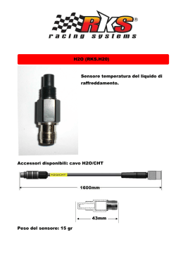
IF400 - IF400/P
sensore infrarosso via radio multibanda
multiband wireless infrared detector
DESCRIZIONE / description
manuale
Installatore
INSTALLATION HANDBOOK
Ver. 1.1
IF400 è un sensore infrarosso, anche pet immune fino a 10kg, via radio con portata 15mt .
Caratteristiche:
- Trasmissione via radio digitale (FSK) ad alta stabilità e precisione.
- Alimentazione con batteria litio standard (tipo CR2) a lunghissima durata .
- Trasmissione a 112 bit a codice variabile (rolling-code) per elevata sicurezza.
- Trasmissione su 3 canali radio per evitare collisioni ed eventuali saturazioni del segnale.
- Supervisionato (life-test automatico).
- Piroelettrico a doppio elemento
- Dispositivo antiapertura (TAMPER).
- 4 funzioni (attivabili mediante DIP-SWITCH) utili per diminuire ulteriormente il consumo del dispositivo e
aumentare l’autonomia (RISPARMIO ENERGETICO).
IF400 is a 15mt range infrared wireless detector, also pet immune 10kg.
Features:
- Digital Radio Transmission (FSK) that gives high precision and stability;
- Standard Lithium Battery supply (CR2 type) for long life;
- 112 bits Rolling-CodeTransmission for high security;
- 3 Channels Radio Transmission to avoid signal collisions and saturation;
- Supervised (Automatic Life-Test);
- Double Element PIR Sensor;
- Antiopening protection device (TAMPER).
- 4 functions (activable by DIP-SWITCH) suitable to additionally reduce the device’s consumption and
increase its autonomy (POWER SAFE)
www.amcelettronica.com
1
IF400 IT-EN v1.1
scheda - collegamenti / board - connections
TASTO LERAN = Premere per far eseguire la lettura di evenuali modifiche dei DIP SWITCH, usato anche
come segnale di autoapprendimento (memorizzazione).
SWITCH TAMPER = Oltre a fare da protezione antiapertura, è utilizzato per riattivare la funzione di test.
TRIMMER PORTATA = Al minimo (trimmer tutto in senso antiorario) la portata è di circa 3mt, regolato al
massimo (trimmer tutto in senso orario) la portata è di circa 13mt
LEARN BUTTON = Press to refresh the DIP SWITCH configuration, it can also be used as learning signal.
TAMPER SWITCH= In addition to the anti.opening protection, it’s used to reactivate the TEST function.
RANGE TRIMMER = At the minimum (anti-clockwise direction) the range is about 3mt, at the maximum
(clockwise direction) the range is about 13mt.
batteria / battery
learn
trimmer portata / range
dip-switch
dip switch
IMPORTANTE: Dopo aver impostato i DIP premere per almeno 1 secondo il tasto LEARN.
IMPORTANT: After DIP SWITCH adjustments press at least 1 second the LEARN button.
DIP1: supervisone
DIP1: Supervision
OFF= 3 ore
OFF= 15 Minutes
ON = 15 minuti
ON = 3 Hours
DIP2: Led Disable
DIP2: Led Disable
OFF = led funzionante
OFF = LED Enabled
ON = led disabilitato
ON = LED Disabled
DIP3: Potenza di trasmissione
DIP3: Transmission’s Power
OFF : potenza massima
OFF : Maximum Power
ON : potenza dimezzata
ON : Halved Power
DIP4 : doppio impulso
DIP4 : Double Pulse
OFF: singolo impulso
OFF: Single Pulse
ON : doppio impulso
ON : Double Pulse
www.amcelettronica.com
IF400 IT-EN v1.1
2
DESCRIZIONE del funzionamento / Operating description
FUNZIONAMENTO IN TEST: Ogni rilevazione è indicata dall’accensione del led rosso per 1 secondo.
Dopo la prima rilevazione con relativa trasmissione del segnale radio, inizia un tempo di conteggio di 10/20
secondi durante il quale il sensore cercherà di rientrare nello stato di riposo. Ogni movimento minimo
rilevato durante questo periodo di tempo manterrà il sensore attivo evitando il rientro nello stato di riposo.
Se al contrario durante questo periodo non rileverà alcun movimento tornerà allo stato di riposo (emettendo
un breve lampeggio) pronto per inviare un segnale causato da un movimento. Lo stato di test è inserito
automaticamente durante la prima accensione, la durata è di 20 cicli; il sensore non andrà a riposo ma si
ripristinerà (10/20secondi ogni violazione) per un totale di 20 volte. Dopo tale conteggio, se viene violato
durante il ripristino ,il sensore andrà in stand-by per circa 2min30sec. Per riportare il sensore in modalità
test basta semplicemente aprire e poi richiudere lo switch di tamper antiapertura.
FUNZIONAMENTO NORMALE: Finita la fase di test, (20 cicli di trasmissioni senza andare in stand-by)
dopo la prima rilevazione con relativa trasmissione del segnale radio, inizia il tempo di conteggio di 10/20
secondi durante il quale il sensore cercherà di rientrare nello stato di riposo. Se al termine del conteggio il
sensore non sarà rientrato nello stato di riposo, a causa di continue rilevazioni, verrà avviato un periodo di
inibizione della durata di 2.5 minuti a bassissimo consumo, durante il quale il sensore non potrà più inviare
segnali radio di allarme di rilevazione (rimanendo comunque attivo per tutte le altre segnalazioni). Ogni
movimento rilevato durante il periodo di inibizione prolungherà lo stesso di altri 2.5 minuti. Per riportare il
sensore in modalità test basta semplicemente aprire e poi richiudere lo switch di tamper antiapertura.
TEST MODE WORKING: Each detection is notified by the LED activation for 1 second. After the first detection and its relative transmission of the radio signal, begins a counting time of 10/20 seconds during which
the detector will try to return in the rest state. Every minimum movement detected during this period of time
will maintain the detector active avoiding the return in the rest state. If, on the contrary, during this period it
doesn’t detect any movement it will return to the rest state ready to send a signal caused by a movement.
The return to the rest state is notified by a LED’s very fast blink, almost imperceptible to optimize the batterie’s consumption. The test mode is automatically activated during the first ignition, the duration is 50 cycles,
the sensor will not rest but it will restore (10/20 seconds each violation) for a total of 50 times. After the
counting, if it is violated during the restoration, the detector will stand-by for about 2min30sec. To return the
sensor in test mode simply open and then reseal the anti-opening tamper switch.
NORMAL MODE WORKING: Finished the test phase (50 cycles of transmission without going in stand-by),
after the first detection with radio signal transmission, begins the counting time of 20 seconds during which
the detector will try to return in the rest state. If, at the end of counting, the detector will not be returned in
the rest state, due to continuous detections, will start a 2.5 minutes period of inhibition in POWER SAFE
mode, during which the detector can no longer send alarm detection radio signals (anyway it remains active
for all other alerts). Each movement detected during the period of inhibition will prolong the same other 2.5
minutes. The end of the period of inhibition is indicated by a LED’s fast blink.
2. Installazione / Installation
Utilizzando uno strumento sottile spingere il tastino tondo sul lato anteriore del sensore (vedi figura 1) e
aprire la cover. Rimuovere la scheda elettronica dal fondo della cover facendo leva sulla clips lato morsetti
,forare gli sfondabili che si desidera utilizzare per il fissaggio, oppure utilizzare l’apposito snodo (opzionale).
Altezza consigliata per il fissaggio 2m.
Per memorizzare il dispositivo sul ricevitore, inserire la batteria nell’apposito vano, seguendo la giusta
polarità, dopodichè utilizzare il tasto LEARN per inviare il segnale di memorizzazione. Per rendere attive
le impostazioni dei dip -switch,una volta configurate, è necessario premere brevemente il tasto LEARN, e
verificare che il led faccia dei lampeggi rapidi. Una volta posizionato il dispositivo nella sede desiderata,
usare i tool di test del ricevitore, per verificare la portata radio, la perfetta chiusura del contenitore, lo stato
della batteria ecc.
By using a thin instrument, push the round button on the front of the detector (see Figure 1) and open the
cover. Remove the electronic board from the bottom of the cover by acting on the terminal side clip. Perforate the knockouts you want to use for fixing, or use the optional swivel bracket.
Note:The recommended height for fixing is 2m.
To program the device into the receiver, insert the battery in the proper space, following the right
polarity, and then use the LEARN Button to send the Learning Signal to the receiver.
To let become active the DIP-SWITCH configuration press the LEARN Button and check if the LED
blinks fast. Once placed the device in the desired position please use the Receiver’s Test Tools to
check the radio range, the perfect box closure, the battery level etc.
www.amcelettronica.com
3
IF400 IT-EN v1.1
Led WALK TEST
Lente / Lens
Premere qui per aprire
Press here to open
Sfondabili per fissaggio
Mounting knockouts
Fissaggio circuito
Clip for electronic board
technical features
IF 400
Batteria / Battery
Consumo / Consumption
Anti-opening
Accessori / Accessories
Portata PIR / PIRRange
Frequenza trasmissione / Operating Frequency
portata campo aperto / Open Space range
Condizioni ambientali / Environmental Conditions
Lithium Ions type CR2
6.5 µA - 17mA
✔
Wall Mounting Swivel Bracket
13mt
433,92 MHz
200mt
from +5°C to +40°C
PET
IMMUNE
VISTA
LATERALE
VISTA IN PIANTA
45°
NORMAL
0°
L’installazione deve essere eseguita a regola d’arte da personale specializzato.
Il produttore declina ogni responsabilità
nel caso in cui il prodotto venga manomesso da persone non autorizzate.
Copertura minima
Si raccomanda di verificare il corretto funzionamento del sistema d’allarme almeno una volta al mese, tuttavia un sistema
Copertura massima
di allarme elettronico affidabile non
evita intrusioni, rapine, incendi o altro, ma si limita a diminuire il rischio che tali situazioni si verifichino.
AMC Elettronica S.r.l. refuses any responsibility when changes or unauthorized repairs are made to the45°
product/system.
It is recommended to test the operation of the alarm product/system at least once a month. Despite frequent testing and
due to, but not limited to, any or all of the following: tampering, electrical or communication disruption or improper use, it
is possible for the product/system to fail to prevent burglary, robbery, fire or otherwise. A properly installed and maintained
alarm system can only reduce the risk that this happens.
www.amcelettronica.com
4
IF400 IT-EN v1.1
Scaricare