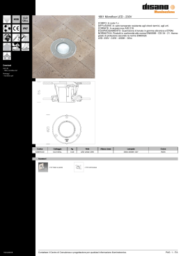
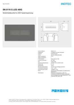
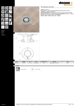
E
N
G
L
I
S
H
I
T
A
L
I
A
N
O
user
ma
nu
ns
tal
laz
io
ne
al
QK-CE220BATRLE
CONTROL BOARD FOR 1/2 230V ac SINGLE-PHASE MOTORS
SCHEDA DI COMANDO PER 1/2 MOTORI MONOFASE 230V ac
i
ll’
a
a
guid
230V
433,92 MHz
PLUG &
PLAY
V3
CONTENTS
INTRODUCTION
3
MAIN FEATURES OF THE CONTROL BOARD
3
TECHNICAL DATA
3
INSTALLATION
3
LAYOUT AND CONNECTIONS
4
OTHER SETTINGS
5
RADIORECEIVER SETUP
5
SETUP
6
FINAL TESTING
7
TROUBLESHOOTING
7
DECLARATION OF COMPLIANCE
8
®
QUIKO GUARANTEE: GENERAL CONDITIONS
9
INTRODUCTION
This manual is enclosed with control unit QK-CE220BATRLE and may not be used for different products. Moreover it
has been especially written for use by qualified fitters.
Important note:
disconnect the panel before operating on the control unit.
QK-CE220BATRLE control unit has been designed to control electromechanical gear motors such as swing gates.
Any other use is considered improper and is consequently forbidden by current laws. The automation system you
are going to install is classified as “machine construction” and is therefore included in the application of European
directive 89/392 EEC (Machinery Directive).
The above mentioned directive includes following prescriptions:
only trained and qualified personnel should install the equipment;
the installer must first make a “risk analysis” of the machine;
the equipment must be installed in compliance with the regulations in force;
after installation, the machine owner must be given the “declaration of compliance”.
Quiko Italy observes all security standards in any phase of the product’s production process (see the attached
declaration of compliance) and the installer must therefore observe the same standards when installing the system.
Should he ignore such regulations, he will be fully responsible for any damage caused by the system. For this
reason we suggest to read all instructions in this manual in advance.
MAIN FEATURES OF THE CONTROL BOARD
Motor torque adjustment
Built-in flashing light circuit with opening (fast) / closing (slow) / pause (always on) differentiated flashing
Built-in radio receiver with 200 memories (2 channel: channel 1 START, channel 2 PEDESTRIAN
START)
Input status LEDs
Protection fuses
2nd “pedestrian entry” function
Soft start/stop function
Plug and play technology
TECHNICAL DATA
Power
Maximum power
Line fuse
Logic circuit fuse
Accessories fuse
Motor output
Electrical lock output
Accessories output
Logic circuit input
Operating temperature
IP protection rate
230Vac 50/60Hz
About 1KW
F1
3,15 A delayed
F2A 500 mA
F3
1,6A
230V ac
12Vac 15W
24Vac 500mA
5Vdc
-20°C / +70°C
IP 55
INSTALLATION
-
-
Position the control board as near as possible the gear motor, in order to avoid over long connection
cables;
Use power cables (power input, motors, earth and flashing light) of at least 1.5 mm 2 conductor, taking
into consideration the amperage, voltage drop and length. This requirement doesn’t apply to the
connection cables of the auxiliary control devices such as key switch and photocell, whose cross-section
can reduced to 0,5 mm2;
Ensure connections to the terminal board are made not to alter the level of protection offered by the
housing, which must be installed in a dry and suitable place according to the IP rating;
PLEASE REMEMBER TO PROPERLY EARTH THIS PRODUCT AND TO OBSERVE THE SAFETY
REGULATIONS IN FORCE IN THE COUNTRY OF INSTALLATION.
3
E
N
G
L
I
S
H
LAYOUT AND CONNECTIONS
DIP SWITCHES for SETUP
JP1 Jumper for SETUP
RADIO PROG.
button for
transmitters
programming
BREAK TRIMMER for
Break/pause time setting
COMMON
STOP
SWITCH
COMMON
OPEN/CLOSE SWITCH
KEY SELECTOR
NOT USED
NOT USED
POWER TRIMMER
for Power / force
setting
EXTERNAL
PHOTOCELLS
INTERNAL
PHOTOCELLS
Connector N°
COMMON
COMMON
CLOSE OPEN
OPEN
230V 50/60Hz
CLOSE
M1
M2
MOTOR
MOTOR
CAPACITOR
CAPACITOR
LD0
LD1
LD2
LD3
LD4
LD5
LD6
LD7
LD8
LD9
Mains supply led
Radioreceiver status led
Start signal led
Pedestrian start signal led
Internal photocell led
External photocell led
Stop signal led
Not used
Not used
Control board status led (it flashes when the
automation is moving)
FLASHING LIGHT 230Vac
Description
Type
Bypass if not
used?
-
1-2
Antenna (1 signal, 2 screen)
-
3-5
Open/close switch and key selector
N.O.
NO
4-5
Pedestrian open/close switch
N.O.
NO
6-9
Internal Photocells. If excited this contact causes: DURING OPENING --> immediate stop of the gate
N.C.
and resume opening upon removal of the obstacle. DURING CLOSING --> immediate stop of the gate
and resume opening. DURING PAUSE --> rejecting of start signals and recharge of pause time.
YES
7-9
External Photocells. If excited this contact causes: DURING OPENING --> No effects. DURING
N.C.
CLOSING --> immediate stop of the gate and resume opening. DURING PAUSE --> recharge of pause
time
YES
8-9
Stop switch
N.C.
YES
12-14
Photocells and accessories output 24Vac 500mA
-
-
13-14
Electrical lock output 12Vac 15W
-
-
15-16-17
Motor 1 output (FIRST MOTOR TO OPEN) 230Vac single phase, connector 16 = common, connectors
15-17 motor feeding and capacitor
-
-
18-19-20
Motor 2 output 230Vac single phase, connector 19 = common, connectors 18-20 motor feeding and
capacitor
-
-
21-23
Flashing lamp output 230Vac
-
-
Control board power supply 230Vac 50/60Hz
-
-
23-24
4
E
N
G
L
I
S
H
+
!
2
3
4&$
$
8
!"#
$
*
"
55
/
!
6
))
6
7
!
6
7
))
6
'
!
6
'
))
6
9
!
6
9
))
6
*
:;
55
/ 1
5
7<1
5.
=#<
$
!
!(
%
#
))
!
*
"
#
$
%
&
#
$
%
&
%
%
'
&
%&
&&
%
%
&
%
%
'
&
%&
&&
%
%
&
)!+
REMOTERECEIVERSETUP
,
(it is necessary to have a remote control
whichisalreadymemorizedinthereceiver)
Entertherayofactionofthereceiverwitha
remote control already memorized and
maintain pressed two buttons of the same
untilthelightingoftheflashinglamp.
$
-%
$$.&/
'#
0
*
(
*
&&/
*
1
Pressthedesiredbuttonofthenewremote
tobememorized.
The flashing lamp flashes to confirm the
memorizationofthenewremote.
1
&2
(
$
/
&
*
$$1
To cancel a single remote control from the
receiver, simply repeat memorization of the
same.
5
DIP3toOFF=preflashingenabled
DIP3toON=preflashingdisabled
6
E
N
G
L
I
S
H
FINAL TESTING
Once all connections have been done and the gate is closed, check that LEDs status is as follows:
LED STATUS TABLE
LD0
LD1
LD2
LD3
LD4
LD5
LD6
LD7
LD8
LD9
ON
OFF
OFF
OFF
ON
ON
ON
OFF
OFF
OFF
TROUBLESHOOTING
Problem
Solution
The LD0 led isn't switched ON so the control board isn't
supplied with electricity
F1 or F2A fuses are fired or not properly inserted. Please check
A START command doesn't let the automation start
230Vac (connectors 23 and 24) aren't connected. Please check.
Check that leds behaviour is as per the LED STATUS TABLE. Otherwise check connections
Check that on every START command the led LD2 switches ON. Otherwise memorise again the
remote button on the radio receiver or check key selector connections
Check that POWER TRIMMER is settled at least at the 2/3 of regulation
Reverse M1 motor cables to reverse the sense of rotation of the motor
A START command let the flashing light start but doesn't Check M1 motor connections
let the automation start
If a electrical lock is installed, check that it is released properly once the gate is opening
Check that the 12Vdc common isn' t connected with the 24Vac
The remote cannot be memorised on the receiver
Take the antenna cables off and try again.
Change the battery of the remote and try again.
7
E
N
G
L
I
S
H
QUIKO® GUARANTEE: GENERAL CONDITIONS
Quiko® products’ guarantee lasts 24 months from the date of purchase of the products (as proved by
the sale document, receipt or invoice, which must be attached to this guarantee).
This guarantee covers the repair with free replacement (ex-works Quiko Italy: packing
and transport at the customer’s expense) of parts that Quiko Italy recognises as being faulty
with regard to workmanship or material.
For home-interventions, also during the guarantee period, a “call-out fee” will be charged for
travelling expenses and labour costs.
The guarantee does not cover the following cases:
v
if the fault was caused by an installation that was not performed according to the instructions
provided by the company inside the product pack;
v
if original Quiko® spare parts were not used to install the product;
v
if the damage was caused by an Act of God, tampering, overvoltage, incorrect power supply,
improper repairs, incorrect installation, or other reasons that do not depend on Quiko®;
v
if a specialised maintenance man does not carry out routine maintenance operations according
to the instructions provided by the company inside the product pack.
The repair or replacement of pieces under guarantee does not extend the guarantee period.
9
10
11
11
1095 Budapest, Mester u. 34.
Tel.: *218-5542, 215-9771, 215-7550,
216-7017, 216-7018 Fax: 218-5542
Mobil: 30 940-1970, 20 949-2688
1141 Budapest, Fogarasi út 77.
Tel.: *220-7940, 220-7814, 220-7959,
220-8881, 364-3428 Fax: 220-7940
Mobil: 30 531-5454, 30 939-9989
E-mail: [email protected] Web: www.delton.hu
www.kaputnyitunk.hu
The Manufacturer can technically improve
the quality of its products without
any prior notice.
Il Fabbricante può apportare ai suoi prodotti
della qualità, senza preavviso.
ma
nu
I
T
A
L
I
A
N
O
e
al
o
us
d’
QK-CE220BATRLE
SCHEDA DI COMANDO PER 1/2 MOTORI MONOFASE 230V ac
230V
433,92 MHz
PLUG &
PLAY
V3
3
3
3
3
4
5
5
6
7
7
8
9
INTRODUZIONE
Il presente manuale è allegato alla centralina QK-CE220BATRLE e non deve essere utilizzato per altri prodotti.
Inoltre, è da intendersi destinato a tecnici qualificati per l’installazione dell’impianto.
Note importanti:
Prima di effettuare interventi sulla centralina si raccomanda di staccare l’alimentazione di rete.
La centralina QK-CE220BATRLE è progettata per il controllo di motoriduttori elettromeccanici quali battenti. Ogni altro
uso è improprio e dunque vietato dalle normative vigenti. L’automazione che state per installare è classificata come
“costruzione di una macchina” e quindi ricade nel campo d’applicazione della direttiva Europea 89/392 CEE
(Direttiva Macchine).
La direttiva sopramenzionata prevede che:
l’installazione deve essere eseguita solo da personale qualificato ed esperto;
chi esegue l’installazione dovrà preventivamente eseguire l’analisi dei rischi della macchina;
l’installazione dovrà essere fatta applicando le Norme in vigore;
infine dovrà essere rilasciata dal proprietario della macchina la dichiarazione di conformità.
Quiko Italy rispetta le normative di sicurezza durante tutto il processo produttivo del prodotto (vedere
dichiarazione di conformità allegata alla fine del presente manuale) ed è quindi implicito che anche l’installatore
debba rispettare scrupolosamente tali norme. Nel caso in cui l’installatore non rispetti le norme in vigore, egli sarà
completamente responsabile degli eventuali danni causati. A tal fine, si consiglia perciò di leggere attentamente
tutte le istruzioni contenute nel presente manuale prima di procedere all’installazione.
CARATTERISTICHE PRINCIPALI DELLA SCHEDA
regolazione coppia motore
lampeggio incorporato differenziato in apertura (veloce) / chiusura (lento) / pausa (sempre acceso)
ricevente radio a bordo con 200 memorie (bicanale: canale 1 START, canale 2 START PEDONALE)
stato degli ingressi visualizzato da led
protezione ingresso linea con fusibile
funzione ingresso pedonale
rallentamento in chiusura e in apertura
tecnologia plug and play
CARATTERISTICHE TECNICHE
Alimentazione scheda
Potenza uscita max
Fusibile ritardato di linea
Fusibile rapido protez. logica
Fusibile rapido protez. Alim. accessori
Tensione circuito d’alimentazione
Uscita serratura
Tensione alimentazione circuito dispositivi ausiliari
Tensione alimentazione circuiti logici
Temperatura di funzionamento
Grado di protezione del contenitore
230V ac 50/60 Hz
1KW circa
F1 3,15A
F2A 500 mA
F3 1,6A
230V ac
12V ac / 15W
24Vac 500mA
5Vdc
-20°C / +70°C
IP 55
INSTALLAZIONE
-
-
posizionare la scheda il più vicino possibile al motoriduttore, per evitare cavi di collegamento troppo
lunghi;
selezionare cavi di potenza (alimentazione, motori, massa e lampeggiante) di almeno 1,5 mm 2 di
sezione, in relazione agli assorbimenti e alla lunghezza dei conduttori. Unica eccezione è da farsi per la
sezione dei cavi di collegamento dei dispositivi di comando ausiliari, la quale potrà avere una misura
minima di 0,5 mm2;
collegarsi alla morsettiera in modo da non alterare il grado di protezione offerto dal contenitore, il quale
deve essere posto in un luogo asciutto e riparato;
SI RICORDA INOLTRE LA NECESSITA’ DI METTERE OBBLIGATORIAMENTE L’IMPIANTO A
MASSA, FACENDO FEDE ALLE NORMATIVE DI SICUREZZA IN VIGORE.
3
I
T
A
L
I
A
N
O
DIP SWITCH
Impostazione
programma
COLLEGAMENTI E SETTAGGI
Jumper JP1 per l’accesso alla
programmazione
Pulsante RADIO
PROGR.
apprendimento
codice radio
TRIMMER BREAK
per regolazione
tempo sosta
PULSANT E APRE-CHIUDE
SELET TORE A CHIAVE
NON USATO
NON USATO
TRIMMER POWER
per Regolazione
coppia / forza
COMUNE
PULSANT E
STOP
FOT OCEL L UL E
EST ERNE
COMUNE
a pr e
c omune
comun e
c h i ude a pr e
c hiude
M1
M2
MOT ORE
MOT ORE
CONDENSAT ORE
CONDENSAT ORE
LD0
LD1
LD2
LD3
LD4
LD5
LD6
LD7
LD8
LD9
230V 5 0/60 Hz
L A MPEGGIA N T E 2 30 Va c
led alimentazione
led stato radioricevente
led di start
led di start pedonale
led fotocellula interna
led fotocellula esterna
led di stop
Non usato
Non usato
led di stato centralina (si accende
quando l’automazione è in movimento)
FOT OCEL L UL E
I NT ERNE
N°
morsetto
1-2
3-5
4-5
6-9
Descrizione
Tipo
Ingresso antenna (1 segnale, 2 schermo)
Pulsante apre-chiude e selettore a chiave
Pulsante start pedonale
Contatto fotocellule interne. Quando eccitato, il contatto provoca: IN APERTURA --> arresto immediato e
ripresa del movimento in apertura alla rimozione dell’ostacolo. IN CHIUSURA --> arresto immediato e
ripresa del movimento in apertura. IN PAUSA --> nessuna accettazione comandi
di start e ricarica tempo di sosta
Contatto fotocellule esterne. Quando eccitato, il contatto provoca: IN APERTURA --> nessun effetto. IN
CHIUSURA --> arresto immediato e ripresa del movimento in apertura indipendentemente dalla presenza
dell’ostacolo. IN PAUSA --> ricarica tempo di sosta
Normalmente aperto
Normalmente aperto
Normalmente chiuso
Ponticellare se
non usato?
NO
NO
SI
Normalmente chiuso
SI
8-9
Pulsante di stop
Normalmente chiuso
SI
12-14
13-14
15-16-17
-
-
18-19-20
21-23
Uscita 24Vac 500mA max (per alimentazione fotocellule ed altri dispositivi)
Collegamento elettroserratura 12Vac 15W
Collegamento motore 1 (primo motore ad aprire) 230Vac monofase, morsetto 16 comune, morsetti 15-17
marcia motore e collegamento condensatore
Collegamento motore 2 230Vac monofase, morsetto 19 comune, morsetti 18-20 marcia motore e
Collegamento lampeggiante 230Vac
23-24
Alimentazione 230Vac +/- 10% 50Hz
-
-
7-9
4
# #-56! #
.
/
4.
4/
.
/
%#
0#""
1
!2 ' !++2" ' 32 ' 3++2" ' &
!2 ' #
&++2" ' #
72 ' #
7++2" ' #
%#
89#""
1:
3;:<=$;
I
T
A
L
I
A
N
O
.
/
# !"
!"*"##"#"
%""#'#
#!$#" " " #"#
#!$#"
" "#" #"#
!%%&'# #(
#)))#" " " #"#
!%%&'# #(
#)))#" " "#" #"#
+
PROGRAMMAZIONEREMOTADEL
RICEVENTE
(è necessario essere in possesso di un
telecomando già memorizzato nella
radioricevente)
Entrare nel raggio d’azione della
radioricevente con un telecomando già
memorizzato e mantenere premuti due tasti
qualsiasi di questo telecomando sino
all’accensionedellampeggiante.
Premeresultelecomandodamemorizzareil
pulsantedesiderato.
Il lampeggiante lampeggia a confermare
l’avvenuta memorizzazione del nuovo
telecomando.
# !"*"###"%
""#' #*"##,- ##"#
%"( ' Per cancellare un singolo telecomando
dalla ricevente è sufficiente ripetere la
memorizzazionedellostesso.
5
DIP3inOFF=prelampeggioattivato
DIP3inON=prelampeggiodisattivato
6
COLLAUDO
A collegamento ultimato e cancello chiuso, controllare che lo stato dei led sia come da tabella
seguente:
TABELLA STATO DEI LED
LD0
LD1
LD2
LD3
LD4
LD5
LD6
LD7
LD8
LD9
I
T
A
L
I
A
N
O
ON
OFF
OFF
OFF
ON
ON
ON
OFF
OFF
OFF
POSSIBILI ANOMALIE E SOLUZIONI
Anomalia
Soluzione probabile
Il led LD0 non è acceso e quindi la centralina non è
alimentata
Uno dei fusibili F1 o F2A non è inserito correttamente o è bruciato. Controllare.
Linea 230Vac (morsetti 23 e 24) non collegata. Controllare.
Verificare che lo stato dei led sia come da paragrafo COLLAUDO. In caso contrario controllare i
collegamenti.
Il comando di START non fa partire l'automazione
Verificare che ad ogni comando di START si accenda il led LD2. In caso contrario riprogrammare il
telecomando sulla ricevente o controllare il collegamento del selettore a chiave.
Verificare che il TRIMMER POWER sia posizionato almeno ai 2/3 della regolazione.
Provare a invertire i fili del motore M1 per invertire il senso di rotazione del motore
Il comando di START fa partire il lampeggiante ma non
l'automazione
Controllare i collegamenti del motore M1
Se è presente elettroserratura verificare che ad inizio movimento venga sganciata
Verificare che il comune 12Vdc non sia collegato al 24Vac
Il telecomando non viene memorizzato dalla
radioricevente
Scollegare il cavo dell'antenna (centrale o segnale) e ritentare la memorizzazione
Sostituire la batteria del telecomando e ritentare la memorizzazione
7
GARANZIA QUIKO®: CONDIZIONI GENERALI
La garanzia sui prodotti Quiko® ha durata di 24 mesi dalla data d’acquisto dei prodotti (fa fede il
I
T
A
L
I
A
N
O
documento fiscale di vendita, scontrino o fattura, che deve essere conservato allegato alla
presente).
La garanzia comprende la riparazione con sostituzione gratuita (franco sede Quiko Italy
: spese d’imballo e di trasporto sono a carico del cliente) delle parti che presentano difetti di
lavorazione o vizi di materiale riconosciuti dalla Quiko Italy.
In caso d’intervento a domicilio, anche nel periodo coperto da garanzia, l’utente è tenuto a
corrispondere il “Diritto fisso di chiamata” per spese di trasferimento a domicilio, più manodopera.
La garanzia decade nei seguenti casi:
v
qualora il guasto sia determinato da un impianto non eseguito secondo le istruzioni fornite
dall’azienda all’interno d’ogni confezione;
v
qualora non siano stati impiegati tutti componenti originali Quiko® per l’installazione
dell’automatismo;
v
qualora i danni siano causati da calamità naturali, manomissioni, sovraccarico di tensione,
alimentazione non corretta, riparazioni improprie, errata installazione, o altre cause non
imputabili alla Quiko Italy;
v
qualora non siano state effettuate le manutenzioni periodiche da parte di un tecnico
specializzato secondo le istruzioni fornite dall’azienda all’interno d’ogni confezione.
La riparazione o la sostituzione dei pezzi durante il periodo di garanzia non comporta un
prolungamento del termine di scadenza della garanzia stessa.
9
10
11
11
1095 Budapest, Mester u. 34.
Tel.: *218-5542, 215-9771, 215-7550,
216-7017, 216-7018 Fax: 218-5542
Mobil: 30 940-1970, 20 949-2688
1141 Budapest, Fogarasi út 77.
Tel.: *220-7940, 220-7814, 220-7959,
220-8881, 364-3428 Fax: 220-7940
Mobil: 30 531-5454, 30 939-9989
E-mail: [email protected] Web: www.delton.hu
www.kaputnyitunk.hu
The Manufacturer can technically improve
the quality of its products without
any prior notice.
Il Fabbricante può apportare ai suoi prodotti
della qualità, senza preavviso.
~
Scarica