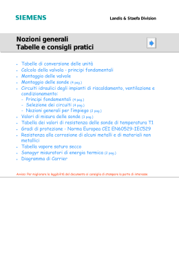
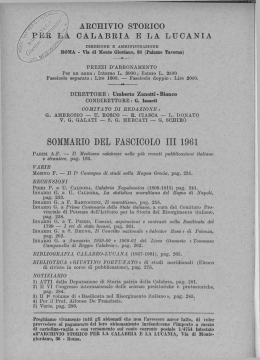
English
Italiano
REGHEL CONTROLLER
MANUALE
OPERATIVO E TARATURE
OPERATIVE GUIDE WITH ADJUSTMENTS
Macchina
REGOLATORE RS100P 350 - 800
con MICROPROCESSORE per controllo POMPA di sollevamento
Machine
AZIENDA CERTIFICATA ISO 9001
SCR PUMP controller RS100P 350 - 800
with MICROPROCESSOR
ENERGY
s.r.l.
Via Roma 10 - 23848 OGGIONO (LC) ITALY
TEL.0039 - 0341-57 87 82 - FAX. 0341-578693
eMail: [email protected]
http: //www.energylecco.it
GENERAL INDEX
INDICE GENERALE
CAPITOLO
1
CHAPTER
1
Descrizione ......................................................... Pag.4
Description ......................................................... Page 4
Descrizione ..........................................................
Applicazioni ..........................................................
Caratteristiche principali .......................................
Dimensioni meccaniche .......................................
Tarature ................................................................
Description ...........................................................
Applications ..........................................................
Main features .......................................................
Mechanical dimensions ........................................
Adjustments .........................................................
CAPITOLO
Pag.4
Pag.4
Pag.4
Pag.5
Pag.5
2
CHAPTER
Page 4
Page 4
Page 4
Page 5
Page 5
2
Schemi elettrici .................................................. Pag.7
Electrical schemes ............................................. Page 7
Schema RS100P pompa con PCC3P .................. Pag.8
Schema RS100P con PCC3P .............................. Pag.9
Scheme RS100P pump with PCC3P ................... Page 8
Scheme RS100P with PCC3P ............................. Page 9
CAPITOLO
3
CHAPTER
3
Ricerca guasti .................................................... Pag.10
Trouble shooting ................................................ Page 10
Ricerca guasti ...................................................... Pag.10
Trouble shooting .................................................. Page 10
Descrizione
REGHEL CONTROLLER
Description
1
Capitolo
Chapter
APPLICAZIONI
APPLICATIONS
Regolatore di corrente per motori pompa in corrente
continua.
Speed controller for DC pump motors.
REGOLAZIONI
ADJUSTMENTS
1)
2)
3)
4)
5)
6)
1) Soft start ramp
2) Speed 1
3) Speed 2
4) Power steer min.
speed
5) Power steer max.
speed
6) Power steer
compensation level
7) Power steer delay.
Rampa di accelerazione.
Velocità 1
Velocità 2
Velocità minima idroguida
Velocità massima idroguida
Livello compensazione
idroguida
7) Timer idroguida
CARATTERISTICHE PRINCIPALI
MAIN FEATURES
1) Tecnologia a SCR
2) Ampiezza di pulsazione e frequenza di modulazione. Frequenza massima: 300 Hz.
3) Voltaggio: 24-80V
4) Soft start.
5) Comando d’avvio tramite microinterruttore o
potenziometro.
6) Controllo idroguida con lo stesso motore.
7) Corrente massima: 800A
8) Limitatore di corrente.
1) SCR technology.
2) Pulse width and frequency modulation. Max.
frequency: 300 Hz
3) Rated voltage 24 to 80 Volt.
4) Soft start.
5) Start command by microswitch or potentiometer.
6) Control of power steer available from the same
motor.
7) Max. peak current: 800 Ampere.
8) Current limiter.
MODEL SELECTION GUIDE
MODEL
RS100P350
RS100P400
RS100P450
RS100P500
RS100P550
RS100P600
RS100P700
RS100P750
RS100P800
pag.4
Ampere
Volt supply
350
400
450
500
550
600
700
750
800
24 - 80
24 - 80
24 - 80
24 - 80
24 - 80
24 - 80
24 - 80
24 - 80
24 - 80
1
Capitolo
Descrizione
Chapter
Description
DIMENSIONI MECCANICHE
REGHEL CONTROLLER
MECHANICAL DIMENSIONS
145
NOTA: Tutte le quote in mm.
NOTES: All quotes in mm.
5
16
250
ADJUSTMENTS
TARATURE
PCC3 MICROPROCESSORE
PCC3 ELECTRONIC LOGIC
La scheda PCC3/P Microprocessore consente di agire sulle tarature.
Le tarature previste sono 5
descritte nella tabella.
The PCC3/P control logic with
microprocessor allows control on
adjustments. Five adjustments are
provided as described in the table.
On the front panel there is also a
red LED to signal the type of failure
during operation (see paragraph
“Trouble Shooting” for reference).
E’ previsto anche un LED rosso di diagnostica in grado di
segnare in modo codificato il
tipo di guasto del regolatore (si
veda il paragrafo “Ricerca guasti”)
1) Velocità 1: 0-100 %
2) Tempo della rampa di accelerazione: 0.3 - 5 sec.
3) Velocità 2: 0-100 %
4) Velocità base in funzione
idroguida: 0-40 %
5) Fattore di compensazione
in funzione idroguida: da 1
a 2 (fattore di scala)
1
2
3
4
5
1) Speed 1: 0-100%
2) Acceleration ramp time: 0,3 - 5
sec.
3) Speed 2: 0-100%
4) Power steer basic speed: 040%
5) Power steer compensation
factor: from 1 to 2 (scale factor)
pag.5
Schemi elettrici
REGHEL CONTROLLER
Schema
RS100P POMPA con PCC3P
pag.8
Electrical scheme
2
Capitolo
Scheme
RS100P PUMP with PCC3P
Chapter
B
GI
14
SKA
1
Electrical scheme
Schema
RS100P con PCC3P
MOTORE POMPA
PUMP MOTOR
DIODI
300A
TERMICA
NERO - BLACK
GRIGIO - GREY
NERO - BLACK
VERDE - GREEN
ROSSO - RED
GIALLO - YELLOW
BIANCO - WHITE
MARRONE - BROWN
VIOLA - VIOLET
Chapter
CONDENSATORE DI
FILTRO
4700 µF
200 V.
NERO - BLACK
NERO - BLACK
Capitolo
K1
TELERRUTORE DI LINEA
CONTACTOR LINE
BATTERIA / B ATTERY
2
Schemi elettrici
REGHEL CONTROLLER
Scheme
RS100P with PCC3P
pag.9
Ricerca guasti
Trouble shooting
REGHEL CONTROLLER
3
Capitolo
Chapter
RICERCA GUASTI
TROUBLE SHOOTING
La ricerca dei guasti avvenuti sull’impianto SCR, sulla
scheda PCC3 e sull’impianto esterno (motori, cavi,
batterie, etc.) è estremamente semplificata dall’utilizzo
del MICROPROCESSORE.
The trouble shooting analysis on SCR power board,
PCC3 board, external equipment (D.C. motor, battery,
cables, etc.) is extremely simplified by the
MICROPROCESSOR.
The microprocessor monitors all the working parameters
and the insulation level among the electrically isolated
parts (e.g.: + pole with ground plate) at each internal
clock.
If this test is correct on all parts the microprocessor
gives the appropriate signal to the SCR and power is
transmitted by the equipment.
If faults occurs then the microprocessor halts every
operation and signal with a coded flashing on the led
the kind of failure sensed.
Il MICROPROCESSORE esegue ad ogni ciclo di clock
un controllo di tutti i parametri di funzionamento e sul
livello di isolamento delle parti elettricamente separate
(es. polo positivo con la massa).
Se il test è superato per tutti i controlli, allora il MICROPROCESSORE abilita il pilotaggio degli SCR e
l’erogazione di potenza ai motori.
Se una qualsiasi situazione di allarme è diagnosticata,
il MICROPROCESSORE interrompe il funzionamento
regolare ed indica con un lampeggio codificato il tipo di
anomalia diagnosticata.
ALARM CODE
CODICE STATUS ALLARMI:
Lampeggi
Significato
Flashes
Failure
1)
Anomalia comandi di marcia all'avviamento.
1)
2)
SCR1 in cortocircuito o cortocircuito
esterno B e - .
Foot pedal micro switch already closed on
turning ON key.
2)
SCR in short circuit at starting or external
short circuit B and Negative.
3)
Not codified.
4)
Open motor/Line contactor doesn’t close.
5)
Erroneous working of controller.
6)
Not codified.
7)
Not codified.
3)
Non codificato.
4)
Carico aperto / Teleruttore di linea non chiude
5)
Falsa commutazione.
6)
Non codificato.
7)
Non codificato.
8)
Pilotaggio Teleruttori in corto circuito /
scheda guasta.
6)
Contactors driving in short circuit
9)
Sottotensione di alimentazione 14 Volt scheda, batteria bassa carica.
7)
SCR1 non entra in conduzione
(mancata accenzione).
Low board supply (14 Volt); battery low level
of charge.
8)
SCR1 doesn’t work.
10)
pag.10
Scarica