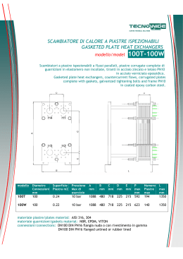
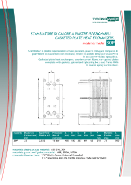
Scambiatori di calore
a piastre ispezionabili
Gasketed plate heat exchangers
F205/F31/F40/F50/F71
07
Scambiatori a piastre ispezionabili con attacco flangiato DN100
Gasketed plate heat exchangers with flanged fitting DN100
Layout connessioni possibili / Layout of allowed couplings
PRIMARIO/PRIMARY
SECONDARIO/SECONDARY
INGRESSO/IN
USCITA/OUT
INGRESSO/IN
USCITA/OUT
F1
F4
F3
F2
F4
F1
F2
F3
F3
F2
F1
F4
F2
F3
F4
F1
Con piastre offset attenersi esclusivamente al layout
indicato nella scheda di calcolo.
Con circuito primario si intende quello più caldo che
cede calore. Con circuito secondario si intende quello
più freddo che prende calore.
With offset plates: strictly respect the layout shown
in the calculation sheet.
By primary circuit it is meant the hotter one which
releases heat.
By secondary circuit it is meant the cooler one which
receives heat.
F2
F4
F3
E
C
F1
A
D
L2
B
PP
* con rubber line NPx3,1+1,5
* with rubber line NPx3,1+1,5
Modello
Diametro
Superficie Pressione A
B
C
D
E
PP
Numero
L2
connessioni
piastra
massima di piastre
esercizio
Model
Coupling
Plate Max. working A
B
C
D
E
PP
Number
L2
diameter
surface area
pressureof plates
F205
m2 DN 100 UNI PN 16 0.21
barmm
mm
16
620
1160 480719225204NPx3.1*NP≤60 60<NP<150 1120
F31
DN 100 UNI PN 16
0.30
16
1332 480894225204NPx3.1* NP≤60620
60<NP≤1501120
F40
DN 100 UNI PN 16
0.40
16
1579 4801141225 204NPx3.1* NP≤60620
60<NP≤1501120
F50
DN 100 UNI PN 16
0.50
16
1826 4801388225 204NPx3.1* NP≤60620
60<NP≤1501120
F71
DN 100 UNI PN 16
0.70
10 - 16 - 25
2320
480
1882
225
204
NPx3.1*
NP≤60600
60<NP≤1501100
150<NP≤2501600
250<NP≤3502100
350<NP≤5002600
500<NP≤6003100
Scaricare