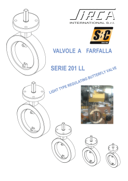
DOUBLE ECCENTRICITY BUTTERFLY
VALVE SERIES 401
VALVOLA A FARFALLA SERIE 401
A DOPPIA ECCENTRICITÀ
This is a range of buttefly valves of the
double eccentricity type with “bubble tight”
seal, designed for heavy duty service, especially as regards shipbuilding and petrochemical sectors. Above all it is ideal for
shut-off and/or flow control of aggressive
fluids or gases. A wide variety of materials
can be used to make the valve; those falling in the standard range are: ductile iron, carbon
steel, stainless steel, aluminium bronze or electrically
welded constructions. Such valves are manufactured
according to the most updated design criteria, thereby offering guarantee of correctoperation and
minimum maintenance.
E’ una gamma di valvole a farfalla del tipo a doppia
eccentricità a tenuta perfetta “bubble tight” progettata per soddisfare servizi pesanti, in particolar
modo quelli relativi al settore navale e petrolchimico. Ideale soprattutto per l’intercettazione e/o regolazione di gas o fluidi aggressivi. Moltecipli sono i
materiali che possono essere impiegati per la
loro realizzazione, quelli che rientrano nella
gamma standard sono: ghisa sferoidale, acciaio
carbonio, acciaio inox, bronzo alluminio oppure
in struttura elettrosaldata. Tali valvole sono realizzate secondo i più aggiornati criteri costruttivi,
assicurando quindi la massima garanzia di buon
funzionamento e la minima manutenzione.
PRINCIPALI SETTORI DI UTILIZZO
•
•
•
•
•
•
•
•
MAIN FIELDS OF APPLICATION
IMPIANTI PETROLCHIMICI
INDUSTRIE FARMACEUTICHE
INDUSTRIE CHIMICHE
INDUSTRIE ALIMENTARI
BIRRERIE
DISTILLERIE
CARTIERE
CANTIERI NAVALI
•
•
•
•
•
•
•
•
PETRO CHEMICAL PLANTS
PHARMACEUTICAL INDUSTRIES
CHEMICAL INDUSTRIES
FOOD INDUSTRIES
BREWERIES
DISTILLERIES
PAPER MILLS
SHIP YARD
CARATTERISTICHE GENERALI
SPECIFICATION
•
•
•
•
•
Prodotta nei diametri DN80÷DN1000 (3“÷40”).
Temperatura di esercizio: -50°C÷200° (-58°F÷392°F)
Montaggio tra flange UNI-ISO-DIN-PN10-PN16-ANSI150RF.
Perfetta tenuta con pressione differenziale 17,5 bar e VUOTO.
Protezione delle parti esterne della valvola dalla corrosione tramite
verniciatura epossidica e/o poliuretanica, nell’esecuzione
ghisa sferoidale o acc. carbonio.
• Bassa coppia statica.
• Azionabile mediante leva manuale parzializzante (10 posizioni) e
riduttore ad ingranaggi irreversibile e volantino-attuatori
pneumatici-attuatori elettrici ecc.
•
•
•
•
INSTALLAZIONE IN LINEA
ON LINE INSTALLATION
• Chiudere il disco della valvola in modo che rimanga all’interno del
corpo valvola.
• Centrare le due flange con il corpo valvola, dopo aver posizionato le
due guarnizioni.
• Serrare la valvola tra le due flange facendo uso dei tiranti parzialmente avvitati, completare poi il serraggio dei dadi procedendo in
ordine incrociato.
• Usare il blocco flangia-valvola-flangia per la preparazione ed il centraggio della tubazione.
• Saldare a punti flange alle relative tubazioni.
• Rimuovere i dadi e i tiranti e sfilare via la valvola.
• Close the valve’s disc so that the disc is in the valve’s body.
• Center the two flanges with the valve’s body after having positioned
the two gaskets.
• Close the valve’s body between the bolts and partially tighten the
bolts, and complete tightening the nuts evently crossed.
• Use the assembled block, flange-valve-flange, for the pipeline
preparation and centrage.
• Spot-weld the flanges to the pipeline.
• Remove the bolts and valve from the flange.
Manufactured in the diameters DN80÷DN1000 (3“÷40”).
Operating temperature: -50°C÷200° (-58°F÷392°F)
Mounting between flanges UNI-ISO-DIN Pn10-Pn16-Ansi150RF.
Perfectly tight shut-off with differential pressure 17,5 bar and
VACUUM.
• Outer valve parts protected against the corrosion by epoxy or
polyurethane paint in ductile iron or carbon steel execution.
• Low static torque.
• Can be actuated by a 10 position leverlock handle-irreversible
reducation gear with handwheel - pneumatic actuators electrical actuators, etc..
INSTALLAZIONE TRA FLANGE - INSTALLATION BETWEEN THE FLANGES
IMPORTANTE:
IMPORTANT:
Non eseguire la saldatura completa della
flangia alla tubazione con la valvola inserita tra le stesse, il calore e i residui di saldatura possono danneggiare la sede di
tenuta.
- Completare le saldature delle flange alle
tubazioni e lasciarle raffreddare completamente.
- Completare l’installazione della valvola
tra le flange seguendo le istruzioni per il
montaggio su tubazioni esistenti (vedi
sopra).
Do not finish welding the flanges to the
pipeline with the valve inserted between
them, as some welding residuals in the
pipeline could damage the body seat.
- Complete the flanges welding and let it
cool completely.
- Install the valve following the
instructions of the existing pipeline installation.
80
Scaricare