MANUALE D'USO E MANUTENZIONE - USER'S MANUAL
code LP66 - LP33 - LP312
LED PANEL - 3000/4000K
Applicazioni: incasso e al plafone.
Installation: recessed and ceiling.
MADE IN P.R.C.
PRODOTTO IN CL.III FORNITO CON KIT IN CL.II PER IL
COLLEGAMENTO DIRETTO ALLA RETE 220-240V - 50/60Hz.
NON COLLEGARE IL LED DIRETTAMENTE ALLA RETE, UTILIZZARE
L'ALIMETATORE IN DOTAZIONE.
PRODUCT IN CL.III SUPPLIED WITH KIT IN CL.II FOR 220-240V 50/60Hz DIRECT CONNECTION.
DO NOT CONNECT LEDs DIRECTLY TO 220V, USE THE POWER
EQUIPMENT
ATTENZIONE: la sicurezza dell’apparecchio è garantita solo con l’uso
appropriato delle seguenti istruzioni; per cui è necessario conservarle.
L’APPARECCHIO
DEVE
ESSERE
INSTALLATO
SOLO
DA
PERSONALE QUALIFICATO. NEL RISPETTO DELLE NORME
D'INSTALLAZIONE NAZIONALI(MERCATO ITALIA LEGGE 46/90).
L’AZIENDA
DECLINA
OGNI
RESPONSABILITA’
QUALORA
L’INSTALLAZIONE NON AVVENGA SECONDO LE NORME
VIGENTI. LASCIARE COPIA DI QUESTE ISTRUZIONI AL
RESPONSABILE DELLA MANUTENZIONE.
CAUTION: fitting safety can be guaranteed only if below instructions
are followed properly. Therefore, they must be kept.
THE FIXTURE MUST BE INSTALLED EXCLUSIVELY BY QUALIFIED
PERSONNEL. THE COMPANY DENIES ANY LIABILITY IN CASE
INSTALLATION IS NOT CARRIED OUT IN COMPLIANCE WITH
CURRENT LAWS.
LEAVE COPY OF THESE INSTRUCTIONS TO MAINTENANCE
PERSONNEL IN CHARGE.
TOGLIERE LA TENSIONE PRIMA DI
EFFETTUARE QUALSIASI TIPO DI MANUTENZIONE.
ENSURE THE POWER IS SWITCHED OFF BEFORE STARTING
MAINTENANCE.
FRAGILE: MANEGGIARE CON CURA
FRAGILE HANDLE WITH CARE
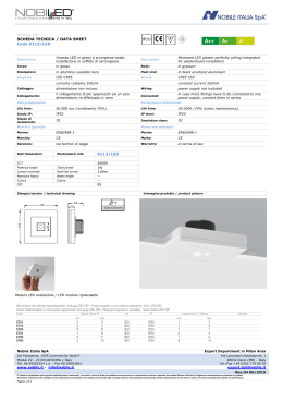
Fasi d'installazione (con supporto per l'alimentatore):
Installation steps (with power supply support):
1
Avvitare l'alimentatore nel supporto per alimentatore con 2 viti
filettate 3x8.
Assicurarsi che l'alimentatore sia ben avvitato al supporto e quindi
usare 2 viti M4x8 per stringere il supporto al pannello.
Screw the power supply into the power supply support by 2pcs of 3x8
self tapping screws.
Make sure the power supply is tight on the support, and then use 2 pcs
of M4x8 screws to fasten the support on the panels.
Collegare l'uscita dell'alimentatore all'ingresso del led panel.
Connect the output end of power supply to the input end of the panel
light.
Caution:
Note the "+" and"-" poles of power supply. ("+" pole,with letters).
Use the screws to hold the wires tightly.
Keep the power off to connect the wires.
Do not apply a lot of pressure to twist the screws and make the
panel light broken.
2
3
Attenzione:
A
Verificare i poli + e - dell'alimentatore (+ in lettere).
B
Utilizzare le viti per tirare saldamente i fili.
C
Staccare la corrente durante la connessione dei fili.
Non premere molto, avvitando le viti, per non rischiare di rompere
D
il pannello.
Nobile Italia SpA
www.nobile.it - [email protected]
Export Sales Department
[email protected]
IS LED PANEL - Rev.05 09/2015
Pagina 1 di 6
4
Collegare il cavo in entrata dell'alimentatore alla corrente AC
Note:
A
Per la messa in sicurezza è necessario l'isolamento elettrico.
B
Staccare la corrente durante la connessione dei fili.
Connect the input end of power supply to AC
Note:
Electric insulating treatment is needed to keep safety.
Keep the power off to connect the wires.
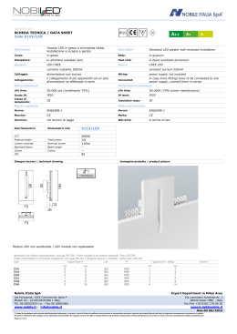
INSTALLAZIONE A CONTROSOFFITTO:
RECESSED INSTALLATION:
1
Installare il pannello nel controsoffitto.
Attenzione:
A
Girare il pannello di 45° e inserirlo nel controsoffitto. Non esercitare
una forte pressione al fine di non danneggiare il pannello.
B
Installarlo per ottenere un bell'effetto di luce
C
Considerare le specifiche di installazione (dimensione) prima di
scegliere il pannello.
Install panel light on the ceiling board.
Caution:
Turn over panel light with 45°and put it on the ceiling board.
Do not press or pass through ceiling board strongly.
Carefully install it so that it get a good lighting effect.
Consider the installation specification(Size) before choose the recessed
panel light.
2
Tenere verso il basso la superficie luminosa del pannello
Take the lighting surface of panel light down.
3
Allineare la superficie del pannello a quella del controsoffitto e
terminare l'installazione.
Aligning the site of panel light and ceiling board and finish the
installation.
Nobile Italia SpA
www.nobile.it - [email protected]
Export Sales Department
[email protected]
IS LED PANEL - Rev.05 09/2015
Pagina 2 di 6
4
Ecco l'immagine dell'installazione completata e la predisposizione
all'accensione.
IMPORTANTE:
A
Finita l'installazione controllare i connettori.
B
Controllare che tutti i connettori + e - siano collegati correttamente.
C
Controllare che le viti siano ben strette.
1
2
3
4
5
The picture for finishing the installation and light it.
IMPORTANCE:
Finish the installation, check the connectors.
Check all connectors' "+" and "-" poles to be connected correctly.
Check the sites with screws are locked tightly or not.
FISSAGGIO ALIMENTATORE PER VERSIONE A
SOSPENSIONE (CON ADESIVO 3M)
FIX THE POWER SUPPLY FOR SUSPENDEND VERSION
Tenere verso l'alto il lato posteriore dell'alimentatore.
Aderire l'adesivo all'alimentatore.
Fare attenzione durante l'installazione perché l'adesivo è forte.
Dopo aver applicato il 3M, premerlo e farlo aderire bene.
Sollevare la pellicola dall'adesivo.
Stato senza la pellicola.
Take the back side of power supply up.
Stick 3M on power supply.
Take care when installation, because 3M adhesiveness is strong.
After post 3M, press it and keep it stick firmly.
Take the surface paper off the 3M.
The status without surface paper.
(WITH 3M TAPE):
INSTALLAZIONE A PLAFONE:
INSTALLATION CEILING:
1
Screw the bracket onto the panel in right position by 4 pcs of M4x8
countersunk head screws, and make sure they’re tight.
Driver to be connected in remote
2
Avvitare la staffa sul pannello nella posizione corretta con 4 viti
M4x8 e assicurarsi che siano ben strette
Alimentatore da collegare in remoto
Nobile Italia SpA
www.nobile.it - [email protected]
Export Sales Department
[email protected]
IS LED PANEL - Rev.05 09/2015
Pagina 3 di 6
3
Fare dei fori di diametro 6mm nel plafone in corrispondenza dei fori
della staffa e inserire i tasselli. Infine stringere le viti 4x30.
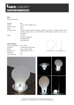
CAVO DI SICUREZZA:
Drill a D6mm hole in the ceiling in accordance with the size of the
bracket, then put the bulge plug in. Finally, use the 4x30 countersunk
head tapping screws to fasten the panel into the holes.
SECURITY CABLE:
1.
Accessori / Accessories
2.
Praticare un foro Ø6mm nel luogo di installazione.
Making a hole Ø6mm in the installation position.
3.
Utilizzando le viti (7) fissare l'accessorio (1) al pannello come
mostrato in figura.
Using screw (7) to fix accessory (1) on panel as showing above.
4.
Inserire il tassello (4) nel foro e avvitare l'accessorio (2) con
la vite (6) come in figura.
Put the expansion rubber plug(4) into the hole on the ceiling
and fix the accessory (2) with screw (6) as showing above.
5.
Far passare il cavo di acciaio negli accessori 3 e 5, uscendo dal foro
dell'accessorio 2. Infine avvitare gli accessori 2 e 5 tra loro.
Pass the steel cable into accessories 3 and 5, going out from the
hole of accessory 2. Finally screw the accessories 2 and 5 between
them.
6.
Sollevare il pannello e collegare gli accessori 1 e 3,
regolando l'altezza del cavo attraverso l'accessorio 5.
Keep the panel and wire the accessories 1 and 3, adjusting
the height of the cable with accessory 5.
7.
Arrotolare il cavo in eccesso.
Wrap up exceeding cable.
Nobile Italia SpA
www.nobile.it - [email protected]
Export Sales Department
[email protected]
IS LED PANEL - Rev.05 09/2015
Pagina 4 di 6
NOTE GENERALI:
GENERAL NOTES:
1
Durante l'installazione, evitare campi magnetici e aree ad alto
voltaggio.
2
Assicurare una solida connessione per evitare che un corto circuito
danneggi i componenti e provochi incendi.
Verificare la tensione in conformità ai requisiti del prodotto prima di
utilizzarlo.
Per evitare cavi scoperti, controllare che i fili siano collegati
correttamente e poi accendere l'apparecchio.
SI PREGA DI NON UTILIZZARE MAI PRODOTTI A LED IN QUALSIASI
LUOGO CON LE SEGUENTI SOSTANZE CHIMICHE:
C12\H2S\NO2\SO2
When installation, try to avoid the minefields strong magnetic field
and high-voltage area.
Ensure a solid connection correctly in order to avoid short-circurt
damage to components and trigger fires.
Please check local voltage in accordance with the product requirements
before using the product.
To prohibit the live wiring, check to confirm the wiring correct, confirm
no short-circuit and then power on.
PLEASE NEVER USE LED PRODUCTS AT ANY PLACE WITH FOLLOWING
CHEMICAL:C12\H2S\NO2\SO2
3
4
5
MORSETTIERA
NON
INCLUSA,
L’INSTALLAZIONE
POTREBBE
RICHIEDERE L’AIUTO DI PERSONALE QUALIFICATO; MORSETTIERE
CONFORME A EN 60998-2-1 O EN 60998-2-2. LA MORSETTIERA DEVE
ESSERE
INSTALLATA
IN
UNA
SCATOLA,
GARANTENDO
LA
CLASSIFICAZIONE IP SECONDO LE NORME DI CABLAGGIO.
TERMINAL BLOCK NOT INCLUDED, INSTALLATION MAY REQUIRE
ADVICE OF QUALIFIED STAFF; TERMINAL BLOCK CONFORM TO EN
60998-2-1 0R EN 60998-2-2.
THE TERMINAL BLOCK SHALL BE INSTALLADE IN A BOX ASSURING IP
CLASSIFICATION ACCORDING TO WIRING RULES.
MORSETTIERA CON VITE - 2 POLI - 250V - 10A
DA FISSARE ADEGUATAMENTE
TERMINAL BLOCK WITH SCREW - 2 TERMINALS - 250V - 10A
TO PROPERLY SECURE
CAVO BLU: NEUTRO (N)
CAVO MARRONE: FASE (L)
BLUE CABLE: NEUTRAL (N)
BROWN CABLE: FASE (L)
Attenzione: se il cavo flessibile esterno di questo apparecchio viene
danneggiato, deve essere sostituito da un cavo speciale disponibile
esclusivamente presso il costruttore o il suo servizio di assistenza.
Be careful: should the external flexible cable of the fitting be damaged,
it must be replaced by a special cable supplied exclusively by the
manufacturer or its service.
Nobile Italia SpA
www.nobile.it - [email protected]
Export Sales Department
[email protected]
IS LED PANEL - Rev.05 09/2015
Pagina 5 di 6
AVVERTENZE GENERALI - GENERAL WARNINGS
I TEMPI E I METODI NECESSARI PER LA MANUTENZIONE DIPENDONO DAL
LUOGO E SITUAZIONE DI MONTAGGIO E DALLE CONDIZIONI AMBIENTALI.
TIMES AND METHODS NECESSARY FOR MAINTENANCE DEPENDS ON PLACE,
ENVIRONMENTAL AND MOUNTING CONDITIONS.
VERIFICARE L’INTEGRITA’ DEI CAVI, DEI PRESSACAVI E DELLE CONNESSIONI.
IN CASO FOSSERO DANNEGGIATI SONO DA SOSTITUIRE CON RICAMBI
CONFORMI ALL’ ORIGINALE.
CHECK CABLES, CABLE GLAND AND CONNECTIONS WHOLENESS. IF THEY ARE
DAMAGED, THEY MUST BE REPLACED IN COMPLIANCE WITH THE ORIGINAL.
IL PRODOTTO E’ IN CLASSE II. NON COLLEGARE LA MESSA A TERRA
THE PRODUCT IS IN INSULATION CLASS II, NOT CONNECT THE
EARTH TERMINAL
PRODOTTI CHIMICI O ACIDI, UTILIZZATI IN FASE DI PULIZIA,
POSSONO
DANNEGGIARE
LA
SUPERICIE
E
PROVOCARE
LA
CORROSIONE ANTICIPATA SIA DELLE CASSAFORME CHE DEGLI
APPARECCHI.
CHEMICAL PRODUCTS OR ACIDS, USED FOR CLEANING, CAN
DAMAGE THE SURFACE OF THE FORMWORK AND THE FITTING,
CAUSING THEIR CORROSION.
APPARECCHI A LED AD INCASSO NEL PLAFONE
Al fine di garantire un corretto funzionamento dei LED, salvaguardandone la
durata e l’efficienza, è necessario che gli apparecchi ad incasso a plafone
vengano installati in modo tale che il corpo dissipante risulti libero,
possibilmente in ambiente arieggiato. Questo per agevolare di svolgere la
propria funzione di irradiare verso l’esterno il calore generato dal
funzionamento del LED. Come parametro di riferimento per definire il livello
massimo di temperatura nell’ambiente circostante è quella indicata sul
rispettivo alimentatore in dotazione con il simbolo Ta. Da verificare con
apparecchio in esercizio. Si raccomanda pertanto, di non coprire o inglobare il
dissipatore con schiume poliuretaniche, resine o con qualsiasi altro materiale
con basse proprietà termo conduttive (legno, plastica, etc.). Inoltre è fatto
divieto posizionarlo direttamente all’interno delle lastre di laterizio della soletta.
LED FITTING FOR CEILING INSTALLATION
In order to ensure a correct LED functioning, safeguarding life time and
efficiency, it’s necessary that ceiling mounted fittings are installed keeping
the heat sink body free, possibly in a ventilated environment.
This is to facilitate its own function to radiate heat generated by LEDs
outwards. Consider the Ta symbol showed on the power supply included to
know the maximum environment temperature level.
This is to be checked with the working fitting. It is suggested neither to
cover the heat sink nor to enclose it in polyurethane foams, resinsor any
other material with low-conductive properties (wood, plastic material, etc.).
Moreover, it is forbidden to put the fitting directly inside the brick slab.
USO DEGLI ALIMENTATORI
Ogni codice prodotto ha indicato, sia nel catalogo generale sia nella scheda
tecnica relativa, quali sono gli alimentatori prescritti dal fabbricante per il
corretto funzionamento. L’utilizzo improprio di alimentatori non corrispondenti a
quanto prescritto può essere causa di malfunzionamento dell’apparecchio. Ciò
esula dalla copertura di garanzia del prodotto, violando le condizioni di
garanzia. La Nobile Italia SpA sarà sollevata da tutti i danni causati
dall’imperizia dell’installatore.
USE OF POWER SUPPLIES
Each product code has marked, both in the general catalogue and in related
data sheet, which are the power supplies suggested by the manufacturer for
the correct functioning of the fitting. The use of different power supplies
than suggested ones can cause malfunctioning of the products. In this case,
as this use violates guarantee conditions, the guarantee will be not valid.
Nobile Italia SpA will not be responsible for damages caused by incorrect
installation.
MANOMISSIONE E MALFUNZIONAMENTO DEGLI APPARECCHI
Nel caso di manomissione degli apparecchi viene a decadere automaticamente
la garanzia di prodotto. Nel caso di malfunzionamento degli apparecchi
segnalare la non conformità al nostro Ufficio Assistenza Tecnica Clienti, il quale
provvederà alla verifica tecnica di com’è stata eseguita l’installazione, verificato
che il tutto è stato eseguito a regola d’arte, sarà emessa autorizzazione al reso,
il prodotto mal funzionante sarà immediatamente sostituito senza addebito di
costi. IL PRODOTTO NON DEVE ESSERE MANOMESSO.
DAMAGING AND MALFUNCTIONING OF FITTINGS
In case of damaging of fittings, product guarantee decays automatically. In
case of malfunctioning of the fittings, inform our Technical Customer Care
Office of the non conformity. Our staff will carry out a technical check about
correct installation phases, then if everything has been done correctly, the
will issue an authorization for returned items and non working
product will be immediately replaced without any charge.
DO NOT DAMAGE THE FITTING
In caso di rottura del vetro, il prodotto non può essere utilizzato; contattare il
costruttore per la sua sostituzione.
In case of broken glass, the product cannot be used; contact the supplier
for replacing it.
DIRETTIVA 2002/96/CE (Rifiuti di Apparecchiature
Elettriche ed Elettroniche – RAEE)
Il prodotto a fine vita deve essere smaltito e riciclato in appositi
centri di raccolta, non può essere smaltito come rifiuto
domestico. Dettagli sui centri di raccolta disponibili c/o ufficio
governativo locale e c/o il rivenditore del prodotto.
DIRECTIVE 2002/96/EC (Waste Electrical and Electronic Equipment
- WEEE)
The product at the end of life must be disposed of and recycled in a
designated collection point, cannot be treated as household waste. Details
on the collection points available c/c local government office or the product
retailer.
Questo apparecchio è stato costruito secondo gli standard europei EN 60598-1 ultima
edizione. Nobile Italia Spa via Portuense 1555, Commercity Isola P - Moduli 22-23 - 00148
Roma Italy - tel. +39-06-65002524r.a – Fax +39-06-65002861 garantisce la qualità del
proprio apparecchio.
This fixture has been manufactured according to European standards EN 60598-1 last
edition. Nobile Italia Spa via Portuense 1555, Commercity Isola P - Moduli 22-23 00148
Roma Italy tel. +39-06-65002524r.a. – Fax +39-06-65002861 guarantees the quality of
its equipment.
E’ vietata la riproduzione anche parziale delle illustrazioni contenutevi. La società si riserva il
diritto di modificare senza preavviso le caratteristiche tecniche e estetiche dei prodotti illustrati
nell’ottica di migliorare costantemente le prestazioni e la qualità.
No pictures contained in this manual may be reproduced, even partially. The company
reserves the right to change the technical and aesthetic characteristics of the products
shown in order to constantly improve quality and performance.
Nobile Italia SpA
www.nobile.it - [email protected]
Export Sales Department
[email protected]
IS LED PANEL - Rev.05 09/2015
Pagina 6 di 6
Scaricare