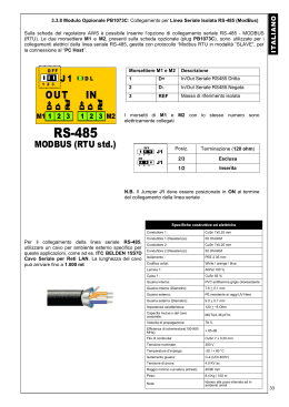
RGM300 without &
with MODBUS plug
RGM300 – Plug MODBUS RS-485 fixing procedure
1
ATTENTION!!!
2
3
Correct insertion
HELP!!!
HELP the fixing procedure
4
5
HELP!!!
6
HELP!!!
Don’t push without ATTENTION !!!
NO !!!
NO !!!
FLEXIBLE
without HELP
RGM300 – MODBUS connection plug 01.2012
FLEXIBLE
without HELP
www.selpro.it
RGM300 – Plug MODBUS RS-485 Informazioni connessione
Rt
Morsettiere M1 e M2
1
D+
2
D3
REF
120R
PC < - > RS485
2
D0+ D0-
RS-485
REF0
MODBUS (RTU std.)
PE
OFF
Rt =120R
1 2 3
OFF
Rt =120R
1 2 3
J1
PB1073_C
3
2
3
2
N°1
2
3
1
2
3
M2
M1
D0+ D0- REF
1
PB1073_C
1
120R
D0+ D0- REF
2
3
3
2
N°2
1
2
1
3
M2
M1
D0+ D0- REF
Posizione
Terminazione (120 ohm)
2/3
1/2
Linea passante
Terminale di Linea
N.B. Il Jumper J1 deve essere posizionato in ON al termine del collegamento della linea seriale
MAX
N° 32
120R
Impostazione
di fabbrica
1
Massa di riferimento isolata
J1
PB1073_C
1
120R
ON
1 2 3
J1
1
In/Out Seriale RS485 Negata
Seriale COM 0
3
Fine linea RS-485
Rt =120R
In/Out Seriale RS485 Dritta
I morsetti di M1 e M2 con lo stesso numero sono elettricamente collegati
ADATTATORE ISOLATO
1
Descrizione
D0+ D0- REF
2
3
1
2
M1
3
M2
Tutti i morsetti “D+”,“D-” e “REF” devono essere connessi con lo stesso cavo.
La schermatura del cavo và collegata a Terra ed a REF, dal solo lato “PC < - > RS485” .
•
•
•
•
D0+ D0- REF
•
END OF RS-485 LINE
•
N.B. : È assolutamente indispensabile accertarsi del corretto collegamento della linea RS485
Il cavo della linea dati (la rete Modbus), và connesso da un regolatore al successivo, partendo dall’unità Master per finire
all’ultimo dispositivo servito; NON è ammesso altro metodo di cablaggio.
I collegamenti devono essere realizzati con cavo adatto ad ambiente esterno, e non superare la lunghezza massima di 1.000 mt
Assicurarsi di NON mescolare il cavo della rete Modbus con gli altri cavi dell’impianto, soprattutto quelli a tensione di rete V~.
Gli estremi della linea (Master ed ultimo dispositivo servito) vanno terminati con una resistenza da 120ohm.
Attivare la terminazione 120ohm su adattatore RS-485 < > PC Host; sull’ultimo apparecchio della linea, posizionare J1 su ON
(2-1); su tutte le unità intermedie lasciare J1 su OFF (2-3).
Collegare a Terra il cavo che collega tutti i morsetti “REF” unicamente in prossimità della stazione Master, in modo che tutte le
stazioni si trovino allo stesso potenziale, quello del PC Host .
Collegare a Terra lo schermo del cavo in partenza dall’adattatore RS-485<>PC Host, solo in prossimità dell’adattatore stesso;
lo schermo và collegato unicamente lato PC Host, come da schema riportato in figura.
Il cavo risulterà diviso in spezzoni, uno per ogni tratta; collegare lo schermo della prima tratta solo dal lato adattatore RS-485< >
PC Host, e collegare lo schermo della seconda tratta solo dal lato Slave N°1, e così via
Per il collegamento della linea seriale RS-485, utilizzare un cavo per
ambiente esterno specifico per queste applicazioni, come ad es. :
ITC BELDEN 15S7D Cavo Seriale per Reti LAN .
RGM300 – MODBUS connection plug 01.2012
www.selpro.it
RGM300 – Plug MODBUS RS-485 CONNECTION information
Terminal block M1& M2
Rt
120R
2
D0+ D0-
OFF
Rt =120R
OFF
Rt =120R
1 2 3
PB1073_C
3
2
N°1
PB1073_C
1
120R
3
1
2
1
3
M2
M1
D0+ D0- REF
3
REF
D0+ D0- REF
2
Isolated reference mass
2
N°2
3
1
2
MAX
N° 32
120R
Factory
DEFAULT
M2
M1
D0+ D0- REF
1
3
D0+ D0- REF
2
3
1
Position
Termination 120 ohm
2/3
Inserted
1/2
Excluded
N.B. It is of utmost importance to ensure the right connection of line RS485, meaning all “D+” terminals of the network should
be connected together to the same cable, like for “D-“ and “REF”. The screening of the cable should be grounded and connected to
REF only on the “PC < - > RS485” side.
•
3
IN/Out Serial RS485 Denied
N.B. Jumper J1 should be placed as illustrated here below
J1
PB1073_C
1
120R
ON
1 2 3
J1
3
2
D-
MODBUS (RTU std.)
J1
1
2
RS-485
REF0
1 2 3
2
In/Out Serial RS485 Straight
Serial COM 0
PE
1
D+
3
END OF RS-485 LINE
Rt =120R
1
Terminals M1 and M2 are electrically connected with the same number
INSULATED ADAPTER
PC < - > RS485
1
Description
2
3
M1
M2
•
•
D0+ D0- REF
•
•
END OF RS-485 LINE
N.B. : It is of utmost importance to ensure the right connection of line RS485
•
•
The cable of the Modbus network should be laid from one device to the other, starting from the master unit and ending at the last
device served, no other cabling method is allowed.
Connections should be made with a suitable cable, do not exceed the maximum length of 1000m.
Ensure there is enough distance between the cable of the Modbus network and the other cables of the device, especially from
power voltage ones
The ends of the line (Master and last device served) should end with a 120ohm resistance: run the termination 120ohm on
adaptor RS-485< > PC Host; on the last device of the line place J1 on 2-1, on all other devices place J1 on 2-3.
Connect the cable linking the two “REF” terminals only next to the Master station so that all stations are at the same potential,
the PC Host .
Ground the screen of the cable starting from the adaptor RS-485<> PC Host only next to the adaptor itself.
(The screen must only be connected to the PC Host side, as for the diagram).
The cable will be divided into segments, one for each section, connect the screen to the first section only on the RS-485< > PC
Host adaptor side, connect the screen of the second section only on the Slave N°1 side and so on.
For the data line, use a suitable cable, i.e.:
ITC BELDEN 15S7D Serial Cable for LAN Networks.
RGM300 – MODBUS connection plug 01.2012
www.selpro.it
Scaricare