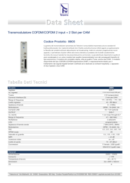
D-Matrix 8T ISTRUZIONI PER L’USO - OPERATING INSTRUCTIONS INSTRUCTIONS D’EMPLOI - BEDIENUNGSANLEITUNG Italiano 1. AVVERTENZE PER LA SICUREZZA • • L’installazione del prodotto deve essere eseguita da personale qualificato in conformità alle leggi e normative locali sulla sicurezza. Fracarro Radioindustrie di conseguenza è esonerata da qualsivoglia responsabilità civile o penale conseguente a violazioni delle norme giuridiche vigenti in materia e derivanti dall’improprio uso del prodotto da parte dell’installatore, dell’utilizzatore o di terzi. L’installazione del prodotto deve essere eseguita secondo le indicazioni d’installazione fornite, al fine di preservare l’operatore da eventuali incidenti e il prodotto da eventuali danneggiamenti. Avvertenze per l’installazione • • • • • • • Il prodotto non deve essere esposto a spruzzi d’acqua e va pertanto installato in un ambiente asciutto, all’interno di edifici. Umidità e gocce di condensa potrebbero danneggiare il prodotto. In caso di condensa, prima di utilizzare il prodotto, attendere che sia completamente asciutto. Non installare il prodotto sopra o vicino a fonti di calore o in luoghi polverosi o dove potrebbe venire a contatto con sostanze corrosive. L’eccessiva temperatura di lavoro e/o un eccessivo riscaldamento possono compromettere il funzionamento e la durata del prodotto. Maneggiare con cura. Urti impropri potrebbero danneggiare il prodotto. Lasciare spazio attorno al prodotto per garantire una ventilazione sufficiente. In caso di montaggio a muro utilizzare tasselli ad espansione adeguati allle caratteristiche del supporto di fissaggio. Messa a terra dell’impianto d’antenna • • • Il prodotto deve essere collegato all’elettrodo di terra dell’impianto d’antenna conformemente alla norma EN 60728-11. La vite predisposta per tale scopo è contrassegnata con il simbolo Si raccomanda di attenersi alle disposizioni della norma EN 60728-11 e di non collegare tale vite (morsetto) (prodotto) alla terra di protezione della rete elettrica di alimentazione. IMPORTANTE • • Non togliere mai il coperchio del prodotto, parti a tensione pericolosa possono risultare accessibili all’apertura dell’involucro. In caso di guasto non tentate di riparare il prodotto altrimenti la garanzia non sarà più valida. 2. DESCRIZIONE DEL PRODOTTO D-Matrix 8T è una centrale che permette di generare due gruppi da 1/2/4 multiplex adiacenti modulati nello standard DVB-T. Utilizza stream ricevuti da otto multiplex digitali terrestri/cavo (DVB-T, DVB-T2 o DVB-C) o letti da file transport stream .TS contenuti in una unità di memoria esterna USB. I file .TS possono essere ottenuti convertendo qualsiasi file audio/video nel formato appropriato, utilizzando un programma di conversione per PC. Il modulatore è full band, quindi è possibile modulare i mux su frequenze arbitrarie nelle bande VHF-S-UHF (114 ÷ 858 MHz). NB: Gli 8 multiplex non sono indipendenti ma legati all’interno dello stesso gruppo (MUX1-MUX2-MUX3MUX4, MUX5-MUX6-MUX7-MUX8), dai parametri del canale (o frequenza), dalla larghezza di banda e dal livello in uscita. Esempio: se viene impostato il canale in uscita del MUX 1, i canali di uscita dei MUX2-MUX3-MUX4 verranno impostati automaticamente sui canali successivi a quello selezionato. Se invece si imposta il canale in uscita del MUX4, in automatico saranno impostati i canali di uscita dei dei MUX1-MUX2-MUX3 ai canali precedenti. La stessa filosofia vale per la seconda quartina composta dai MUX5-MUX6-MUX7 e MUX8. NB: Per conoscere la configurazione dei MUX in uscita controlla il capitolo “MENU OUTPUT”. 2 Istruzioni per l’uso La programmazione può essere effettuata in due modalità • Programmazione base, tramite tastiera e display LCD presenti sul pannello frontale • Programmazione avanzata, tramite un’intuitiva interfaccia web da rete locale LAN o da remoto con il collegamento di un PC. Esempio di Installazione SIGMA 6HD LTE CAM D-MATRIX 8T CAM DTT MIX IN LAN SIGMA 6HD LTE USB Stick RF OUT PC 3 Italiano Il prodotto è dotato di: • Presa di alimentazione elettrica bipolare; • Otto ingressi digitali terrestri DVB-T / DVB-T2 / DVB-C con controllo del sovraccarico; • Otto led multicolore, due per ogni ingresso, utilizzati per indicare lo stato dell’ingresso; • Due slot common interface, ognuna associabile ad un qualsiasi ingresso oppure in modalità Flex che consente di decriptare qualsiasi programma proveniente da qualsiasi ingresso; • Ingresso MIX che consente di miscelare il segnale generato dal dispositivo con uno proveniente da un impianto di ricezione televisiva o da un altro prodotto che generi segnale RF; • Uscita RF dei multiplex generati e dai segnali provenienti dall’ingresso MIX; • Porta di rete Ethernet 10base-T / 100Base-TX; • Porta USB host per lo storage dei file .TS, l’aggiornamento firmware e il salvataggio/ripristino della configurazione; • LED multicolore per l’indicazione dello stato del sistema; • Pulsante di ripristino (interno). Italiano Gli 8 tuner (quattro gruppi da due tuner con medesimo segnale in ingresso) supportano la ricezione dei segnali digitali terrestri DVB-T/DVB-T2/DVB-C e sono in grado di fornire la telealimentazione ad un eventuale preamplificatore. Il segnale può essere fornito ad ogni gruppo di tuner in modo indipendente, utilizzando i quattro connettori superiori, oppure é possibile utilizzare la funzionalità loop-through, che consente di fornire il segnale ricevuto da uno dei gruppi a quelli successivi, in cascata. La telealimentazione é in grado di erogare una corrente massima di 200mA totale per tutti gli ingressi. Qualora questo limite venga superato, interviene un limitatore di corrente, il quale provvede a disabilitare temporaneamente la telealimentazione su tutti gli ingressi. (successivamente riabilitandoli ad uno ad uno si riesce a visualizare quale o quali provocano il guasto). In presenza di un guasto sulla telealimentazione gli ingressi vengono disabilitati, mentre la funzione loop rimane attiva (a segnalazione del guasto viene acceso il led con colore rosso corrispondente all’ingresso in sovraccarico). La ricezione dagli ingressi in errore può essere ripristinata, dopo aver risolto il guasto nell’impianto, disabilitando e riabilitando l’ingresso, oppure riavviando il D-Matrix 8T. NB: L’ingresso del primo connettore ha un filtro bassa-banda da 170 a 862 MHZ che protegge dalle interfenze che provengono dai segnali FM o GSM Il segnale ricevuto dagli ingressi può essere decriptato utilizzando un massimo di due moduli CAM, da inserire negli appositi slot situati sulla destra. Ogni slot può essere programmato in due modi: 1. Associato ad uno degli ingressi: la CAM permetterà il decriptaggio dei programmi desiderati provenienti dall’ingresso selezionato. Associando più CAM al medesimo ingresso sarà possibile il decript dei segnali con codifiche differenti. 2. Associato ad un transport stream personalizzato (FLEX): la stessa CAM permetterà il decriptaggio dei programmi provenienti anche da ingressi diversi pur appartenenti allo stesso broadcaster. Il prodotto consente di riprodurre in loop un programma salvato su file in formato standard transport stream (file .TS). Tale file può essere generato a partire da un qualsiasi file audio/video utilizzando un apposito tool di conversione. Il file deve essere presente in un dispositivo di storage USB connesso al dispositivo, formattato con filesystem FAT32. Programmi provenienti dagli ingressi o da USB possono essere rigenerati e rimodulati in modo intelligente consentendo all’installatore di scegliere il contenuto dei mux di uscita ad-hoc, a seconda del bitrate disponibile e delle preferenze dell’utilizzatore finale. Il sistema provvede alla rigenerazione automatica del transportstream, utilizzando anche alcuni parametri di posizione/priorità, in modo da poter privilegiare taluni programmi rispetto ad altri ritenuti meno importanti. Si pensi ad esempio ad un mux generato dai programmi P1, P2 e P3, ricevuti da un canale terrestre, configurati con rispettive posizioni 1,2 e 3 (a posizione inferiore corrisponde priorità superiore). Qualora il bitrate complessivo dei tre programmi sia inferiore a quello reso disponibile dalla modulazione di uscita, tutti i programmi vengono visualizzati in uscita senza alcuna perdita di bitrate. Supponiamo invece che il bitrate totale in alcuni momenti superi quello disponibile; il sistema provvederà a garantire la visione dei programmi a maggiore priorità, tagliando i programmi a priorità più bassa. Pertanto il programma P3 subirà dei degradi (squadrettamenti) mentre i programmi P1 e P2 non verranno minimamente alterati. In alcune situazioni l’installazione richiede che un transport-stream ricevuto non venga multiplexato, ma piuttosto trasmesso direttamente senza alcuna elaborazione. A questo scopo può venire abilitata la modalità denominata ALL-PID; in questa modalità ogni tipo di elaborazione sul transport-stream viene disattivata. I transport-stream in uscita vengono modulati secondo lo standard DVB-T 2K. Il dispositivo permette la gestione da remoto tramite interfaccia web. É presente un’interfaccia di rete Ethernet 10/100, che permette la connessione del dispositivo diretta con un PC (utilizzando un cavo incrociato), oppure ad una rete LAN. 4 Istruzioni per l’uso 3. INSTALLAZIONE DEL PRODOTTO All’interno dell’imballo sono contenuti i seguenti materiali: • D-Matrix 8T; • Cavo di alimentazione; • Avvertenze per la sicurezza e il manuale d’installazione del prodotto; 3.2 MONTAGGIO DEL PRODOTTO • Utilizzando gli appositi punti di fissaggio, avvitare il prodotto alla parete, in modo che sia posizionato verticalmente, per consentire una corretta dissipazione del calore; • Collegare il dispositivo alla terra dell’impianto di antenna utilizzando l’apposito morsetto; • Collegare i cavi d’antenna ai relativi ingressi; • Se necessario inserire le CAM e le relative smart-card negli appositi slot; • Se necessario inserire una unità di memoria esterna USB; • Collegare alla rete elettrica il prodotto; • Attendere l’avvio del dispositivo, quindi procedere alla configurazione; • Verificare la corretta generazione del segnale in uscita, e lo stato di ricezione degli ingressi e del sistema tramite appositi led multicolori; 3.2.1 MONTAGGIO A MURO 15cm La centrale va installata facendo riferimento alla figura sottostante, utilizzando le staffe integrate nella meccanica del prodotto. Si preveda lo spazio necessario per l’eventuale collegamento del cavo di alimentazione e la corretta ventilazione del prodotto (15cm di aria su tutti i lati). Ogni altra modalità di installazione potrebbe compromettere il corretto funzionamento del dispositivo. 15cm 15cm 15cm 5 Italiano 3.1 CONTENUTO DELL’IMBALLO Italiano 3.3 INSERIMENTO MODULI CAM Per l’inserimento dei moduli CAM negli slot, posizionare il modulo come indicato nella figura sottostante, ed esercitare una lieve pressione. Il modulo dovrebbe scorrere sulle guide senza opporre resistenza. Qualora ciò risultasse difficoltoso, verificare il corretto allineamento e il verso di inserimento. Per estrarre i moduli CAM esercitare una lieve trazione laterale, il modulo dovrebbe potersi estrarre senza difficoltà. 3.4 LED MULTICOLORE DI INDICAZIONE STATO D-MATRIX 8T è provvisto di otto led multicolore sul lato superiore (due per ogni ingresso), per l’indicazione dello stato di ricezione dei segnali in ingresso, ed un led multicolore sul lato inferiore per l’indicazione dello stato del sistema. Di seguito il significato di ogni led: COLORI LED PER STATO INGRESSI Spento: ingresso spento Arancio:ingresso attivo in attesa di aggancio Verde: ingresso attivo e agganciato Rosso: ingresso in sovra-assorbimento COLORI LED PER STATO SISTEMA (durante l’inizializzazione) Arancio:boot sistema Rosso: avvio applicazioni Verde: sistema avviato senza errori COLORI LED PER STATO SISTEMA (sistema avviato) Verde: situazione normale Arancio:anomalia Rosso lampeggiante: fase di aggiornamento e/o recovery 6 Istruzioni per l’uso 4. ISTRUZIONI PER L’UTILIZZO In alternativa alla configurazione da pannello è possibile utilizzare un PC per accedere alla programmazione tramite la semplificata interfaccia web (vedere paragrafo 5.2 PROGRAMMAZIONE TRAMITE INTERFACCIA WEB). In caso di necessità è possibile riportare il prodotto ai parametri di fabbrica. ATTENZIONE: in questa condizione la lingua di default è l’inglese. Dopo il ripristino di fabbrica sarà necessario riprogrammare il D-MATRIX 8T in quanto i parametri preimpostati potrebbero non coincidere con quelli voluti. 5.ISTRUZIONI PER LA PROGRAMMAZIONE 5.1 PROGRAMMAZIONE BASE DA PANNELLO D-MATRIX 8T è programmabile tramite tastiera e display integrati dal pannello frontale. Per accedere al menù di programmazione premere il tasto √, inserire il codice utente (di default è 1234) e confermare premendo nuovamente il tasto √. Muoversi nel menù utilizzando i tasti freccia-su e freccia-giù per selezionare il parametro desiderato, quindi premere il tasto √ per confermare ed accedere. Per uscire dalla selezione utilizzare il tasto X. Durante la visualizzazione di un parametro utilizzare i tasti freccia-sinistra e freccia-destra per selezionare/ cambiare il valore, quindi premere X per uscire (non è necessario confermare). Se è necessario inserire un valore numerico, invece, utilizzare il tastierino 0-9 per inserire il valore, quindi confermare premendo il tasto √. NB: L’interfaccia di configurazione ha un timeout di 5 minuti; trascorso tale tempo senza che venga effettuata una ulteriore modifica alla programmazione o un salvataggio, viene ripristinata l’ultima configurazione salvata del prodotto o la configurazione di fabbrica. Il menù é disponibile in diverse lingue. Per cambiare la lingua del menu accedere al menu principale “LINGUA” e selezionare la lingua desiderata confermando con il tasto √. FUNZIONI TASTIERINO NUMERICO • • • • • Freccia-sù/freccia-giù: si usano per navigare tra le varie voci di menu; Freccia-sx/freccia-dx: si usano per selezionare il valore di un parametro; Tasto √: si usa per confermare un valore inserito o entrare in un menù o sottomenù; Tasto X: si usa per cancellare un valore inserito o uscire da un menù o sottomenù; Tasto S: si usa per salvare le modifiche effettuate; 7 Italiano • Attendere l’inizializzazione del D-MATRIX 8T (a display compare la scritta D-MATRIX FRACARRO); • Accedere al menù del pannello premendo il pulsante √, digitando il codice utente (default 1234) e confermando con √; • Eseguire le operazioni di programmazione come indicato nei paragrafi successivi (vedere paragrafo 5.1 PROGRAMMAZIONE BASE DA PANNELLO); • Verificare che il segnale sia disponibile all’uscita, utilizzando un misuratore di campo; • Collegare al connettore d’uscita il cavo della distribuzione. Italiano -INPUT MENU: permette di selezionare l’ingresso da programmare tra i 9 disponibili (vedi flow chart INPUT). FLOW CHART INPUT -INPUT 1, INPUT 2, INPUT 3, INPUT 4, INPUT 5, INPUT 6, INPUT 7 e INPUT8 ASSOCIA A: Gli 8 tuner sono organizzati in quattro gruppi di due; ogni gruppo può ricevere il segnale proveniente dal connettore di ingresso oppure tramite LOOP dal gruppo precedente. (per gli INPUT 1 e 2 non sarà possibile la seconda opzione in quanto il segnale deve provenire obbligatoriamente dal CONNETTORE d’ingresso). NB: utilizzando l’impostazione LOOP è possibile utilizzare come fonte del segnale un solo ingresso (il primo) per i tuner successivi. Ad esempio, se si vuole utilizzare solo il connettore di ingresso INPUT1/2 e si seleziona LOOP su tutti gli altri input, i medesimi riceveranno il segnale dall’INPUT 1/2. In questo caso l’unico segnale disponibile sarà quello sull’INPUT 1/2 e in caso di anomalie in ricezione (segnale instabile e/o che sgancia) potrebbero verificarsi delle problematiche di ricezione anche sugli INPUT collegati in LOOP; in questo caso per risolvere sarà sufficiente disabilitare l’opzione LOOP e portare il segnale sugli altri connettori in ingresso. ABILITA: permette di decidere se utilizzare o meno il ricevitore collegato all’ingresso selezionato; impostando OFF il ricevitore verrà spento. TELEALIMENTAZIONE: Consente di abilitare (ON) o disabilitare (OFF) la telealimentazione sull’ingresso per alimentare un amplificatore collegato a monte della centrale. STANDARD: seleziona lo standard di modulazione del canale che si desidera agganciare: DVB-T o DVB-C. TUNER DVB-T: permette di impostare i parametri di ricezione di un segnale DVB-T. IMPOSTA FREQ: Larghezza di banda: imposta la larghezza di banda del canale in ingresso 7 o 8 MHz. Frequenza (MHz): imposta la frequenza del canale in ingresso. SELEZIONA PER CANALE: Paese: modifica del paese (Europa, Francia, UK ed Australia). Canale ingresso: imposta il canale d’ingresso che si vuole ricevere. Offset: imposta la correzione in frequenza del canale in ingresso; HI/LO PRIORITY: permette di impostare la priorità del canale (High e Low); TUNER DVB-C: permette di impostare i parametri di ricezione di un segnale DVB-C IMPOSTA FREQUENZA (MHz): imposta la frequenza in MHz del canale in ingresso. SELEZIONA PER CANALE: Paese: modifica del paese (Europa, Francia, UK ed Australia) 8 Istruzioni per l’uso Italiano Canale ingresso: imposta il canale d’ingresso che si vuole ricevere. Offset: imposta la correzzione in frequenza del canale in ingresso; COSTELLAZIONE: Consente di impostare la costellazione relativa al canale in ingresso: Auto, 16QAM, 32QAM, 64 QAM, 128 QAM e 256QAM SYMBOL RATE: Permette di impostare il symbol rate del canale in ingresso [1000-6999 KSps]; MISURE: contiene le informazioni riguardanti il multiplex ricevuto dall’ingresso selezionato; LOCK: permette di verificare se il ricevitore ha AGGANCIATO il segnale (Lock) oppure no (not Locked); NETWORK NAME: visualizza il nome del canale (è un parametro non modificabile). LIVELLO RF (dBµV): visualizza il livello del segnale in ingresso (dbuV); CBER: permette di visualizzare il BER (qualità) del segnale in ingresso; MER (dB): permette di visualizzare il MER del segnale in ingresso. DVB info: Standard: indica lo standard del multiplex in ingresso (DVB-T oppure DVB-C) Modulation: indica il tipo di modulazione del multiplexer in ingresso (es. 64QAM) Hierarchy: indica la gerarchia del mux, con alta priorità (HP) o bassa priorità (LP) Code Rate: indica il FEC del canale agganciato, potrà assumere i valori ½, 2/3, 3/4, 5/6 e 7/8 nel caso di un canale DVB-T inoltre anche 3/5 e 4/5 nel caso di DVB-T2 Guard interval: indica l’intervallo di guardia del canale agganciato, potrà assumere i valori 1/4, 1/8, 1/16 ed 1/32 nel caso di un canale DVB-T inoltre anche 1/128, 19/128 e 19/256 nel caso di DVB-T2 Mode: riporta il numero di portanti del canale agganciato ed assumerà valori di 8k o 2k per i canali in DVB-T, inoltre 1K, 4K, 16k e 32K per i canali DVB-T2 -INPUT USB: permette di gestire l’ingresso USB come fonte di un segnale audio/video in formato transport stream impostando il suo sottomenù. ABILITA: consente di attivare o meno la lettura dei file audio/video presenti su un’unità di memoria esterna USB; SELEZIONE FILE: permette di selezionare quale file si desidera utilizzare tra quelli presenti sull’unità di memoria esterna USB; STATO USB: mostra lo stato del file selezionato. NB: D-MATRIX 8T riconosce e riproduce solo file audio/video in formato TS; qualunque altro formato audio/ video andrà convertito nel formato corretto tramite dei software reperibili in rete. -MENU’ COMMON INTERFACE: consente di impostare i parametri relative alle CAM presenti FLOW CHART COMMON INTERFACE CAM 1 / CAM 2: selezionare la CAM da configurare: NOME MODULO: permette di verificare il nome del modulo common interface inserito nell’apposita slot; ASSOCIA A: permette di associare la CAM scelta ad uno degli 8 INPUT disponibili o impostare il suo funzionamento in modalità FLEX (vedi paragrafo successivo); PROGRAMMI: permette di aggiungere e/o rimuovere i programmi da decriptare; RESET CAM: consente di resettare la CAM selezionata. -MODALITÀ FLEX CAM: La modalità FLEX permette di non associare solamente la CAM scelta a un ingresso specifico, bensì di decriptare dei programmi provenienti da qualsiasi ingresso della centrale. Impostando la voce “ASSOCIA A” come “FLEX” si otterrà in “PROGRAMMI” la lista di tutti i programmi provenienti dagli 8 INPUT e sarà quindi possibile decriptare i programmi desiderati, indipendentemente dall’input di provenienza. 9 Italiano -MENU’ OUTPUT: consente di configurare il segnale in uscita dal D-MATRIX 8T per la distribuzione. FLOW CHART OUTPUT MODO -Standard del segnale in uscita: lo standard del segnale in uscita è DVB-T (2K). -MUX 1, MUX 2, MUX 3, MUX 4, MUX5, MUX6, MUX7 e MUX8: permette di scegliere quale MUX di uscita configurare, impostando i vari sottomenù. CONFIGURAZIONE: permette di impostare tutti i parametri dei MUX in uscita. MODO: consente di abilitare il MUX scelto; impostando in OFF il MUX viene spento. I multiplex in uscita sono ragruppati in 2 gruppi da 4 multiplex (QUAD) e possono abilitati e disabilitati in questo modo: interamente (tutti i mux, QUAD), per metà (MUX 1 e MUX2, TWIN) o per un quarto (solo MUX1, SINGLE). La stessa modalità vale per il secondo quartetto composto dal MUX5, MUX6, MUX7 e MUX8. CANALE DI USCITA: CANALE DI USCITA: permette di impostare il canale di uscita in cui verrà rimodulato il MUX; questo parametro modifica automaticamente anche il valore del canale dei MUX adiacenti, nella stessa quartina. Esempio se rimodulo il MUX 1 nel canale E21, i MUX 2, 3 e 4 saranno rimodulati rispettivamente nei canali E22, E23 e E24. PAESE: permette di scegliere la canalizzazione impostando il Paese di installazione FREQ. USCITA: FREQUENZA (MHz): permette di impostare la frequenza di uscita in cui verrà rimodulato il MUX; questo parametro modifica automaticamente anche il valore della frequenza dei Multiplex nello stesso gruppo. LARGH. DI BANDA: permette di scegliere la larghezza della banda, tra le varie possibilità c’è: 7 MHz, 8 MHz e 6MHz; questo parametro modifica automaticamente anche il valore della larghezza di banda dei MUX adiacenti, nello stesso gruppo. FEC: permette di impostare il parametro relativo al FEC (Forward Error Connection) tra le varie possibilità (1/2, 2/3, ¾, 5/6, 7/8). INT. DI GUARDIA: permette di impostare l’intervallo di guardia tra le varie possibilità (1/4, 1/8, 1/16, 1/32). NUM. PORTANTI: Visualizza il numero di portanti del segnale DVB-T in uscita (solo 2K). COSTELLAZIONE: permete di impostare la costellazione con cui vengono modulate le portanti 16QAM e 64QAM. 10 Istruzioni per l’uso 11 Italiano LIVELLO RF: permette di regolare il livello di uscita in dBuV, a passi di 1 dBuV; questo parametro modifica automaticamente anche il valore del livello dei MUX adiacenti, nella stessa quartina. SPETTRO: permette di impostare lo spettro come NORMALE o INVERTITO in base allo strumento di ricezione che potrebbe funzionare solamente con una delle due modalità; di norma si utilizza l’impostazione NORMALE. BITRATE: permette di conoscere le misurazioni effettuate sul bitrate del multiplex dei programmi in uscita; BITRATE USATO: fornisce un’indicazione del bitrate utilizzato. Questo parametro si riferisce alla misura totale su tutti i programmi aggiunti alla lista di programmi in uscita BITRATE DISP.: fornisce un’indicazione del bitrate disponibile. Questo parametro si riferisce alla misura totale di bitrate disponibile in uscita dopo l’inserimento di uno o più programmi PICCO BR. USATO: fornisce una misura in bit/s del picco di bitrate massimo utilizzato dai programmi presenti nel MUX di uscita PICCO BR DISP.: fornisce una misura in bit/s del picco di bitrate totale disponibile nel MUX di uscita RESET PICCHI BR: permette di resettare i picchi ai valori iniziali calcolati in base alle impostazioni di modulazione COFDM. In seguito ad un Overflow di bitrate, dopo il quale i picchi hanno raggiunto il loro valore limite, è necessario utilizzare questa funzione. ALLARME OVERFLOW: permette la gestione degli allarmi di Overflow di bitrate STATO ALLARME: indica se si è verificato un overflow di bitrate ANNULLA ALLARME: consente di annullare l’allarme di overflow. Eseguendo questa funzione si riporta il prodotto alle condizioni di funzionamento standard (spegnimento del LED rosso) ABILITA: permette di abilitare (impostando il parametro ON) la funzione di segnalazione allarme di overflow; impostando il valore su OFF l’opzione è disabilitata. Italiano -MENU’ PROGRAMMI: è possibile selezionare i programmi che verranno trasmessi nei MUX precedentemente creati e monitorare la banda occupata in trasmissione. FLOW CHART PROGRAMMI MUX 1, MUX 2 , MUX 3, MUX 4, MUX5, MUX6, MUX7 e MUX8: consente di selezionare il MUX che si vuole modificare. •ALL PIDS: consente di trasmettere sul multiplex in uscita tutti i pid associati agli ingressi o alle CAM. •ORDINA LISTA: permette di impostare il criterio di ordinamento della lista programmi. la lista può essere ordinata per: INGRESSO: l’ordinamento avviene per il numero dell’ingresso LCN: l’ordinamento avviene per LCN cioè a seconda del numero associato al programma indistintamente dall’ingresso di provenienza. PRIORITÀ: l’ordinamento avviene per la priorità associata al programma •LISTA PROGRAMMI: permette di impostare la lista dei canali in uscita. AGGIUNGI: permette di aggiungere il programma selezionato alla lista dei programmi da distribuire in uscita. Una volta aggiunto, il programma viene contrassegnato con la lettera A nella lista dei canali. TOGLI: permette di cancellare il programma selezionato dalla lista dei programmi da distribuire in uscita. POSIZIONE: permette di impostare la priorità e di conseguenza la posizione del programma all’interno della lista dei programmi. LCN: permette di impostare l’LCN del programma, I valori selezionabili sono compresi tra 0 e 999. Al valore 1000 corrisponde LCN disabilitato. BANDA: consente il monitoraggio del bitrate del programma attraverso i seguenti parametri. MONITORA: permette di abilitare/disabilitare il monitoraggio del bitrate del programma selezionato, permette di verificare, in base al bitrate del programma se può essere contenuto nel multiplex. VALORE MEDIO: permette di visualizzare il valore medio del bitrate del programma VALORE DI PICCO: permette di visualizzare il valore di picco del bitrate del programma PROP. DEL PROGRAMMA: permette di visualizzare alcune informazioni utili sui programmi NOME PROGRAMMA: permette di visualizzare il nome del programma NOME PROVIDER: permette di visualizzare il nome del provider INGRESSO: permette di visualizzare l’ingresso di provenienza corrispondente TIPO DI PROGRAMMA: permette di visualizzare il tipo di programma (TV, RADIO,…). SERVICE ID: permette di visualizzare il service ID del programma. •CONF. AVANZATA SEL. PAESE: permette di selezionare il paese d’installazione TSID: permette di visualizzare e modificare l’ID associato al transport stream dal broadcaster. 12 Istruzioni per l’uso -MENU’ SETUP SISTEMA: consente di impostare i parametri relativi al funzionamento del sistema. - SETUP SISTEMA RETE: permette la configurazione della rete configurando i seguenti paramentri: ABILITA DHCP: consente di abilitare la gestione automatica dell’assegnazione dei parametri di rete, qualora nella sottorete sia presente un server DHCP. L’opzione di default è disabilitata. NB: NON abilitare la funzione DHCP qualora siano stati impostati i parametri della rete riportati di seguito. IP: assegna l’indirizzo IP della centrale, l’indirizzo deve essere univoco e compatibile con quello rilevato dalle impostazioni della rete LAN a cui si vuole collegare il D-MATRIX 8T (default 192.168.0.2) NETMASK: assegnare la sotto maschera di rete. Utilizzare un netmask compatibile con la propria sottorete (default 255.255.255.0) GATEWAY: configura l’indirizzo gateway della propria sottorete (default 192.168.0.1) DNS: consente l’impostazione del server DNS, se disponibile (default 0.0.0.0) WEB SERVER PORT: consente di modificare la porta di comunicazione con la rete Ethernet (default 80) MAC ADDRESS: consente di visualizzare l’indirizzo che identifica in modo univoco il dispositivo. ATTENZIONE: DOPO UN RESET DI DEFAULT DEL PRODOTTO I VALORI DI TALI PARAMETRI RITORNANO QUELLI DELLE IMPOSTAZIONI DI FABBRICA. LINGUA: permette di impostare la lingua di visualizzazione dei menù della centrale (ITALIANO, TEDESCO, FRANCESE ed INGLESE). RESET: consente di riavviare la centrale SALVA CONFIG.: permette di copiare la configurazione del prodotto su una pen drive USB nel formato .XML. Inserire la pen drive nella porta USB del prodotto prima di salvare la configurazione. CARICA CONFIG.: permette di caricare la configurazione del prodotto da un file in formato XML precedentemente salvato su una pen drive. CONTRASTO LCD: consente di regolare il contrasto del display LCD per una migliore visione. CAMBIA PIN: permette di cambiare il codice PIN del D-MATRIX 8T per accedere alla programmazione (default 1234) CONFIG. DI FABBR.: consente di riportare il D-MATRIX 8T alle impostazioni di fabbrica, cancellando così tutte le impostazioni apportate dall’utente. AGGIORNA SW: permette di aggiornare il software del sistema utilizzando un pacchetto di upgrade salvato precedentemente in una periferica di memorizzazione USB. VERS. SOFTWARE: visualizza la versione software del D-MATRIX 8T ESITO SW UPDATE: visualizza l’esito dell’aggiornamento software INIZIO SW UPDATE: consente di eseguire l’aggiornamento software prelevando il pachetto di upgrade dalla memoria USB inserita. 13 Italiano FLOW CHART SISTEMA Italiano 5.2 PROGRAMMAZIONE TRAMITE INTERFACCIA WEB È possibile configurare il dispositivo tramite l’interfaccia web. Dopo aver configurato i parametri di rete tramite il pannello frontale ed aver connesso il dispositivo ad una rete locale, o ad un PC tramite cavo incrociato, è possibile operare tramite browser web. ESEMPIO DI CONFIGURAZIONE DIRETTA CON PC Modificare innanzitutto l’indirizzo IP, impostandone uno appartenente alla stessa sottorete e assegnato nelle proprietà della scheda di rete locale LAN del PC. Parametri impostati nelle proprietà della scheda di rete del PC: • IP: 192.168.0.3 • SUBNET MASK: 255.255.255.0 • GATEWAY: 192.168.0.1 Parametri da modificare nelle impostazioni di rete del D-MATRIX 8T: • IP: 192.168.0.2 (deve essere univoco nella propria rete) • SUBNET MASK: 255.255.255.0 • GATEWAY: 192.168.0.1 Collegare il dispositivo al PC con un cavo cross UTP di CAT-5E o superiore. Avviare un browser internet (si consiglia di utilizzare Google Chrome o Mozilla Firefox) e digitare nella barra degli indirizzi l’indirizzo IP associato alla D-MATRIX 8T (nell’esempio sarà 192.168.0.2); verrà visualizzata la schermata iniziale di figura 1 in cui vengono richiesti i dati di accesso: digitare quindi il nome utente e la password per l’accesso, che di default sono: - NOME UTENTE: admin - PASSWORD: 1234 FIG. 1 14 Istruzioni per l’uso Confermando con OK o accedi apparirà la seguente schermata (fig. 2) Italiano FIG.2 Selezionare la lingua cliccando sulla bandiera relativa in alto a destra (inglese, italiano, francese e tedesco). NOTA: la configurazione deve essere effettuata utilizzando una sola finestra del browser così da non incorrere in errate configurazioni; non è possibile quindi aprire due o più schede di configurazione perchè la sola che rimarrà funzionante sarà sempre e solamente l’ultima aperta. IMPORTANTE: per poter accedere alla programmazione tramite web interface è necessario che il menù da pannello non sia in uso. L’interfaccia web potrebbe subire variazioni in funzione della versione software installata nel prodotto. Nella homepage di figura 2 viene visualizzato lo stato generale del sistema D-MATRIX 8T. La voce STATO consente di verificare in qualsiasi momento la versione software installata sul prodotto ed il relativo serial number. La sezione INGRESSO rappresenta lo stato degli ingressi, visualizzando i dati principali relativi ai parametri di livello e qualità di ricezione (CBER e MER), oltre al nome e il numero di canale ricevuto. Per ogni ingresso è presente una spia di indicazione dello stato dell’ingresso, che ha le seguenti segnalazioni: • VERDE se l’ingresso è abilitato ed il ricevitore è agganciato (per USB: funzionalità abilitata e file letto correttamente); • GIALLO se l’ingresso è abilitato ma il ricevitore non è agganciato (per USB: funzionalità abilitata ma file mancante, non selezionato o non compatibile); • ROSSO se l’ingresso è in sovraccarico (telealimentazione); • GRIGIO se l’ingresso non è abilitato. La sezione USCITA rappresenta lo stato degli otto MUX di uscita, visualizzando il canale e la frequenza di uscita, il livello RF, il bitrate utilizzato complessivamente dai programmi inseriti e quello ancora disponibile per il MUX. Questa informazione si ha sia in formato numerico che in formato grafico grazie alla barra orizzontale: la parte di colore VERDE indica il bitrate istantaneo utilizzato, la parte GRIGIA indica il picco massimo e quella BIANCA indica il bitrate ancora disponibile. È inoltre disponibile il pulsante RESET PICCO per resettare l’indicazione del picco e dell’evento di overflow. Per ogni MUX di uscita è inoltre presente una spia di indicazione dello stato, che assume i seguenti colori: • VERDE se il MUX è nella condizione di normale funzionamento; • VERDE SCURO se il MUX è attivo, ma la monitoria di overflow è disabilitata; • GRIGIO se il MUX è spento; • ROSSO se il MUX ha registrato un evento di bitrate overflow NB: è possibile visualizzare tutta la sezione ingresso e uscita attraverso i tasti prev e next oppure trascinando con il mouse a destra e sinistra la schermata. 15 Italiano 5.2.1 CONFIGURAZIONE INGRESSI DTT Cliccando con il mouse su uno degli 8 ingressi oppure utilizzando il menù in alto CONFIGURAZIONE -> INGRESSO -> INPUT 1 / INPUT 2 / INPUT 3 / INPUT 4 / INPUT 5 / INPUT 6 / INPUT 7 e INPUT8 si accede alla seguente schermata: FIG. 3 Nella finestra sono presenti tutti i parametri relativi all’ingresso selezionato, ovvero: • Checkbox per l’abilitazione del ricevitore. Si consiglia di disabilitare gli ingressi non utilizzati in modo da consentire un maggior risparmio energetico; • Associazione del ricevitore alla sorgente del segnale, ovvero al CONNETTORE o in LOOP (prelevando quindi il segnale a cascata dall’ingresso precedente); • Selezione della modalità di inserimento della frequenza di ingresso (per canale o per frequenza MHz); • Inserimento della larghezza di banda e della frequenza MHz (se la selezione dell’ingresso avviene per frequenza); • Inserimento del paese, del numero del canale e dell’offset (se la selezione dell’ingresso avviene per canale); • Selezione dello standard RF della frequenza in ingresso; • Scelta della priorità del canale in ingresso; • Pulsante SALVA, per il salvataggio delle impostazioni. Nel riquadro destro sono invece visualizzate le informazioni dettagliate del relative allo stato di aggancio del multiplex, alla potenza/qualità del segnale e a tutte le informazioni riguardo al canale agganciato. PER RENDERE EFFETTIVE LE MODIFICHE, SALVARE LA CONFIGURAZIONE. 16 Istruzioni per l’uso 5.2.2 CONFIGURAZIONE INPUT USB Spuntare la casella ABILITAZIONE per abilitare la lettura della chiave USB. Selezionare il file desiderato da SELEZIONA FILE; salvare infine la configurazione premendo sul pulsante SALVA. Se il file non é mai stato utilizzato, il sistema provvederà ad analizzare il formato e il bitrate per effettuare una configurazione automatica; successivamente il sistema crea e salva nell’USB un file con stesso nome ma estensione .FR per rendere più fluido un futuro utilizzo. Nella sezione a destra la spia di indicazione lock deve accendersi di verde per segnalare che la lettura del file sta avvenendo con successo. Le informazioni relative al transport in esecuzione appariranno nei campi in basso a destra. Durante la pre-analisi che richiede alcuni minuti lo stato dell’USB viene indicato “In caricamento”. Quando un file viene riprodotto e si presenta lo stato “File OK” con spia di indicazione verde; alla lista dei programmi in ingresso verranno aggiunti i programmi contenuti nel file selezionato; questi ultimi potranno essere aggiunti alle liste dei programmi in uscita. 17 Italiano Il prodotto consente di distribuire un transport-stream dell’utente da file .TS; i programmi contenuti nel file specificato verranno inseriti nella lista dei programmi e potranno essere distribuiti nei MUX di uscita, assieme a programmi ricevuti da satellite. Il file .TS può essere creato, a partire da un file audio/video generico, utilizzando appositi tool di conversione scaricabili da internet. Il file per essere riprodotto deve essere salvato in una periferica di memorizzazione USB (chiavetta flash o hard-disk) formattata nel filesystem FAT32. Per usufruire della funzionalità USB basta collegare il dispositivo di storage USB al D-MATRIX 8T e accedere alla schermata di configurazione dalla homepage cliccando su USB oppure tramite il menù CONFIGURAZIONE -> INGRESSO -> USB; la pagina di configurazione che si aprirà sarà la seguente Fig.4 Italiano 5.2.3 CONFIGURAZIONE COMMON INTERFACE Tramite il menù CONFIGURAZIONE -> COMMON INTERFACE -> CAM 1 / CAM 2 è possibile accedere alla pagina di configurazione dei moduli CAM, inseriti nei rispettivi slot; la nuova pagina si presenterà come la figura sottostante: Fig. 5 Nella schermata è possibile visualizzare il nome della CAM inserita nello slot selezionato; nel caso non fosse presente, o non venisse inizializzata correttamente, lo stato della cam è “NO MODULE”. Il campo ASSOCIA A permette di impostare la modalità di funzionamento dello slot CAM selezionato: • Associato all’ingresso INPUT1 / INPUT2 / INPUT3 / INPUT4 / INPUT5 / INPUT6 / INPUT7 / INPUT8, la cam sarà associata esclusivamente all’ingresso selezionato e potrà decriptare solo i programmi in ricezione da quel canale; • Associato alla modalità FLEX, la cam potrà decriptare qualsiasi programma proveniente da qualsiasi degli 8 ingressi. Per ognuno dei programmi ricevuti sarà possibile verificare da quale ingresso proviene (colonna “ingresso”); l’icona nella colonna “in chiaro” indica se il programma è free to air o criptato: per abilitare il programma alla decriptazione sarà sufficiente spuntare il relativo box nella colonna “decrypt”. È possibile accedere alle funzioni avanzate della CAM, cliccando sui relativi pulsanti: • RESET CAM: Reset/riavvio del modulo CAM inserito nello slot; • MENU COMMON INTERFACE: consente l’accesso al menù della common interface (la funzione è abilitata solo se la CAM supporta tale funzione)(vedi fig. 6); • MOSTRA MESSAGGI CAM: mostra gli eventuali messaggi della CAM (abilitato solo se ci sono messaggi precedenti); • IMPOSTAZIONI AVANZATE: permette di modificare le impostazioni avanzate del modulo CAM (vedi fig. 7) 18 Istruzioni per l’uso Italiano Fig. 6 Fig. 7 La figura 6 mostra la finestra del “MENU COMMON INTERFACE” associato alla cam: la pagina consente di visualizzare le informazioni sul modulo CAM, sulla Smart Card e di scaricare l’ultima versione della CAM inserita. La figura 7 mostra la finestra delle “IMPOSTAZIONI AVANZATE” della cam: la pagina consente di modificare le impostazioni avanzate del modulo CAM inserito. Le voci “CAPMT Management” e “CAPMT Sending” si riferiscono alla gestione del decrypt della CAM; è possibile scegliere le varie modalità dal menu a tendina. “CAPMT Resize”, se abilitata, permette il decript solo della parte audio e video del programma (in questo caso il numero di programmi decriptati potrebbe essere maggiore), mentre se disabilitato si decripta tutto il contenuto: audio, video, ttx, sottotitoli, MHP ecc. “CAPMT Resend Attemps” permette di impostare il numero di tentativi di decriptaggio di un programma che la CAM esegue prima di eseguire un autoriavvio; di default questo valore è impostato a 3. Le voci “TS Framing” e “TS Clock” permettono di specificare rispettivamente di inviare i dati via transport stream con pacchetti da 188 o 204 bytes e quale bitrate utilizzare (modificare solamente dopo aver consultato le specifiche tecniche della CAM, un’impostazione scorretta potrebbe compromettere il corretto funzionamento della stessa; i parametri impostati di default sono adatti alla maggior parte della CAM in commercio). La funzione “Riferimento Temporale” consente la sincronizzazione della CAM con le informazioni contenute nei programmi in ingresso: lasciando l’impostazione in AUTO la CAM esegue in automatico la ricerca nei vari INPUT. Per rendere le modifiche effettive sarà necessario cliccare su APPLICA e successivamente su OK. 19 Italiano 5.2.4 CONFIGURAZIONE MUX DI USCITA Tramite il menù “CONFIGURAZIONE USCITA” cliccando sul menù CONFIGURAZIONE -> USCITA -> MUX 1 / MUX 2 / MUX 3 / MUX 4 / MUX 5 / MUX 6 / MUX 7 / MUX 8 è possibile accedere alla pagina di configurazione dei Multiplex in uscita rimodulati secondo lo standard DVB-T. Fig. 8 All’inizio della finestra si specifica lo standard di modulazione utilizzato (DVB-T non modificabile). La frequenza del multiplex in uscita può essere modificata: per frequenza (MHz), inserendo la frequenza e la larghezza di banda, oppure per canale, inserendo il numero di canale secondo le canalizzazioni standard previste per i vari paesi. La modalità del mux in uscita permette di abilitare (singolarmente, in modalità TWIN a due o in modalità QUAD in quattro il mux in uscita). NB: I mux in uscita non sono indipendenti ma legati all’interno nello stesso gruppo dai seguenti parametri: frequenza di uscita, larghezza di banda e il livello d’uscita. Quindi, nel momento in cui si vanno a modificare questi parametri in un multiplex, immediatamente verrà modificata anche l’impostazione per i multiplex dello stesso gruppo. I 2 gruppi sono così divisi: MUX1-MUX2-MUX3-MUX4 e MUX5-MUX6-MUX7-MUX8. Livello RF permette di impostare la potenza di uscita in dBuV, nel range previsto dalla specifica tecnica (75 - 95 dbuV). Seguono alcuni parametri che riguardano lo standard di modulazione DVB-T: FEC (1/2 ,2/3, 3/4, 5/6, 7/8), intervallo di guardia (1/4,1/8,1/16,1/32), costellazione(QPSK,16QAM e 64QAM), numero di portanti (8K, 2K), spettro (normale o invertito). Il box “Allarme overflow” indica se una situazione di overflow di banda debba essere notifica all’utente dal led posto sul lato inferiore o meno. NB:Per rendere effettive le modifiche è necessario cliccare sul pulsante “Salva”. 20 Istruzioni per l’uso 5.2.5 CONFIGURAZIONE PROGRAMMI Fig. 9 Nella sezione a sinistra viene visualizzata la lista dei programmi: ricevuti dagli ingressi, decriptati dalle CAM e immessi nel sistema tramite file .TS su periferica di storage USB. La casella di inserimento testo e i menu a tendina in testa alla tabella consentono di filtrare la lista programmi per una ricerca più facile. La modalità semplice nasconde automaticamente i programmi duplicati in caso di decrypt su CAM: se un programma proveniente da un ingresso viene aggiunto in decrypt, verrà mostrata solamente la versione decriptata; i programmi non aggiunti in decrypt verranno invece sempre visualizzati. La modalità avanzata mostra invece tutti i programmi, indipendentemente dal fatto che questi vengano decriptati su CAM o meno. Le colonne della tabella dei programmi in ingresso indicano rispettivamente: il nome del programma, l’ingresso di appartenenza, il tipo di programma (TV, Radio, Dati), se la ricezione è in chiaro o criptato, se è attiva la decriptazione da parte di una delle due CAM e la banda utilizzata dal programma (se il relativo box é abilitato). Se il programma viene utilizzato per creare uno dei otto MUX in uscita, viene automaticamente flaggata la casella e visualizzata la banda relativa. Per aggiungere dei programmi ad una uscita trascinare il nome del programma dalla lista di ingresso a quella di un’uscita desiderata, con un’operazione di drag-and-drop (prendi e trascina). Per far ciò, basta cliccare e mantenere premuto con il tasto sinistro del mouse sopra al programma desiderato e spostarlo all’interno della tabella relativa all’uscita del MUX. Le colonne della tabella USCITA di figura 9 indicano: il nome del programma, l’ingresso da cui proviene, la posizione del programma (una posizione di numero inferiore ha una priorità più alta), il valore LCN assegnato (0 se non specificato), il valore LCN HD assegnato (0 se non specificato), la banda utilizzata. La posizione (o priorità) determina l’importanza dei programmi e quindi anche quale verrà tagliato per primo in caso di bitrate overflow, ad esempio posizione 1 = priorità più alta, quindi programma più importante e quello più salvaguardato (cfr Paragrafo Indicazioni per la programmazione). Il parametri LCN e LCN HD devono essere impostati in modo che ogni programma generato in uscita, anche tra più dispositivi, abbia un valore distinto. Nel caso non si intenda specificarli, inserire il valore 0. Per rimuovere un programma da una lista di uscita cliccare sul simbolo X nella colonna più a destra (AZIONI) 21 Italiano Tramite il menù CONFIGURAZIONE -> PROGRAMMI -> MUX 1 / MUX 2 / MUX 3 / MUX 4 / MUX 5 / MUX 6 / MUX 7 / MUX 8 è possibile accedere alla pagina di configurazione dei Multiplex in uscita; ne verranno visualizzati i parametri relativi, come di seguito: Italiano Nella parte inferiore della tabella è riportata la banda stimata di utilizzo dei programmi (somma dei programmi non considerando tabelle relative al TS e PID in comune) in uscita e l’indicazione dell’intervallo di programmi visualizzati in totale. Cliccando sull’icona <proprietà> nella colonna più a destra, é possibile accedere ad una gestione avanzata del programma. Cliccando sul pulsante <proprietà del programma> viene visualizzata la seguente schermata: Fig. 10 Nella prima tabella si possono modificare, scrivendo direttamente sull’apposito spazio i parametri del programma come: il nome, il provider, il SID, il PID della PMT. Una volta modificato il parametro può essere ripristinato (rimesso l’originale riportato nella seconda colonna) semplicemente cliccando sulla freccia sulla destra. L’ultimo parametro della lista permette attraverso un menu a tendina di scegliere come impostare il programma affinché venga dichiarato come Free to air o criptato dal decoder: • sempre in automatico: se il programma è decriptato dalla cam, viene dichiarato free to air automaticamente • sempre si: il programma viene sempre dichiarato free to air anche se non viene decriptato dalla cam; • sempre no: il programma viene sempre dichiarato criptato anche se viene decriptato dalla cam; • non modificato: il programma viene dichiarato free to air se non viene modificato ovvero se non viene inviato alla cam per la decodifica. La seconda tabella riguarda invece la gestione della lista PID. È infatti possibile cambiare scrivendolo nell’apposito spazio i seguenti PID: PCR video stream, audio stream, teletext, MHP, application information table. Nell’ultima colonna di questa tabella cliccando sull’apposito simbolo, si possono svolgere alcune azioni su ciascun PID del programma: elimina il PID (la riga del PID eliminato viene evidenziata in grigio), ripristina il PID, modifica il PID. NB per rendere effettive le eventuali modifiche è necessario cliccare sul pulsante “Applica”. Sotto la tabella USCITA ci sono dei tasti per le configurazioni avanzate dei PID del MUX, selezionando con un click del mouse il tasto “configurazione PID mux”, si accede alla seguente finestra: Fig. 11 22 Istruzioni per l’uso Nella seconda tabellina “Lista PID Rimossi” è possibile rimuovere alcuni PID del mux in uscita scrivendo direttamente il PID da rimuovere nell’apposito spazio, aggiungerlo alla lista e selezionare l’ingresso relativo (INPUT 1, INPUT 2,INPUT 3,INPUT 4, INPUT 5, INPUT 6, INPUT 7, INPUT 8, USB). Successivamente è anche possibile ripristinare i PID rimossi eliminandoli dalla lista PID rimossi. NB per rendere effettive le eventuali modifiche è necessario cliccare sul pulsante “Applica”. Cliccando sul pulsante “Configurazioni avanzate MUX” viene visualizzata la seguente finestra: Fig.12 In questa schermata di figura 12 è possibile configurare: • Riferimento temporale: permette di dare un riferimento temporale di sincronizzazione scegliendo tra (INPUT 1, INPUT 2,INPUT 3, INPUT 4, INPUT 5, INPUT 6, INPUT 7, INPUT 8, USB). (es. ora, EPG, ecc.); • LCN abilitato: permette di abilitare (flaggando l’apposita casella) o disabilitare l’LCN e quindi l’ordinamento dei programmi a seconda della priorità assegnata; • Auto SID Remapping: se abilitata, questa funzione innovativa, permette di re-impostare automaticamente un nuovo SID progressivo ai programmi, consentendo modifiche alla lista programmi in uscita senza dover effettuare la nuova sintonizzazione dei canali sul televisore; • Auto program name: se abilitata, questa funzione innovativa, permette di re-impostare automaticamente un nuovo nome progressivo ai programmi scrivendolo negli appositi spazi (nome base) es. programma 1, programma 2, ecc; • Auto LCN: se abilitata, questa funzione permette di impostare un numero di LCN base che verrà assegnato al primo programma della lista, per gli altri successivi verrà impostato automaticamente un valore sequenziale a quello base; • Paese LCN: scelta del Paese per l’impostazione dell’LCN. Successivamente si possono visualizzare alcuni parametri avanzati del segnale come: l’Original Network ID, il Network ID, e il Private Data Specifier Descriptor. Altri parametri invece, come Trasport Stream ID, Network Name, Cell ID si possono impostare/cambiare scrivendo il nuovo numero nell’apposito spazio. NB per rendere effettive le modifiche è necessario cliccare sul pulsante “Applica”. 23 Italiano Nella figura 11, con la tabellina “Lista PID Aggiunti” è possibile: scrivere nell’apposito spazio il PID da aggiungere che verrà riportato sotto la colonna “Valore rimappato”, selezionare l’ingresso del segnale (INPUT 1, INPUT 2,INPUT 3,INPUT 4, INPUT 5, INPUT 6, INPUT 7, INPUT 8, CAM 1, CAM 2, USB). È inoltre possibile compiere alcune azioni come: aggiungere il PID , cancellare il PID aggiunto , modifie ripristinare il PID modificato . care il valore del PID aggiunto Italiano 5.2.6 CONFIGURAZIONE IMPOSTAZIONI Tramite il menu CONFIGURAZIONE->IMPOSTAZIONI é possibile accedere alla pagina di configurazione generale del sistema. Fig. 13 All’interno di tale menù è possibile: • rinominare l’impianto; • modificare la password di accesso; • regolare il contrasto del display; • visualizzare la versione software installata; • modificare tutte le impostazioni di connessione di rete. 5.3 SALVATAGGIO CONFIGURAZIONE Tramite il menù OPERAZIONI SALVA CONFIGURAZIONE SU FILE / SU CHIAVE USB è possibile accedere alle pagine di salvataggio della configurazione su file direttamente sul PC (Fig.14) o su chiave USB (Fig.15). Fig. 14 Fig. 15 Cliccando sull’icona del disco verrà automaticamente salvato sul PC o su chiave USB un file XML contenente la configurazione completa del D-MATRIX 8T. 24 Istruzioni per l’uso 5.4 CARICA CONFIGURAZIONE Fig.16 Fig. 17 Selezionare il file della configurazione salvata desiderato e confermare il caricamento cliccando sul pulsante “Carica configurazione”. 5.5 RIPRISTINO IMPOSTAZIONI DI FABBRICA Tramite il menù OPERAZIONI -> FACTORY DEFAULT è possibile riconfigurare il prodotto con i parametri di fabbrica. Fig. 18 Dopo aver cliccato sul pulsante “Factory Default” si aprirà una nuova schermata in cui sarà possibile scegliere se riportare alle configurazioni di fabbrica anche le impostazioni di rete: cliccando su NO le impostazioni di rete non verranno modificate e quindi sarà possibile collegarsi alla D-MATRIX 8T con l’indirizzo IP precedentemente impostato; cliccando su SI, verranno riportate di fabbrica anche i parametri di rete, reimpostando quindi i parametri di default: • DHCP DISABILITATO • IP 192.168.0.2 • PORTA 80 • NETMASK 255.255.255.0 • GATEWAY 192.168.0.1 • DNS 0.0.0.0 25 Italiano Una volta salvato uno o più file di configurazione su PC o chiave USB è possibile ricaricare tale configurazione sul D-MATRIX 8T: tramite il menù OPERAZIONI -> CARICA CONFIGURAZIONE -> DA FILE / DA CHIAVE USB è possibile accedere alle pagine di ripristino/ricarica della configurazione precedentemente salvata, rispettivamente da file su PC (Fig. 16) o su chiave USB (Fig.17). Italiano 5.6 AGGIORNAMENTO FIRMWARE Tramite il menù OPERAZIONI -> AGGIORNAMENTO FIRMWARE -> AGGIORNA FIRMWARE è possibile verificare la versione firmware attualmente installata ed, eventualmente, procedere all’aggiornamento del sistema. Per aggiornare il sistema assicurarsi di avere a disposizione in una cartella del PC, O SU UNA CHIAVE usb, il pacchetto di aggiornamento corretto, quindi selezionarlo cliccando sul pulsante SFOGLIA e successivamente su AGGIORNA MODULI. Attendere infine il completamento dell’operazione. Fig. 19 Una volta concluso l’aggiornamento è possibile verificare l’esito dello stesso tramite il menù OPERAZIONI -> AGGIORNAMENTO FIRMWARE -> ESITO AGGIORNAMENTO. 5.7 RIAVVIO MODULI Tramite il menù OPERAZIONI -> RIAVVIA è possibile riavviare il sistema. 6. INDICAZIONE PER LA PROGRAMMAZIONE PREMESSA: prima di procedere con la programmazione del D-MATRIX 8T è consigliabile seguire le seguenti indicazioni di massima. Decidere se si intende utilizzare la funzione ALL PID OUT o se programmare singolarmente i programmi (PID) che dovranno essere disponibili in uscita. Utilizzando la funzionalità ALL PID, il transport stream ricevuto dall’ingresso specificato viene ritrasmesso all’uscita senza alcuna elaborazione. Pertanto non sarà necessaria alcuna gestione dei canali di uscita, ed ogni contenuto anche fuori standard od erroneo nel transport originale verrà ritrasmesso senza modifiche, assicurando la compatibilità con eventuali decoder più “rigidi” nella gestione dei dati di ingresso; tuttavia nel contempo non sarà possibile alcun tipo di gestione dei programmi o di priorità in caso di problemi di limitazione di banda. Nel caso la banda in uscita risultasse insufficiente, data la mancata gestione delle priorità, OGNI programma contenuto nel transport potrebbe subire delle perdite di pacchetti, con conseguente visualizzazione di artefatti sul televisore. La modalità ALL PID pertanto dovrebbe essere utilizzata solamente qualora la banda di uscita fosse sicuramente uguale o superiore alla banda di ingresso. In caso di programmazione singola dei programmi (PID) da rendere disponibili in uscita si dovranno seguire scrupolosamente le indicazioni riportate di seguito. Dato il bitrate complessivo di un mux in uscita, determinato in base allo standard ed ai parametri di modulazione scelti, la banda complessiva dei programmi associati dovrebbe impiegare una banda strettamente inferiore, pena la perdita o il malfunzionamento dei programmi a priorità più bassa. Dopo aver effettuato la configurazione dei parametri del mux in uscita, la banda disponibile può essere visualizzata nella home page della configurazione web, oppure tramite il menu a pannello nella sezione OUTPUT -> MUX1 / MUX2 / MUX3 / MUX4 / MUX5 / MUX 6 / MUX7 e MUX8-> BITRATE. Sarà quindi possibile aggiungere programmi al mux di uscita, fino a che la banda di picco complessiva dei canali aggiunti non superi la banda del mux, poiché i dati relativi al quantitativo di banda eccedente, non potendo essere trasmessi, verranno scartati dal sistema. Pertanto sarà cura dell’installatore verificare che la banda di picco dei programmi inseriti non superi la banda disponibile. Qualora si verifichi il superamento del limite di banda, per tutto il tempo in cui questo si verifica, il sistema interviene operando una scelta sui programmi da trasmettere seguendo l’ordine di priorità, garantendo quindi la corretta trasmissione dei programmi a posizione più bassa (priorità maggiore). 26 Istruzioni per l’uso Fig. 20 La lunghezza della barra grafica completa (includendo i colori verde, grigio e bianco) rappresenta la banda disponibile complessiva del mux di uscita, mentre la banda istantanea utilizzata dai programmi viene rappresentata in verde. Poiché nel tempo la banda complessiva dei programmi potrebbe variare, il valore massimo acquisito a partire dall’ultimo azzeramento (pressione del tasto RESET PICCO) viene visualizzato in grigio. La parte bianca, se presente, indica la parte di banda rimanente, e rappresenta il margine ancora utilizzabile. Qualora in un determinato momento un picco di banda abbia raggiunto e superato il valore massimo, la parte bianca risulterà assente, e la spia di overflow sarà accesa con luce rossa. I medesimi valori, a livello numerico, sono disponibili anche nel menu a pannello nella sezione OUTPUT -> MUX1 / MUX2 / MUX3 / MUX4 / MUX5 / MUX6 / MUX7 / MUX8-> BITRATE. L’installatore pertanto dovrebbe configurare la lista dei programmi di uscita, dopo essersi documentato accuratamente sulla banda massima richiesta da ciascun programma (tramite fonti sul web o riviste di settore), e monitorando l’andamento della banda in un tempo sufficiente, tale da assicurarsi che il picco complessivo non raggiunga mai il massimo disponibile, e che rimanga sempre un minimo di margine disponibile per scongiurare eventuali problemi. Valutare inoltre in modo consapevole l’attribuzione della posizione (priorità al singolo programma) in modo da assicurarsi che i programmi più importanti vengano comunque garantiti. IMPORTANTE: Al fine di massimizzare la banda disponibile, in installazioni standard si consiglia di mantenere le impostazioni di modulazione ai valori di default (DVB-T costellazione 64QAM, FEC 7/8, intervallo di guardia 1/32, numero portanti 2K). IMPORTANTE: Per mantenere il sistema immune da overflow di bitrate è necessario mantenere il bitrate adeguatamente inferiore alla soglia massima definita in base alle impostazioni di modulazione utilizzate. Si ricorda che i programmi in alta definizione, trasmessi con bitrate dinamico, possono avere picchi di trasmissione fino a 20 Mbit/s; sta dunque all’installatore, come indicato, assicurarsi di aver accuratamente monitorato i picchi di bitrate durante la programmazione, nonchè documentarsi preventivamente sulle modalità di trasmissione dei canali che si intendono distribuire. 27 Italiano I primi programmi ad essere penalizzati saranno quelli a posizione più alta (priorità inferiore), che subiranno una perdita di pacchetti, e quindi verranno visualizzati con errori. Qualora la banda in uscita torni ad essere inferiore alla banda disponibile, tutti i programmi torneranno ad essere trasmessi senza perdite di dati. Per facilitare questo compito il sistema propone tramite gestione web un indicatore grafico della banda, che viene aggiornato automaticamente ogni secondo. Italiano 7. AGGIORNAMENTO FIRMWARE Il D-MATRIX 8T è aggiornabile sul campo caricando il firmware, precedentemente salvato su una memoria USB, direttamente sul modulo tramite la porta USB dello stesso (vedi flowchart di programmazione). IMPORTANTE: non togliere la memoria USB durante l’aggiornamento in quanto questa operazione potrebbe causare il blocco della scheda. Per reperire l’ultimo firmware e le istruzioni per l’aggiornamento, si faccia riferimento alla sezione “Download software” nel nostro sito internet www.fracarro.it 8. SPECIFICHE TECNICHE Caratteristiche Generali Temperatura Operativa °C -5 ÷ 55 (-5 ÷ 45°C con CAM) Tensione di alimentazione V~ 230 Frequenza di alimentazione Hz 50/60 Classe di protezione IEC Consumo max Classe II W 42 Conformità alle Norme EN50083-2, EN60065 Common Interface 2 x PCMCIA (Standard EN50221, TS10169) Connettori Tipo F-femmina (RF), RJ45, porta USB (tipo A, FAT32 filesystem, riproduzione file .TS) Dimensioni mm 360x230x54 (senza CAM), 385x230x54 (con CAM) n° 8 (2 input per connettore) in cascata utilizzando la funzione loop-through MHz 110–862 (170–862 nel connettore 1) Segnale di ingresso Ingressi Frequenza in ingresso Tipo di connettori tipo F, femmina Step frequenze di ingresso KHz 10 Livello RF di ingresso (tipico) dBμV 55÷85 Impedenza di ingresso Ohm 75 Telealimentazione VDC 12 (200 mA) Demodulazione DVB-T, DVB-T2, DVB-C AFC range DVB-T KHz -400 / +400 AFC range DVB-C KHz -100 / +100 Perdita di sensibilità d’inserzione Loop-through (un passaggio) dB 3 28 Istruzioni per l’uso Segnale di uscita n° 8 (2 gruppi da 1/2/4 MUX) DVB-T Tipo di connettori tipo F, femmina Frequenze di Uscita MHz 110 ÷ 862 (S2-E69) Step frequenze di uscita kHz 250 Livello segnale di uscita dBuV 95 dB -20 ÷ 0 Regolazione livello di uscita (per ogni coppia di canali) Impedenza di uscita Ohm 75 Spurie dBc 50 MER (tipica) dB 35 Modalità CAM 2, configurabili in modalità ASSOCIAZIONE AD INGRESSO o in modalità FLEX Numero di CAM Uscita in DVB-T Portanti 2k Modulazione QPSK, 16-QAM, 64-QAM Intervallo di guardia 1/4, 1/8, 1/16, 1/32 FEC 1/2, 2/3, 3/4, 5/6, 7/8 Tipo di Spettro Normale, invertito Larghezza di banda MHz 6, 7, 8 Tipo di connettori tipo F, femmina Banda di ingresso Mix MHz 47 - 862 dB 2.5 Mix Input Perdita di inserzione 9. CONFORMITA’ ALLE DIRETTIVE EUROPEE Fracarro Radioindustrie SpA dichiara che il prodotto è conforme alle seguenti norme armonizzate: EN 50083-2, EN 60065 ed è quindi conforme ai requisiti essenziali delle seguenti direttive (comprese tutte le modifiche applicabili): - 2004/108/EC, Direttiva Compatibilità Elettromagnetica (EMC) - 2006/95/EC, Direttiva Bassa Tensione (LVD) Le informazioni riportate in questo manuale sono state compilate con cura, tuttavia Fracarro Radioindustrie S.p.A. si riserva il diritto di apportare in ogni momento e senza preavviso, miglioramenti e/o modifiche ai prodotti descritti nel presente manuale. Consultare il sito www.fracarro.com per le condizioni di assistenza e garanzia. 29 Italiano Mux generati Standard di trasmissione • • 1. SAFETY WARNINGS The product can only be installed by qualified personnel in compliance with local safety laws and regulations. Fracarro Radioindustrie is free from all civil and criminal responsibility due to breaches of the current legislation derived from the improper use of the product by the installer, user or third parties The product must be used in full compliance with the instructions given in this manual, in order to protect the operator against all possible injury and the product from being damaged. Installation warnings English • • • • • • • The product must not be exposed to water drips and must be installed indoors inside in dry places. Damp and condensation drops could damage the product. Consequently always wait for the product to be perfectly dry before use. Do not install the product above or close to sources of heat, in dusty atmospheres or when it could be exposed to corrosive substances. High temperatures or overheating could compromise the product functions and life. Handle with care. Knocks could damage the product. Leave plenty of space around the product to ensure sufficient ventilation. If you wall-mount the product, use expansion anchors that are suitable for the characteristics of the support bracket. Earthing the antenna • • • The product must be connected to the antenna line earth electrode in compliance with the EN60728-11 standard. The earth screw is indicated with the symbol. It is important to observe the provisions of the EN60728-11 standard and not to connect this screw (terminal) (product) to the power supply earth line. IMPORTANT • • Never remove the product cover: dangerous powered components could be accessible when the casing is opened. In case of a malfunction, do not attempt to repair the product because this would invalidate the guarantee. 2. DESCRIPTION OF DEVICE The D-Matrix 8T is a compact headend able to create two groups of 1/2/4 modulated multiplexes in according to the DVB-T standard. It use the streams received from eight DVB-T, DVB-T2 or DVB-C digital multiplexes and a transport stream .TS, related to a audio/video external content stored in an external USB drive (i.e. INFOCHANNEL). The .TS files can be obtained by converting any audio/video file into the right format, using an appropriate software conversion tool (for ex. winFF). The full-band output modulators group can be set on every frequencies in the VHF-S-UHF (114 ÷ 858 MHz) bands. NB: The eight output RF multiplexer cannot be set independently, but they must be considered as belonging to two different modulators groups (MUX1-MUX2-MUX3-MUX4 and MUX5-MUX6-MUX7-MUX8). For ex. if the MUX1 RF output channel is set up, the MUX2-MUX3 and MUX4 RF output channel will be automatically set up to the following adjacent channel of MUX1. If the MUX4 RF output channel is set up, the MUX1-MUX2 and MUX3 RF output channel will be automatically set up to the previous adjacent channel of MUX4 The second RF raster output digital modulators (MUX5-MUX6-MUX7 and MUX8) has the same working mode previously described for the first output modulators group. NOTE: To know the configuration of output multiplex check the chapter “OUTPUT MENU”. 30 Operating instructions It can be programmed in two of the following ways: • Base programming, using the keypad and LCD display on the front panel; • Advanced programming, using the web interface connecting with a local or remote PC network using the network port. Example of installation SIGMA 6HD LTE CAM D-MATRIX 8T CAM DTT MIX IN LAN SIGMA 6HD LTE USB Stick RF OUT PC 31 English The digital compact headend is equipped with: • Bipolar electric power socket; • Eight DVB-T / DVB-T2 / DVB-C terrestrial digital inputs with power supply overload circuit; • Eight multicolour Leds (two leds for each input), indicating the input status; • Two common interface slots; each Professional CAM inserted into the C.I. slot can be associated to any inputs in order to decrypt the digital programs coming from different TV inputs (i.e. FlexCAM working mode); • MIX input F connector for mix the TV reception system or other external RF segnals together with the RF digital output multiplexes available from the headend; • RF output F connector in which the new RF digital output multiplexes are available; • 10base-T / 100base-TX RJ45 Ethernet port; • USB host port (.TS file storage, headend firmware update, upload/download headend configuration); • Multicolour leds (compact headend system status indication); • Reset button (internal). English The 8 digital input tuners (two digital tuners connected to each RF input signal) support the DVB-T/DVB-T2/ DVB-C digital terrestrial signals. It’s possibile to enable the mast pre-amplifier power supply. The TV signal can be provided to the input tuner group independently to each RF input coax connector, or by using the loop-through function (see the diagram below). The maximum remote power supply current available on all the RF coax input connectors is 200mA. The headend is equipped with a current protection circuit that temporarily disables the remote power supply in case of overload. In case of remote power supply circuit overload the compact headend activates an automated diagnostics procedure that helps the installer in troubleshooting. If the maximum current limit is exceeded, a current circuit protection come into operation and temporarily deactivates the remote power feed on all the inputs, one by one, until the trouble is identified. The remote power supply from these inputs is finally deactivated, while the loop function remains active. The red led lights up corresponding to the overloaded input. After the malfunction system solving, the error inputs can be reset by deactivating and reactivating the input, or by restarting the D-Matrix 8T. NOTE: The first RF input connectors has a low-band filter from 170 to 862 MHZ which protects from FM or GSM signal interferences. The digital programs received from the whole TV inputs can be decrypted using two Professional CAM modules that can be inserted in the slots on the right side. Each Professional CAM may be operated in two different working modes: 1. It can be associated to one of the inputs: the Professional CAM will decrypt the digital wanted programs from the selected input; the digital programs received by the same input but with different Conditional Acces could also be decrypted by associating two different Professional CAMs to the same input. 2. It can be associated to a customized transport stream (FLEX): the Professional CAM will decrypt the digital programs coming from different inputs belonging to the same broadcaster. The compact headend allow to play an extra standard transport stream content (.TS file) stored on the external USB pendrive. It can be used any audio/video file and create the suitable .TS file, by using a specific Audio/Video software conversion tool. The .TS file must be stored in a USB pendrive storage unit. The external storage must be FAT32 file system formatted. The digital programs coming from the different TV inputs or the .TS files stored in the external USB storage can be multiplexed on the ouput digital multiplexers; it means that the installer is able to generate an “Ad-hoc” output multiplex, depending on the available bitrate and the end user’s preference. The system automatically regenerates the transport stream, also using certain position/priority parameters, so that certain programs are preferred over others. For example, let’s consider a MUX generated from the P1, P2 and P3 programs received from a terrestrial RF channel, configured with the respective positions 1, 2 and 3 (the lower position means the higher priority). If the overall bitrate of the three programs is lower than the available amount from the output modulation, all three programs will be correctly reproduced without any bitrate loss. However, supposing the total programs bitrate exceeds the total available amount bitrate, the headend will guarantee the viewing of the higher priority programs, cutting the bitrates of the lower priority ones. Therefore in this case, program P3 will be degraded 32 Operating instructions (video/audio pixelling or freezing), while the P1 and P2 programs are not changed at all. In certain situations, it could be necessary to stream out all the terrestrial transport stream available on the input without any processing action. For comply this request, the ALL-PID mode can be activated; in this way it will be possible to stream out the digital signal without any processing. The output transport-streams are modulated according to the DVB-T 2K standard. The compact headend is equipped with an Ethernet network interface 10/100 which allows the management through the web interface built-in by using a direct connection to a PC (by a crossed cable) or through a LAN network connection. 3. INSTALLATION OF THE PRODUCT The packaging contains the following items: • D-Matrix 8T; • Power cord; • Safety warnings and product installation instructions; 3.2 PRODUCT MOUNTING INSTRUCTIONS • By using the specific fixing points, install the product to the wall in vertical position in order to permit the correct heat dissipation; • Connect the headend to the aerial grounding system; • Connect the RF coaxial cables to the desidered TV inputs; • Insert the Professional CAM and smartcards in their slots (if required); • Insert an external USB pendrive (if required); • Connect the compact headend to main power supply; • Wait for “booting” procedure before configuring the headend; • Check the correct RF output signal and the correct TV input reception status looking on the specific multicolour LEDs; 3.2.1 WALL MOUNTING 15cm Install the product as shown in the figure below by using the specific fixing points. It’s recommended to leave enough space to connect the main power cord and for correct ventilation (15 cm airspace on all sides). Any other type of installation could affect the correct functions of the device. 15cm 15cm 15cm 33 English 3.1 PACKAGE CONTENTS 3.3 CAM INSERTION PROCEDURE English To insert the Professional CAM modules in the C.I. slots, place the CAM module as shown in the figure and press them lightly. The CAMs module should freely slide along the C.I. guides. If it does not, check they are correctly aligned to the insertion direction. To extract the Professional CAM modules pull slightly to one side and the CAM modules should come out without difficulty. 3.4 MULTICOLOR STATUS LEDS The D-MATRIX 8T is equipped with eight multicolor LEDs on the top (two leds for each RF input) that monitor the input signal reception status, and one multicolour led , located on the bottom side, that monitor the general system status. Refer to the following table for an useful LEDs summary: INPUT STATUS LED Off: Input off Orange:Input active waiting for lock Green: Input active and locked Red: Input current overloaded SYSTEM STATUS LED (during initialization procedure) Orange:Boot system Red: Start applications Green: System started without error SYSTEM STATUS LED (system started) Green: Normal Orange:Anomaly Flashing red: Update and/or recovery phase 34 Operating instructions 4. OPERATING INSTRUCTIONS • Wait until the end of D-MATRIX 8T initialization procedure (the display shows D-MATRIX FRACARRO); • To access the front panel menu, press V, type the user code (default user code is 1234) and confirm by pressing √; • Proceed on the headend settings as instructed below (see the paragraph 5.1. BASIC PROGRAMMING FROM THE FRONT PANEL); • Check the RF digital output signal available by using a field meter; • Connect the RF output connector to the coaxial distribution network. It’s possibile to manage the headend via the web interface as an alternative of basic programming from the front panel (see the paragraph 5.2 PROGRAMMING BY WEB INTERFACE). 5.PROGRAMMING INSTRUCTIONS 5.1 BASIC PROGRAMMING FROM THE FRONT PANEL The D-MATRIX 8T can be set using the keypad and display directly from the front panel. Press √ key to access the programming menu and input the user code (default code is 1234), then confirm the code by pressing √ key again. Use the arrow up and down keys to scroll the menu and to select the required parameter, press √ key to confirm and enter the selected parameter. To exit the selection press X key. When viewing a parameter, use the arrow right and left keys to select/change the required value, then press X key to exit (no confirmation is required). Use the 0-9 keypad to insert a numeric value (if required), then press √ key to confirm. NOTE: The interface configuration timeout is 5 minutes: after the timeout, if no other changes or setting has been made on the headend, the last saved or the factory default configuration is reinstated on the product. The menu is available in various languages. To change the menu language, access the main “LANGUAGE” menu, select the required language and press √ key to confirm. KEYPAD FUNCTIONS • • • • • Arrow up / arrow down keys: To surf among the various menu items; Arrow left / arrow right keys: To select the parameter value; √: To confirm an input value or enter a menu or submenu; X: To cancel an input value or to exit a menu or a submenu; S: To save the changes; 35 English If required, the product can be reset to the factory default settings. WARNING: if factory default settings has been performed on the compact headend, English is the default language. After the factory default settings, the D-Matrix 8T will have to be reprogrammed, as the preset parameters may not coincide with the required ones. -INPUT MENU: allows you to select one of the 9 inputs to be programmed (see the INPUT flow chart). English FLOW CHART INPUT -INPUT 1, INPUT 2, INPUT 3, INPUT 4, INPUT 5, INPUT 6, INPUT 7 and INPUT8 LINK TO: 8 TV tuners are divided into four groups of two tuners each; each group can receive the signal coming from the input connector or through the LOOP from the previous group. (For the INPUT 1 and 2, the “LOOP” option is not possible as the signal must come from the Input CONNECTOR). NOTE: using the LOOP option setting, just one input (the first one) can be used as the signal source for the TV following tuners. For example, if we want to use just INPUT 1/2 and the LOOP is selected on all other inputs, all these inputs will receive the signal coming from INPUT 1/2. In this case the only available signal is in INPUT 1/2 and if there are any RF reception issue (i.e. RF discontinued signal, lock/unlock discontinued condition) there could also be reception problems on all the modules with the LOOP inputs; in this case, the LOOP option must be deactivated and the RF signal should be supply by connecting the RF cable directly to all the other input connectors. ENABLE: enable the selected tuner connected to the relative TV input; if set in OFF status, the receiver is turned OFF; POWER SUPPLY: enable (ON) or disable (OFF) the remote power supply in order to supply the external mast amplifier. STANDARD: Selects the Input modulation standard: DVB-T or DVB-C. TUNER DVB-T: DVB-T input signal parameters reception settings menu SET BY FREQ.: Bandwidht: sets the bandwidth of the input channel, 7 or 8 MHz. Frequency (MHz): sets the input channel frequency. SEL. BY CHANNEL: Country: modifies the country (Europe, France, UK and Australia). Channel in: sets the input channel you want to receive. Offset: sets the frequency correction of the input channel; HI/LO PRIORITY: allows setting the channel priority (High and Low); TUNER DVB-C: allows setting the reception parameters of a DVB-C signal. SET BY FREQ. (MHz): sets the MHz frequency of the input channel. SELECT BY CHANNEL: Country: select the country (Europe, France, UK and Australia). Channel in: sets the input channel you want to receive. Offset: sets the offset frequency correction of the input channel; 36 Operating instructions English CONSTELLATION: sets the constellation relevant to the input channel: Auto, 16QAM, 32QAM, 64 QAM, 128 QAM e 256QAM. SYMBOL RATE: sets the symbol rate of the input channel [1000-6999 KSps]; MEASURE: contains information relevant to the multiplex received from the selected input; LOCK: checks if the relevant receiver has LOCKED the TV input signal (Lock) or not (not Locked); NETWORK NAME: displays the channel name (this parameter cannot be modified). RF LEVEL (dBµV): displays the RF input signal level (dbuV); CBER: displays the input signal BER. MER (dB): displays the input signal MER. DVB info: Standard: shows the input multiplex standard (DVB-T or DVB-C) Modulation: display the input multiplex modulation (for example: 64QAM). Hierarchy: indicates the mux hierarchy, with high priority (HP) or low priority (LP). Code Rate: indicates the FEC of the input locked channel, it can get the 1/2, 2/3, 3/4, 5/6 and 7/8 values in the event of a DVB-T channel and 3/5 and 4/5 in the case of DVB-T2 Guard interval: displays the guard interval of the input locked channel, it can get the 1/4, 1/8, 1/16 and 1/32 values in the event of a DVB-T channel and also 1/128, 19/128 and 19/256 in the case of DVB-T2 Mode: displays the carrier number of the input locked channel and it will get the values of 8k ro 2k for the DVB-T channel and 1K, 4K, 16k e 32K for the DVB-T2 channels. -INPUT USB: to manage the USB input as source for an audio/video signal in transport stream after setting its submenu setting. ENABLE: allows the audio/video files playback stored in an external USB drive; SELECT FILE: scroll and select the.TS file stored in the external USB pendrive that must be playback; USB STATUS: shows the status of the selected file. NOTE: The D-Matrix 8T compact headend recognizes and reproduces only the audio/video files in TS format. Any other audio/video format must be converted on the right TS format by using, for ex, a audio/video software conversion tool that can be found in the web. -COMMON INTERFACE MENU: allows the Professional CAM parameter settings COMMON INTERFACE FLOW CHART CAM 1 / CAM 2: Select the CAM module to be configured: MODULE NAME: displays the Conditional Access Module’s name inserted in the relative slot; ASSOCIATE TO: to link the selected CAM to one of the 8 available INPUTS or to set its working operation mode in “FLEX mode” (see the specific paragraph); PROGRAMS: to add or remove the programs to be decrypted; CAM RESET: to reset the CAM. -FLEX CAM MODE: The FLEXCam working mode allows to decrypt the encrypted programs coming from any inputs. By selecting “FLEX” mode inside to “ASSOCIATE TO” menu, all the programs coming from the 8 INPUTS will be displayed. The wanted programs can be decrypted independently from the input the program comes from 37 -OUTPUT MENU: allow to setup the D-MATRIX 8T digital output signal. English OUTPUT FLOW CHART -Output signal DVB standard: the DVB output signal standard is DVB-T (2K). -MUX 1, MUX 2, MUX 3, MUX 4, MUX5, MUX6, MUX7 and MUX8: allows to select the output MUX configuration. CONFIGURATION: sets all the output MUX parameters. MODE: enable/disable the selected output MUX; if it is set on OFF, the MUX is switched off. The output multiplexes are gathered in two groups of four multiplex each (QUAD). For each group it can be chosen different operating mode: SINGLE (one single modulator switched on), TWIN (two modula tors switched on) or QUAD (all the four active modulators). The same working mode is valid for the second group of modulators comprising of the MUX5, MUX6, MUX7 and MUX8 CHANNEL OUT: CHANNEL OUT: tto set the RF output channel; this parameter modifies automatically the chan nel value of the adjacent belonging to in the same group multiplexes. Example: if the MUX 1 output channel is E21, the MUX 2, 3 and 4 will be respectively remodulated in the channels E22, E23 and E24. COUNTRY: Select the country; OUTPUT FREQ.: FREQUENCY (MHz): to set the RF output frequency where the MUX will be modulated; this pa rameter modifies automatically the frequency value of the adjacent MUX belonging to the same group; CH BANDWIDTH: to set the output channel bandwidth from the available ones (7 MHz, 8 MHz, 6MHz); this parameter modifies automatically the bandwidth value of the adjacent MUX in the same group. FEC: to set the FEC (Forward Error Correction) parameter from the available ones (1/2 ,2/3, 3/4, 5/6,7/8); GUARD INTERVAL: to set the guard interval value from the available ones (1/4,1/8,1/16,1/32); CARRIERS NUM: View the number of carriers of the DVB-T output signal (only 2K). COSTELLATION: to set the constellation used to modulate the carriers as 16QAM, 64QAM and QPSK; 38 Operating instructions 39 English RF LEVEL: to set the RF output level in dBuV, at steps of 1 dBuV; this parameter modifies automatically the level value of the adjacent MUX belonging to the same group of modulators; SPECTRUM: tto regulate the spectrum as NORMAL or INVERTED BITRATE: to check the programs output bitrate value; BITRATE USED: to measure the bitrates used. This parameter refers to the total measure of all the programs added to the output program list; BITRATE AVAIL.: shows the bitrate available. This parameter refers to the total available output bitrates after including one or more programs. BR. USED PEAK: to measure the maximum peak bitrate (in bit/s) used by the programs included in the output mux; BR AVAIL. PEAK: to measure the maximum peak bitrate (in bit/s) available considering all the programs included in the output mux; RESET BR PEAK: to reset the bitrate peaks memory. The bitrate peak is calculated according to the COFDM modulation settings. After a bitrate overflow, when the peaks have reached their limit, this function has to be used; OVERFLOW ALARM: bitrate overflow alarm management menu; ALARM STATUS: shows if a bitrate overflow has occurred; RESET ALARM: to cancel the overflow alarm. The product is reset on the standard working conditions (the red LED is turned off); ENABLE: to enable (ON) the output overflow alarm signal function. If the function is set on OFF, the option is disabled; -PROGRAMS MENU: To select the programs that will be broadcast in the previously created MUX and monitor the transmission band. English PROGRAM FLOW CHART MUX 1, MUX 2 , MUX 3, MUX 4, MUX5, MUX6, MUX7 and MUX8: allows to select the output MUX programs configuration; •ALL PIDS: allows you trasmit to the output multiplex all PIDs associated to the inputs multiplex or to CAMs. •ORDER LIST: to set the order criteria for the program list. The list can be ordered by: INPUT: ordered by classification to the input number; LCN: sorting is carried out for LCN depending on the number associated to the program. the sorting is done independently from which comes the input program; PRIORITY: sorting in carried out by program priority, i.e. according to the priority assigned to the program; •PROGRAM LIST: to set the list of output programs: ADD: to add the selected program to the list of output programs. When it has been added the program is marked with an (A) in front of its name in the channel list; REMOVE: to remove the selected program from the list of output programs; POSITION: to set the priority and, therefore, the program position in the list of output programs; LCN: to set the program LCN value. The available values are between 0 and 999. the value 1000 means a deactivated LCN. BAND: to monitor the program bitrate through of the following parameters; MONITORING: to enable/deactivate the bitrate monitoring of the selected program. Through this function is possibile to check whether the program has been included in the output mux or not, according to the program bitrate; MEDIUM VALUE: to check the program average bitrate value PEAK VALUE: to check the program peak bitrate value; PROGRAM PROP.: to display useful data about the programs; PROGRAM NAME: to display the program name; PROVIDER NAME: to display the provider name; INPUT: to display the program input origin; PROGRAM TYPE: to display the program type (TV, RADIO…); SERVICE ID: to display the program service ID; •ADVANCED CONFIGURATION COUNTRY SELECT: to select the installation country; TSID: to display and change the Transport Stream ID associated to the transport stream by the broadcaster. 40 Operating instructions -SYSTEM SETUP MENU: to set the parameters relevant to the system operation. SYSTEM FLOW CHART English - SYSTEM SETUP NETWORK: to configure the network by using the following parameters: ENABLE DHCP: To enable the network automatic management parameter, if the ethernet network subnet has a DHCP server. The DHCP option option is deactivated by default. NOTE: Do not enable the DHCP function if the ethernet network parameters have been set as indicated below. IP: to set an IP address, which must be within the same subnet and compatible with the address detected by the LAN network settings, to which you want to connect the D-MATRIX 8T (default 192.168.0.2). NETMASK: to set a subnet compatible netmask (default 255.255.255.0) GATEWAY: to set the gateway address of the subnet (default 192.168.0.1) DNS: sets the DNS server address, if it is available (default 0.0.0.0) WEB SERVER PORT: enables changing the web communication port with the Ethernet network (default it is set on 80) MAC ADDRESS: display function that allow to display MAC address that uniquely identifies the device WARNING: AFTER DEFAULT RESETTING, THESE PARAMETERS ARE REINSTATED TO THOSE SET IN THE FACTORY. LANGUAGE: to set the display language for the unit menus (ITALIAN, GERMAN, FRENCH and ENGLISH are available). RESET: to restart the unit SAVE CONFIG.: to copy the product configuration on a USB drive in .XML format. Insert the USB drive in the product USB port before saving the configuration. LOAD CONFIG.: allows you to upload the product configuration from a file in XML format previously stored on a external USB pendrive. LCD CONTRAST: to adjust the front display contrast for better display. CHANGE PIN: to change the D-MATRIX 8T PIN code (default 1234) in order to access the unit management. FACTORY CONFIG.: to factory reset the D-Matrix 8T to the factory values and deleting all the changes made by the installer. SW UPDATE: updates the system software by using an upgrade file which is already stored in an external USB pendrive. SOFTWARE REL.: to display the SW release installed in the D-MATRIX 8T RESULT SW UPDATE: to display the SW update outcome; START SW UPDATE: to run the SW update from a USB drive. 41 5.2 PROGRAMMING BY WEB INTERFACE The unit can be configured by web interface. After configuring the network parameters using the front panel and connecting the unit to the local network, or to a PC using a cross lead, it’s possibile to manage the D-MATRIX 8T by using the web browser built-in. English EXAMPLE (D-MATRIX 8T to laptop DIRECT CONFIGURATION): Change the IP address of the compact headend using one that belongs to the same subnet as the one set in the LAN local ethernet of the laptop. Parameters set in the ethernet PC card: • IP: 192.168.0.3 • SUBNET MASK: 255.255.255.0 • GATEWAY: 192.168.0.1 Parameters to check or change in the D-MATRIX 8T network settings: • IP: 192.168.0.2 (IP address must belong to the same in the network) • SUBNET MASK: 255.255.255.0 • GATEWAY: 192.168.0.1 Connect the D-MATRIX 8T compact headend to the PC by using a CAT 5e UTP (or higher) ethernet crosscable. Start a web browser session (recommended: Google Chrome, Mozilla Firefox). In the web browser address bar, type the IP address associated to the D-MATRIX 8T headend (IP 192.168.0.2 on the example); on the authentication request window, shown in picture 1, type the username and password user data (the following are the factory settings): - NOME UTENTE: admin - PASSWORD: 1234 FIG. 1 42 Operating instructions Press OK to confirm (the home menu window displayed as shown in figure 2) English FIG.2 Select the language menu by clicking on the flags at the top right (available in English, Italian, French and German). NOTE: the configuration must be perform by using just one web browser’s window in order to avoid mistakes: two or more web browser configuration windows cannot be opened on the same browser as the only one that would work would be the last web browser window that was opened. IMPORTANT: to access the management through the web interface, the front panel must not be used. The web interface layout could change according to the software release installed in the product. The homepage in figure 2 displays the D-MATRIX 8T system general status. The STATUS item can always provide information about the installed software version and the serial number of the product. The top section shows the INPUT status, displaying the main data about the level and reception quality parameters (CBER/MER) and the name of the received channel. Each input also has a led indication that shows the input status. Following the table that summarize the meaning of the colors: • GREEN if the input is enabled and the receiver is locked on the digital multiplex (for USB input: function enabled and selected file read correctly); • YELLOW if the input is enabled but the receiver is not locked on the digital multiplex (for USB input: function enabled but file missing, unselected or incompatible); • RED Input current overloaded; • GREY if the input is not enabled. The OUTPUT section gives the status of the eight output MUX by displaying the channel and the output frequency, the RF level, the total used bitrate and the avaible bitrate of teh mux. Whole information are provided in both numerical and horizontal graphic format bar; the GREEN part of the bar shows the instantaneous used bitrate, the GREY part shows the maximum peak and the WHITE part shows the bitrate which is still available. If the “RESET PEAK” button is selected, the peak and overflow details are reset. Each output MUX has a led indication that shows the MUX status as per the following colors: • GREEN normal working condition • DARK GREEN if the MUX is activated but overflow monitoring is disabled; • GREY if the MUX is off; • RED if there has been a bitrate overflow NOTE: It’s possibile to scroll horizontally by using the menu selections (prev&next keys) window or by dragging to the right and left screen with mouse pointer. 43 5.2.1 DTT INPUTS CONFIGURATION English Using the mouse, click on the label of one of the 8 inputs or use the menu at the top CONFIGURATION -> INPUT -> INPUT 1 / INPUT 2 / INPUT 3 / INPUT 4 / INPUT 5 / INPUT 6 / INPUT 7 and INPUT8 to enter the following window: FIG. 3 This page shows all the parameters of the selected input: Enter the country, the channel number and offset (if the input selection is for channel); • Flag the ENABLE checkbox to enable the receiver. Any unused inputs should be deactivated to save energy; • The receiver association to the input signal source. It’s possibile to decide to link the inputs to the external CONNECTOR or to the LOOP (in LOOP condition the RF signal is cascadable available from the previous input); • Selection of the reception frequency input mode (i.e. for RF channel or for frequency - MHz); • Selection of the bandwidth and the frequency - MHz (if the input is selected by frequency); • Select the installation country, the RF channel and the offset (if the input selection is for channel); • Selection of the Input RF standard; • Selection of the input channel priority; • SAVE key to save the settings. The right section shows information relevant to the multiplex locking status, the power/quality of the input signal and other main informations relevant to the locked channel. CLICK ON “SAVE” TO STORE THE DEFINITIVE CONFIGURATION. 44 Operating instructions 5.2.2 USB INPUT CONFIGURATION The user’s transport stream file, converted to the correct .TS format, will be included in the program list and it can be distributed in the output MUX, together with any programs received from the digital terrestrial inputs. The correct .TS file can be created from a generic .AVI audio/video file, using specific conversion tools which can be downloaded from the Internet. The file has to be stored in an external USB drive (flash key or hard disk) and formatted in the filesystem FAT32. To use the USB functions, connect the USB drive to the D-Matrix 8T, and enter the configuration page from the homepage by clicking on “USB”, or from the menu CONFIGURATION->INPUT->USB; the USB configuration page opens as shown in the figure. Fig.4 English Flag the ENABLE checkbox to enable the USB drive. Select the required file in SELECT FILE. Click on SAVE to save the configuration. If the file has never been used, the system analyzes the file format and bitrate to perform an automatic configuration, by creating a file with the same name but an .FR extension, where the analysis result is stored for future use. In the right section, the lock led should turn on green to show that the file is being successfully read. The transport stream data are shown in the fields on the bottom right. During the pre-analysis, which can take a few minutes, the “uploading” status is shown. When a file is started and the “File OK” green led status is shown, the .TS program is added to the list of input programs and can also be added to the list of output programs. 45 5.2.3 COMMON INTERFACE CONFIGURATION English The CONFIGURATION -> COMMON INTERFACE -> CAM1 / CAM2 menu is used to access the Professional CAM module relevant configuration pages. The new page will appear as shown in the figure below: Fig. 5 The name of the CAM in the slot is shown at the top. If “No Module” message appears on the top, the CAM module is not correctly inizialized. The ASSOCIATE TO selection dropdown menu allow to set the operating mode of the selected CAM module: • if the CAM is setup of one of the different input (INPUT1 or INPUT2 or INPUT3 or INPUT4 or INPUT5 or INPUT6 or INPUT7 or INPUT8) the CAM module will be associated ONLY to the selected input and it will decrypt the programs received ONLY from that input; • If the CAM is setup to the FLEX mode, the CAM will decrypt any program coming from any of the 8 TV inputs. The input column shows from which input the program received is coming from; the “free to air” column shows whether the program is free to air or encrypted; by flagging the “decrypt” column checkbox the desidered program can be enabled for decryption. The CAM advanced functions can be selected by clicking the relevant keys, as follows: • RESET CAM: to reset/restart the CAM module inserted in the slot; • COMMON MENU INTERFACE: to access the common interface menu (only enabled if the CAM supports this function) (see fig. 6); • SHOW CAM MESSAGES: shows the CAM messages (only enabled if there are pending messages); • ADVANCED SETTINGS: change the advanced settings in the CAM module (see fig. 7) 46 Operating instructions Fig. 7 The figure 6 shows the “COMMON INTERFACE MENU” page. The informations displayed are: the CAM module information, the Smart Card infos and the last release of the CAM software. The figure 7 shows the “ADVANCED SETTINGS” page: within this menu it’s possibile to modify the advanced CAM module functions. The items, CAPMT Management and CAPMT Sending, allow to change the different CAM decrypt management by choosing from the options in the dropdown menu. If the item CAPMT Resize is flagged, the CAM is set to decrypt just the program audio and video pids (in this case, the number of decrypted programs could be higher). If it is not flagged everything is decrypted: audio, video, ttx, subtitles, MHP, etc. The item “CAPMT Resend Attempts” sets the number of decrypting attempts of a program that the CAM will perform before starting again automatically; by default the value is 3. The items “TS Framing” and “TS Clock” specify the transport streams CAM packages management (188 or 204 bytes) as well as which bitrate should be managed by the Professional CAM module. It’s recommended to modify the parameters above mentioned after checking the CAM technical specifications; the incorrect setting can compromise the headend operation. The default parameters are normally suitable for the most of the CAMs available on the market. The “Time reference” section synchronizes the CAM with the information contained in the input programs. If the CAM is set in AUTO, it will automatically search the various INPUTS time reference. Click APPLY key and then OK key to save changes. 47 English Fig. 6 5.2.4 OUTPUT MUX CONFIGURATION English The CONFIGURATION -> OUTPUT -> MUX 1 / MUX 2 / MUX 3 / MUX 4 / MUX 5 / MUX 6 / MUX 7 / MUX 8 menu allows to access the output MUX configuration page and decide the output digital mux characteristics in according to the DVB-T standard. Fig. 8 The RF mux output frequency can be modified by frequency (entering the frequency and the bandwidth), or by channel (entering the RF channel) in according to the digital standard available on the different countries. The output mux mode allow to decide for a single, twin or QUAD output digital adjacent modulators NOTE: The RF output multiplexes are not independent but belong to the same output channel group by the following parameters: the output frequency, the bandwidth and the output level. Therefore when these parameters are modified in a single output multiplex, also the setting of the other multiplexex belonging to the same group will occur. The two groups are divided as follows: MUX1-MUX2-MUX3-MUX4 and MUX5-MUX6MUX7-MUX8. The RF level sets the output power in dBuV, in the range foreseen by the technical specification (75 - 95 dbuV). Below are a few parameters that concern the DVB-T modulation standard: FEC (1/2, 2/3, 3/4, 5/6, 7/8), guard interval (1/4,1/8,1/16,1/32), constellation (QPSK,16QAM and 64QAM), number of carriers (2K), spectrum (normal or inverted). The “Alarm overflow” checkbox (if selected) shows if a band overflow has to be notified to the user by the led on the bottom or not. NOTE: CLICK ON “SAVE” TO STORE THE DEFINITIVE CONFIGURATION 48 Operating instructions 5.2.5 PROGRAM CONFIGURATION The CONFIGURATION->PROGRAMS -> MUX 1 / MUX 2 / MUX 3 / MUX 4 / MUX 5 / MUX 6 / MUX 7 / MUX 8 menu allows to access the output Multiplex configuration page. The relevant parameters will be displayed: English Fig. 9 The left section shows the program list received from all the inputs, those one decrypted by the Professional CAMS, plus the .TS file stored in a USB drive (if any). The text box and the dropdown menus allow to filter the program lists for facilitating search. The easy mode hides automatically the double program in the event of a decryption on CAM: if a program coming from an input is added in decrypt, only the decrypted program will be shown. The programs which are not added in decrypt will always be shown. The advanced mode shows all programs regardless they are decrypted on CAM. The input program columns show respectively: the program name, the input the program comes from, the program type (TV, Radio, Data), if the received program is free to air or encrypted, if decryption has been selected for one of the two CAMS and the band used by the program (if the relevant box is flagged). If the program is used to create one of the eight output mux, the box is automatically flagged and the relevant bitrate is shown. To add programs to an output multiplex, drag and drop the program name from the input list to the output list. To do this, click the left button on the mouse over the program in the input program list, keep it pressed, drag the program and then release it on the output mux required. The OUTPUT columns displayed in the figure 9 show the following parameters: the program name, the input the program comes from, the priority of the program (the lower the number the higher the priority), the assigned LCN value (0 if not specified), the LCN HD and the bitrate used band. The position (or priority) determines the importance of the programs and, therefore, which will be cut first if there is a bitrate overflow, for example: 1 = top priority, therefore the most important program and the one to save (see the paragraph Programming Indications). The LCN and LCN HD parameters must be set so that each generated output program, including among a number of devices, has a distinct value. If this is not to be specified, enter 0. To remove a program from the output list click on X in the right hand column (ACTIONS). 49 English The following table gives information concerning the total occupied band from the programs (sum of the programs, excluding the TS and PID common tables) and the indication of the total viewed programs. By clicking on the icon <properties> in the right hand column, it’s possible to access to more advanced program settings. By clicking on the program <program properties>, the following window will appear: Fig. 10 On the first table, the program parameters can be modified, by writing directly in the blank space, such as: name, provider, SID, the PMT PDI. When a parameter has been changed it can be reset by clicking on the arrow on the right . The last parameter in the list (FREE TO AIR) opens a dropdown settings; through this menu is possible to select how the digital program can be declared to the set top box: free to air or encrypted: • always automatic:the program is declared as free to air automatically if it is decrypted by professional cam; • always yes: the program is always declared as free to air even if it is not decrypted by professional cam; • always no: the program is always declared as encrypted, even if it is decrypted by professional cam. • unchanged: the program is declared free to air if it is not changed or if it is not sent to professional cam for decryption. The second table is to manage the PID list. The PID values can be changed by entering the values on the proper blank spaces. It’s possible to change the following PIDs: PCR video stream, audio stream, teletext, MHP, application information table. In the last column in this table, by clicking on dedicate icon, a few actions can be performed with each PID program: delete the PID (the entire line of the deleted PID is highlighted in grey), reinstate the PID, modify PID. NOTE: CLICK ON “APPLY” TO SAVE THE DEFINITIVE CHANGES The PIDs advanced configuration of the selected MUX are located under the OUTPUT window. By clicking on the “MUX PID configuration” key, the following screen will be available: Fig. 11 50 Operating instructions In the “Added PID list” (see figure 11), you can perform the following settings: enter the PID to add which is shown under the “remapped value” column, select the signal input (INPUT 1, INPUT 2, INPUT 3, INPUT 4, INPUT 5, INPUT 6, INPUT 7, INPUT 8, CAM 1, CAM 2, USB). Other actions are also possible such as adding the , deleting the added PID , changing the added PID and restoring the changed PID . PID In the second table “Deleted PID list”, a few PID can be deleted from the output mux by entering the space the PID to delete in the space, add it to the list and select the relevant input (INPUT 1, INPUT 2, INPUT 3, INPUT 4, INPUT 5, INPUT 6, INPUT 7, INPUT 8, USB). Later the deleted PID can be reinstated and removed from the deleted PID list. NOTE: CLICK ON “APPLY” TO SAVE THE DEFINITIVE CHANGES By clicking on the “MUX Advanced Configurations” key, the following windows will appear: English Fig.12 The windows indicated in the figure 12 is used to set the following parameters: • Time reference: to give a synchronization time reference by selecting INPUT 1, INPUT 2, INPUT 3, INPUT 4, USB). (e.g. time, EPG, etc.); • Enabled LCN: after the checkbox selection is possible to enable or deactivate the LCN and then order the programs according to their assigned priority; • Auto SID Remapping: if enabled, this innovative function allows automatically assign a different SID to the programs and it allows to change the output program list without tuning the channels of the TV; • Auto program name: if enabled, this innovative function allows automatically assign a different program name by entering it in the proper blink space (base name), e.g. program 1, program 2, etc.; • Auto LCN: if enabled, this function allows to setup a base LCN number that is assigned to the first program in the list, the following ones will then be set automatically in a sequence from the base number; • LCN country: selects the country for comply the proper LCN ordering. Original Network ID, Network ID, and the Private Data Specifying Descriptor are some “view only” advanced signal parameter. NOTE: CLICK ON “APPLY” TO SAVE THE DEFINITIVE CHANGES 51 5.2.6 SETTING CONFIGURATION English From the CONFIGURATION->SETTINGS menu is possible to access the general system configuration page. Fig. 13 In this menu you can: • Rename the system; • Change the access password; • Adjust the display contrast; • Display the installed software version; • Change the network connection settings. 5.3 SAVE THE CONFIGURATION From the menu OPERATIONS SAVE CONFIGURATION ON FILE / ON USB DRIVE you can access the pages to save the configuration directly to files, PC (fig. 14) or a USB drive (fig. 15). Fig. 14 Fig. 15 Click on the disk icon the complete D-MATRIX 8T configuration will be automatically saved directly on the PC or a USB drive (file in XML format). 52 Operating instructions 5.4 UPLOAD THE CONFIGURATION Once one or more configuration files have been saved on the PC or a USB drive, the desired configuration file can be loaded into the D-MATRIX 8T: from the OPERATIONS -> LOAD CONFIGURATION -> FROM FILE / USB DRIVE menu you can access the configuration reset/load pages of the previously saved configuration, respectively from a PC file (fig. 16) or from a USB drive (fig. 17). English Fig.16 Fig. 17 Select the saved configuration file and confirm the download by clicking on “Upload configuration”. 5.5 FACTORY DEFAULT SETTINGS From the menu OPERATIONS -> FACTORY DEFAULT menu, it’s possibile to factory default the headend settings. Fig. 18 After clicking the “Factory Default” key, a new window will be open. It’s possible to decide if the factory default restore procedure must affect the ethernet network settings. Click NO and the factory settings won’t be modified and it will be possible to connect to D-MATRIX 8T as set before with the IP address that was set before. Click YES if you want the network parameters are restored to the factory configurations, consequently the default parameters will be the following: • • • • • • DHCP IP PORTA NETMASK GATEWAY DNS DISABLED 192.168.0.2 80 255.255.255.0 192.168.0.1 0.0.0.0 53 5.6 FIRMWARE UPGRADE English From the OPERATIONS -> UPDATE FIRMWARE -> UPDATE FIRMWARE menu, it’s possible to check the firmware release version installed on the compact headend and then update the system if required. To update the system, check there is the correct update package available in a PC folder or in the USB drive, then select the update package and press on BROWSE and then UPDATE MODULES. Wait until the end of the updating operation. Fig. 19 After updating, check the result from the menu OPERATIONS -> UPDATE FIRMWARE -> UPDATE RESULT menu. 5.7 RESTART MODULES From the OPERATIONS -> RESTART menu the compact headend can be restarted. 6. PROGRAMMING INSTRUCTIONS INTRODUCTION: before perform the settings of the D-MATRIX 8T headend, it should be followed the following general indications. Decide whether you want to use the ALL PID OUT function or to manage the every single digital programs that will have to be available in the output. With the ALL PID function, the transport stream received from the specified input is rebroadcast at the output with no further processing. Therefore the output channels need no management, and all the contents, including non-standard stream available in the original transport stream will be rebroadcast without change, ensuring compatibility with other more “rigid” decoders in managing the input data. However, at the same time, the programs or priorities cannot be managed in the case of overflow issues. After the content remultiplexing, if the outbut available bitrate is insufficient, due to the lack of priority management, EACH program in the output transport could lose packages, meaning only artifacts or pixelling are viewed on the TV. Therefore, the ALL PID mode should only be used when the output band is the same or higher than the input band. If the digital programs are managed singularly for every PID, it’s recommended to carefully follow the following indications. The overall output band for the associated programs must be much lower, otherwise, due to the overall bitrate available on the output mux, the low priority programs will be lost or will not work properly. After configuring the output mux parameters, the available band can be viewed in the web configuration homepage or from the panel menu in the section OUTPUT -> MUX1 / MUX2 / MUX3 / MUX4 / MUX5 / MUX 6 / MUX7 e MUX8 -> BITRATE. Programs can then be added to the output mux until the overall peak band for the added channels exceeds the mux band, as the excess band data that cannot be broadcast are rejected by the system. Therefore, the installer needs to check that the maximum peak bitrate of the programs he need to remux does not exceed the available output bitrate available. If the output band limit is exceeded, the system automatically chooses which programs to broadcast according to the priority order, guaranteeing correct broadcasting of the high priority programs. All the programs can be broadcast without any data being lost if available output birate is available. The system offers a band graphic indicator, in the web management, which is updated automatically every second. 54 Operating instructions English Fig. 20 The length of the complete graphic bar (including the green, grey and white colors) shows the overall available band for the output mux, while the band immediately used by the programs is green. As the overall band of whole programs could change during the time, the maximum acquired value since the last reset (done by pressing RESET PEAK) is shown in grey. If there is a white section, it shows the available bitrate and therefore the margin that can still be used. If at any time a band peak reaches and exceeds the maximum, there is no white section and the red overflow led is lit. The same values numerically are available in the OUTPUT -> MUX1 / MUX2 / MUX3 / MUX4 / MUX5 / MUX6 / MUX7 / MUX8-> BITRATE section menu. Therefore the installer should configure the output program list by considering the maximum band required by each program and monitor the total bitrate for a sufficient period of time to make sure that the overall peak never overcome the maximum available, but that there is always a minimum margin available to offset any problems that may occur. Always assess carefully how to assign the priority position to each program, to ensure that the most important programs are always guaranteed. IMPORTANT: to maximize the available band, in standard installations it is advisable to maintain the default modulation settings (for DVB-T constellation 64QAM, FEC 7/8, guard interval 1/32, number of carriers 2K). IMPORTANT: to avoid a bitrate overflow issues, the total bitrates must be kept sufficiently lower than the maximum limit during the modulations setting. Remember that high definition programs, broadcast with dynamic bitrates, can have broadcast peaks up to 20 Mbit/s. Therefore the installer must carefully monitor the bitrate peaks during the programming, and find information beforehand about the broadcast modes for the channels being distributed. 7.FIRMWARE UPGRADE The D-MATRIX 8T can be updated in the field by uploading the firmware saved on a USB drive, directly on the module through its USB port (see the programming flowchart). IMPORTANT: do not remove the USB drive while the update is in progress, because it would block the card. To obtain the latest firmware and update instructions, refer to the section “software update” in our website www.fracarro.com 55 8. TECHNICAL SPECIFICATIONS General features Operating temperature °C Power supply V~ -5 ÷ 55 (-5 ÷ 45°C with CAM) 230 Power frequency Hz 50/60 IEC protection class English Max consumption Classe II W 42 Complies with standard EN50083-2, EN60065 Common Interface 2 x PCMCIA (Standard EN50221, TS10169) Connectors Tipo F-female (RF), RJ45, USB port (type A, FAT32 filesystem, playback file .TS) Dimensions mm 360x230x54 (without CAM), 385x230x54 (with CAM) n° 8 (2 inputs for connectors) in cascade by using the loop-though function MHz 110–862 (170–862 in the connector 1) F, female Input signal Input Input frequency Connector type tipo Input frequency step KHz 10 RF input level (typical) dBμV 55÷85 Input impedance Ohm 75 Remote feed VDC 12 (200 mA) Demodulation DVB-T, DVB-T2, DVB-C AFC range DVB-T KHz -400 / +400 AFC range DVB-C KHz -100 / +100 Loop-through insertion loss (one passage) dB 3 n° 8 (2 two groups of 1/2/4 MUX) Connector type tipo F, female Output Frequency MHz 110 ÷ 862 (S2-E69) Output frequency step kHz 250 dBuV 95 dB -20 ÷ 0 Output impedance Ohm 75 Spurius dBc 50 MER (typical) dB 35 Output signal Generated mux Transmission standard Output signal level Output level regulation (for couple of channel) DVB-T 56 Operating instructions Cam Mode 2, can be configured in INPUT ASSOCIATION or FLEX mode Number of CAMS Output DVB-T Number of carriers 2k Modulation QPSK, 16-QAM, 64-QAM Guard 1/4, 1/8, 1/16, 1/32 FEC 1/2, 2/3, 3/4, 5/6, 7/8 Bandwidth Normal, inverted MHz 6, 7, 8 Connector type tipo F, female Mix input band MHz 47 - 862 dB 2.5 Mix Input Insertion loss 9. CONFORMITY TO EUROPEAN DIRECTIVES Fracarro Radioindustrie SpA declares that the product complies with the requisites of the following European directives: EN 50083-2, EN 60065 and therefore the product complies with the requisites of the following harmonized standards (including all applicable modifications): - 2004/108/EC, Electromagnetic Compatibility Directive (EMC) - 2006/95/EC, Low Voltage Directive (LVD) Information given in this manual is prepared carefully, despite Fracarro Radioindustrie S.p.A. reserves the right to modify it without notice and to improve and/or modify the product described in this manual. See the website www.fracarro.com to have information relevant to the technical support and product guarantee. 57 English Spectrum type
Scaricare