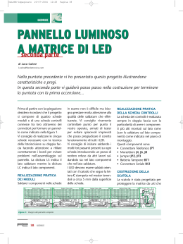
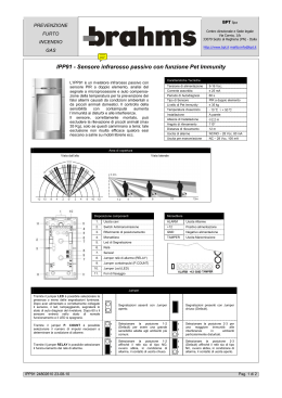
LINCE ITALIA S.p.A.
ART./ITEM:
1608 SHUNI
1608 SHUNI
IT
Scheda interfaccia contatti veloci SHUNI
Manuale di installazione, programmazione ed uso.
- Istruzioni originali -
EN
REG.N.4796
UNI EN ISO 9001:2008
MADE IN ITALY
SHUNI quick contact interface board
Installation, programming and operating manual.
- Translation of original instructions -
LINCE ITALIA S.p.A.
CARATTERISTICHE TECNICHE
Alimentazione
Assorbimento a riposo
TECHNICAL FEATURES
11 ÷ 15 Vcc
7 mA (alimentato con 13,8
Vcc)
Assorbimento in allarme
50 mA (alimentato con 13,8
Vcc)
Scambio relè 1 A max (250V max)
Tempo minimo eccitazione relè 1,5 s
Corrente sulla linea max 300 μA (alimentato con
13,8 Vcc)
Power supply
Consumption in standby
Consumption in alarm
Relay switching Minimum relay energising time Current on the line DESCRIZIONE
DESCRIPTION
La scheda SHUNI è un’interfaccia per la gestione di contatti
per tapparelle (tipo 410 LESW) o contatti a vibrazione inerziali
(tipo 412 MN4) fornita su un supporto plastico che ne facilita il
fissaggio in modo universale.
La scheda SHUNI può essere collegata a centrali di altra marca
e modello che siano conformi alle norme di prodotto in vigore.
Il circuito elettronico della scheda è immune ai disturbi ambientali
e garantisce il corretto funzionamento anche se collegata con
cavi non schermati.
The SHUNI board is an interface to control roller shutter contacts
(type 410 LESW) or inertial vibration contacts (type 412 MN4)
supplied on a plastic support for convenient, universal fastening.
The SHUNI board may be connected to control panels of other
brands and model that comply with current product standards.
The board’s electronic circuit is immune to environmental noise
and assures correct operation even when connected with
unshielded cables.
GESTIONE DI CONTATTI A TAPPARELLA
ROLLER SHUTTER CONTACT CONTROL
La configurazione per la gestione di contatti a tapparella si ottiene
aprendo il Jumper JP4 (“I” in Fig.1) e chiudendo il Jumper JP5
( “T” in Fig.1). In questa modalità il posizionamento del trimmer
“A” risulta ininfluente.
Il jumper JP1 permette di regolare il numero di impulsi da
discriminare (1,2,3,5,7 oppure 9: programmazione ottenuta
chiudendo il jumper JP1 sulla posizione relativa al numero di
impulsi da discriminare).
The configuration to control roller shutter contacts is obtained by
opening Jumper JP4 (“I” in Fig.1) and closing Jumper JP5 ( “T”
in Fig.1).
In this mode the position of trimmer “A” has no influence.
Jumper JP1 makes it possible to adjust the number of impulses
to be discriminated (1,2,3,5,7 or 9: programming obtained by
closing jumper JP1 on the position relevant to the number of
impulses to be discriminated).
N.B.: se la scheda ha in memoria uno o più impulsi ed entro
45 secondi non ne sopraggiungono altri, questa provvede
automaticamente ad azzerarne il conteggio.
Nella figura è riportato un esempio di installazione con contatto
a tapparelle.
Note: if the board has stored one or more impulses and no other
impulses are received within 45 seconds, it automatically resets
the count to zero.
The picture shows an example installation with roller shutter
contact.
11 ÷ 15 Vcc
7 mA (@ 13.8 Vdc)
50 mA (@ 13.8 Vdc)
1 A max (250V max)
1.5 s
max 300 μA (@ 13.8 Vdc)
1
2
3
Fig. 1
1
2
3
2
Uscita N.C. (da collegare su ingresso in centrale)
Alimentazione
Contatto a tapparelle
1
2
3
N.C. Output (to be connected on input in control panel)
Power supply
Roller shutter contact
LINCE ITALIA S.p.A.
GESTIONE DI CONTATTI A VIBRAZIONE
VIBRATION CONTACT CONTROL
La configurazione per la gestione di contatti a vibrazione si ottiene
chiudendo il Jumper JP4 (“I” in Fig.2) e aprendo il Jumper JP5
(“T” in Fig.2). In questa modalità il posizionamento del jumper
JP1 risulta ininfluente.
The configuration to control vibration contacts is obtained by
closing Jumper JP4 (“I” in Fig.2) and opening Jumper JP5 ( “T” in
Fig.2). In this mode the position of jumper JP1 has no influence.
Il trimmer “A” regolerà la sensibilità del contatto a vibrazione con
il criterio:
+ Massima sensibilità girando il trimmer in senso antiorario.
- Minima sensibilità girando il trimmer in senso orario.
Trimmer “A” will adjust sensitivity of the vibration contact with the
criterion:
+ Maximum sensitivity by turning the trimmer anti-clockwise.
- Minimum sensitivity by turning the trimmer clockwise.
Se sono presenti più sensori inerziali collegati in serie sulla stessa
scheda, è importante ricordare che in base al tipo di superficie
sulla quale il sensore è fissato si possono avere sensibilità molto
diverse tra sensore e sensore.
Nella figura è riportato un esempio di installazione con contatto
inerziale.
If several inertial sensors are connected in series on the same
board, it is important to remember that based on the type of
surface on which the sensor is fastened, there may be very
significant differences in sensitivity between sensors.
The picture shows an example installation with inertial contact.
1
2
3
Fig. 2
1
2
3
Uscita N.C. (da collegare su ingresso in centrale)
Alimentazione
Contatto inerziale
1
2
3
N.C. Output (to be connected on input in control panel)
Power supply
Inertial contact
UTILIZZO DEL JUMPER JP6
Tramite l’utilizzo del jumper JP6 (attivo in entrambe le
configurazioni) è possibile regolare il comportamento della
scheda in caso di linea di ingresso perennemente aperta (per
esempio nel caso di fili linea interrotti):
1. Inserendo il Jumper in posizione 2-3 il relè della scheda
rimarrà aperto fino alla chiusura della linea di ingresso.
2. Inserendo il Jumper in posizione 1-2 il relè della scheda
darà un solo impulso di allarme.
N.B: non lasciare mai entrambe le posizioni aperte.
USE OF JUMPER JP6
By using jumper JP6 (active in both configurations) it is possible
to adjust the board’s behaviour in case of input line constantly
open (for example in the event of interrupted line wires):
1. By inserting the Jumper in position 2-3 the board’s relay will
remain open until the input line is closed.
2. By inserting the Jumper in position 1-2 the board’s relay will
issue one alarm impulse only.
Note: never leave both positions open.
LED DI SEGNALAZIONE
La scheda è dotata di due LED: Verde “C” e Rosso “B”.
LED Verde
Emetterà un lampeggio per ogni impulso
percepito dalla scheda (funzione utile in
fase di installazione per verificare il corretto
funzionamento dei contatti),
LED Rosso
Si accende quando si è raggiunta la situazione
di allarme (relè eccitato).
SIGNAL LED
the board is equipped with two LEDs: Green “C” and Red “B”.
Green LED Will flash for each impulse perceived by the
board (useful function during installation to
check proper operation of the contacts)
Red LED
Lights up when the alarm situation has been
reached (energised relay).
3
LINCE ITALIA S.p.A
001530/00413AD
Via Variante di Cancelliera, snc
00040 ARICCIA (Roma)
Tel. +39 06 9301801
Fax +39 06 930180232
[email protected]
Scaricare