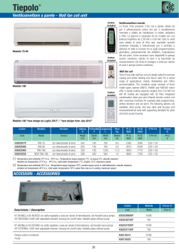
FC/NT
E U R O V E N T
CERTIFIED PERFORMANCE
VENTILCONVETTORI
FAN COILS
VT66000001_01_igb.p65
1
20/02/02, 10.43
INDICE
INDEX
1
2
2.1
3
4
5
6
7
7.1
7.2
8
8.1
9
9.1
9.2
9.3
9.4
9.5
9.6
10
10.1
10.2
10.3
10.4
10.5
10.6
10.7
11
GENERALITA' ................................................................................... 2
COMPONENTI E LORO DESCRIZIONE ........................................... 2
ACCESSORI DISPONIBILI ............................................................. 2
LIMITI DI FUNZIONAMENTO ............................................................ 3
AVVERTENZE DI INSTALLAZIONE .................................................. 3
MANUTENZIONE .............................................................................. 3
CARATTERISTICHE TECNICHE NOMINALI ..................................... 4
PRESTAZIONI .................................................................................. 5
RESA IN RAFFREDDAMENTO ....................................................... 5
RESA IN RISCALDAMENTO ........................................................... 6
DIMENSIONI DI INGOMBRO ............................................................ 7
FILTRO ARIA .................................................................................... 7
SCHEMI ELETTRICI DI COLLEGAMENTO ....................................... 8
FC/NT + TC ...................................................................................... 8
FC/NT + TCT/AW + TC .................................................................... 8
FC/NT + TCTIC/AW + TC ................................................................. 8
FC/NT + TA2 ..................................................................................... 8
FC/NT + TA ....................................................................................... 8
FC/NT + TA inversione centralizzata ............................................... 8
SCHEDE TECNICHE ACCESSORI ................................................. 9 - 13
TCP .................................................................................................. 9
TZ ..................................................................................................... 9
TCT/AW & TCTIC/AW ................................................................... 10-11
TA & TA2 .......................................................................................... 12
TC .................................................................................................... 12
TVAP ................................................................................................ 13
TABELLA DI ABBINAMENTO ACCESSORI ................................... 13
PARTI DI RICAMBIO ..................................................................... 14 - 15
1
2
2.1
3
4
5
6
7
7.1
7.2
8
8.1
9
9.1
9.2
9.3
9.4
9.5
9.6
10
10.1
10.2
10.3
10.4
10.5
10.6
10.7
10
MAIN FEATURES ............................................................................. 2
COMPONENTS AND DESCRIPTIONS ............................................. 2
AVAILABLE ACCESSORIES ........................................................... 2
OPERATING RANGE ........................................................................ 3
INSTALLATION INSTRUCTIONS ..................................................... 3
MAINTENANCE ................................................................................ 3
RATED TECHNICAL FEATURES ...................................................... 4
PERFORMANCE ............................................................................... 5
COOLING CAPACITY ...................................................................... 5
HEATING CAPACITY ....................................................................... 6
OVERALL DIMENSIONS .................................................................. 7
AIR FILTER ...................................................................................... 7
WIRING DIAGRAMS ......................................................................... 8
FC/NT + TC ...................................................................................... 8
FC/NT + T-CT/AW + TC ................................................................... 8
FC/NT + T-CTIC/AW + TC ............................................................... 8
FC/NT + TA2 ..................................................................................... 8
FC/NT + TA ....................................................................................... 8
FC/NT + TA centralised mode selector .......................................... 8
ACCESSORIES TECHNICAL SHEET ............................................ 9 - 13
T-CP ................................................................................................. 9
T-Z .................................................................................................... 9
T-CT/AW & T-CTIC/AW ................................................................. 10-11
TA & TA2 .......................................................................................... 12
TC .................................................................................................... 12
T-VAP ............................................................................................... 13
TABLE OF ACCESSORY COMBINATIONS .................................... 13
SPARE PARTS LIST .................................................................... 14 - 15
1
GENERALITÀ
1
MAIN FEATURES
Anni di studio e ricerche con collaborazioni di Università europee, una progettazione
completamente computerizzata (CAE simulazione numerica e CAD
tridimensionale modellatore di solidi), prove funzionali e prestazionali in laboratori
europei, rappresentano il cammino percorso dalla Galletti S.p.A. per offrire agli
operatori del settore della climatizzazione la nuova serie di ventilconvettori FC/NT
con ventilatore trasversale.
Destinati all'utenza residenziale, commerciale ed alberghiera costituiscono, per
l'estrema silenziosità e compattezza, perfezione di linee e tonalità di colore, il
nuovo standard di riferimento dei terminali di impianto per l'uomo del terzo
millennio.
Le prestazioni dei ventilconvettori Galletti serie FC/NT sono certificate da EUROVENT
Galletti’s new range of FC/NT fan coils with cross-flow fan guarantees wholesalers
and retailers of air-conditioning equipment optimum performance.
The range was developed with the co-operation of European University
researchers, designed with the aid of computers (CAE for numerical simulation
and CAD for three-dimensional modelling) and tested in European laboratories.
Installed in the home, office or in hotels, the FC/NT range of small size fan coils
sets new standards of noise-free operation, trim design and finish.
The performances of Galletti’s FC/NT fan coils series are certified by EUROVENT
which guarantees, within the limits shown below, the reliability of the data
reported IN this technical manual:
- Cooling capacity
- Heating capacity
- Pressure drop on water side
- Power input
- Air flow
- A-weighted sound power level
The certified performances are reported on
Products” in the section Fan coil units.
che garantisce, nelle tolleranze indicate di seguito, l'affidabilità dei dati
riportati sulla presente documentazione tecnica quali:
- Potenzialità in raffreddamento
-5%
- Potenzialità in riscaldamento
-5%
- Perdita di carico lato acqua
+10%
- Potenza assorbita
+10%
- Portata aria
-10 %
- Livelli di potenza sonora ponderata A
+ 0 dB
Le prestazioni certificate sono riportate sulla "Guida dei Prodotti Certificati"
EUROVENT sotto la voce Ventilconvettori.
2
COMPONENTI E LORO DESCRIZIONE
2
-5%
-5%
+10%
+10%
-10%
+ 0 dB
“EUROVENT Directory of Certified
COMPONENTS AND DESCRIPTIONS
Unità base: in acciaio zincato di adeguato spessore, coibentato con pannelli
termoisolanti autoestinguenti (classe 1).
Tutti i modelli sono dotati di kit di installazione (viti a muro).
Batteria di scambio termico: in tubo di rame ed alette in alluminio persianate ad
alta efficienza (louvered fins) con trattamento superficiale idrofilico, bloccate ai
tubi mediante espansione meccanica; il trattamento idrofilico ha funzione antiossidante (evita la formazione di ossido di alluminio in fase di raffreddamento)
e limita le perdite di carico lato aria, contribuendo a mantenere i livelli sonori
estremamente bassi. Lo scambiatore di calore, corredato di collettori in ottone
e valvola di sfiato aria, è sempre fornito con attacchi idraulici a sinistra, non
reversibili.
Ventilatore trasversale: in alluminio, bilanciato staticamente e dinamicamente,
è accoppiato direttamente al motore e ad una bronzina contenuto in un supporto
antivibrante. Il ventilatore è inserito tra parete stabilizzatrice e parete anteriore
convogliatrice realizzate in profilati di alluminio estrusi; la parete anteriore
convogliatrice svolge anche funzione di raccolta della condensa proveniente
dallo scambiatore di calore.
Motore elettrico: a 3 velocità, è dotato di condensatore permanentemente
inserito, protezione termica interna degli avvolgimenti. Rotore e statore sono
costampati con resine termoindurenti in modo da eliminare i rumori magnetici.
Il motore è montato su supporti antivibranti che impediscono la trasmissione
delle vibrazione all'unità base. Grado di protezione IP42, avvolgimenti in classe
B.
Bearing Structure: made of thick galvanised steel, heat insulated with selfextinguishing (class 1) panels. All models come with installation kit (wall screws).
Heat exchanger: made of copper pipes with surface treated louvered aluminium
fins fitted to pipes by expansion; surface treatment to avoid rusting of aluminium
and to reduce air side pressure drops, keeping noise to a minimum. The heat
exchanger, with brass manifolds and air vent valve, is fitted with non-reversible
left-side hydraulic connections on all models.
Cross-flow fan: in aluminium, statically and dynamically balanced, directly
coupled to motor and to a slip bearing in anti-vibration housing. The fan is fitted
between stabilising rear plate and extruded aluminium front plate conveyor; the
front plate conveyor also collects condensation from the heat exchanger.
Electric motor: 3-speed, with permanently connected capacitor, fuse protecting
windings from overheating. Rotor and stator pressed with thermosetting resin to
avoid magnetic noise. Motor housed on anti-vibration supports (avoiding vibration
of the bearing unit). IP42 fuses and class B windings.
Cabinet: a thick steel plate cover with ABS sides, complete with air outlet grills
and side doors giving access to the control panel in heat-resistant ABS. Grills can
be swivelled 180°. Cabinet surface finish in RAL 9001 paint.
Control panel: fitted under the access door on the right-hand side; on-off switch
and speed switch.
Filtering unit: polypropylene honeycomb air filter in galvanised steel frame.
2.1
2.1
ACCESSORI DISPONIBILI
T-CP
Chiusura posteriore
T-CT/AW,
Comando elettronico
T-CTIC/AW
Comando elettronico
TA
Termostato ambiente
TA2
Termostato ambiente
TC
Termostato di consenso
T-VAP
Vaschetta ausiliaria
T-Z
Zoccoli di copertura
Per ulteriori indicazioni vedere capitolo 10 "SCHEDE TECNICHE ACCESSORI".
VT66000001 - rev. 01
VT66000001_01_igb.p65
AVAILABLE ACCESSORIES
T-CP
T-CT/AW
T-CTIC/AW
TA
TA2
TC
T-VAP
T-Z
See section 10
Rear panel
Electronic control
Electronic control
Room thermostat (heating only)
Room thermostat (heating and cooling)
Fan stop thermostat
Auxiliary drip tray
Covering feet
“ACCESSORIES TECHNICAL SHEET” for further information
2
2
20/02/02, 10.43
3
2
1
1
GRIGLIA DI USCITA ARIA
AIR OUTLET GRILL
2
SCAMBIATORE DI CALORE
HEAT EXCHANGER
3
PANNELLO DI COMANDO
CONTROL PANEL
4
MOTORE
MOTOR
5
VENTILATORE TRASVERSALE
CROSS-FLOW FAN
6
FILTRO ARIA
AIR FILTER
7
SCARICO CONDENSA
DRAIN OUTLET
8
MOBILE DI COPERTURA
CABINET
®
8
4
7
5
6
3
LIMITI DI FUNZIONAMENTO
Temperatura minima acqua
Temperatura massima acqua
Massima pressione di esercizio
Temperatura minima aria aspirata
Temperatura massima aria aspirata
Tensione di alimentazione
4
3
5°C
95°C
10 bar
5°C
43°C
230 V+/- 10%
AVVERTENZE DI INSTALLAZIONE
4
I ventilconvettori vanno installati in una posizione tale da riscaldare e raffrescare
uniformemente il locale, su pareti che ne reggano il peso.
Installare gli eventuali accessori sull’apparecchio standard prima di procedere
alla sua installazione.
Per l'installazione e l'uso di eventuali accessori si rimanda alle schede tecniche
degli stessi.
Mantenere intorno al ventilconvettore lo spazio necessario a consentirne il
corretto funzionamento e tale da permettere di effettuare operazioni di
manutenzione ordinaria e straordinaria (vedere il capitolo "dimensioni di
ingombro").
Nel caso di fermate invernali scaricare l’acqua dall’impianto onde evitare
danneggiamenti dovuti a formazione di ghiaccio; se vengono utilizzate soluzioni
antigelo verificare e il punto di congelamento della miscela e le prestazioni
dell'unità utilizzando la tabella riportata al centro dell a pagina.
5
OPERATING RANGE
Minimum water temperature
Maximum water temperature
Maximum operating pressure
Minimum inlet air temperature
Maximum inlet air temperature
Power supply
5° C
95° C
10 bar
5° C
43° C
230 V+/- 10%
INSTALLATION SUGGESTIONS
Fan coils should be fitted in areas where heating and cooling of the room is
uniform.
Ensure the wall bears the weight of the fan coil.
Fit any accessories to the standard model before installation.
See technical data sheets for the fitting of the accessories.
Keep sufficient space clear around the fan coil for proper operation and for ordinary
and emergency maintenance (see section on “overall dimensions”).
For winter shut-down water should be drained off in order to prevent damage due
to freezing.
If anti-freeze solutions are used check the freezing point and machine performance on the table at the centre of the page.
Percentuale di glicole in peso
Glycol percentage in weight
Temperatura di congelamento (°C)
Freezing temperature (°C)
Variazione della potenza resa
Capacity correction factor
Variazione della perdita di carico
Pressure drop correction factor
0
10
20
30
40
0
-4
-10
-16
-24
1,00
0,97
0,92
0,87
0,82
1,00
1,05
1,10
1.15
1,20
MANUTENZIONE
5
MAINTENANCE
I ventilconvettori FC/NT non necessitano di particolari manutenzioni: è sufficiente
la pulizia periodica del filtro aria.
Il motore non necessita di manutenzione in quanto dotato di cuscinetti
autolubrificanti.
Nel caso sia necessario sostituire il filtro aria, utilizzare ricambi originali; il
modello di ventilconvettore è individuabile sulla targhetta di identificazione posta
sulla fiancata interna. Le dimensioni dei filtri aria sono riportate a pagina 10.
Per tutte le operazioni di manutenzione e pulizia riferirsi al manuale di "installazione
uso e manutenzione" di corredo al prodotto.
FC/NT fan coils do not require any special maintenance operations; the air filter
should be cleaned from time to time. The motor is fitted with self-lubricating
bearings and does not require maintenance.
Should the air filter need replacing, use only original spare parts. The model type
can be read off the inside nameplate on the side of the machine. See page 10 for
filter dimensions.
Use the “installation, operations and maintenance” handbook for all maintenance
and cleaning operations.
I dati tecnici e dimensionali riportati nella presente documentazione possono subire variazioni
orientate al miglioramento del prodotto.
The technical and dimension data reported in this manual may be modified in view of any
product improvement.
VT66000001- rev. 01
3
VT66000001_01_igb.p65
3
20/02/02, 10.43
6
CARATTERISTICHE TECNICHE NOMINALI
6
Modello - Model
Potenza totale raffreddamento
1
Potenza sensibile raffreddamento
1
Total cooling capacity
1
Sensible cooling capacity
1
RATED TECHNICAL FEATURES
Vr
SI - non SI
FC/NT 11
FC/NT 22
FC/NT 33
FC/NT 44
3
Watt - Frig/h
968 - 832
1355 - 1165
2040 - 1754
2524 - 2171
3
Watt - Frig/h
757 - 651
1137 - 978
1710 - 1471
2083 - 1791
Portata acqua
Water flow
3
l/s - l/h
0,046 - 166
0,065 - 234
0,097 - 349
0,120 - 432
Perdite di carico
Pressure drop
3
kPa - m H2O
11,77 - 1,20
15,72 - 1,60
9,86 - 1,01
14,16 - 1,44
3
Watt - kcal/h
1316 - 1132
1886 - 1622
2926 - 2516
3492 - 3003
3
l/s - l/h
0,046 - 166
0,065 - 234
0,097 - 349
0,120 - 432
Potenza termica riscaldamento
2
Heating capacity
Portata acqua
2
Water flow
Perdita di carico
Pressure drop
Potenza termica riscaldamento
3
Heating capacity
3
3
kPa - m H2O
10,41 - 1,06
13,43 - 1,37
8,20 - 0,84
11,99 - 1,22
3
Watt - kcal/h
2252 - 1937
3247 - 2792
5072 - 4362
6000 - 5160
Portata acqua
Water flow
3
l/s - l/h
0,055 - 198
0,079 - 284
0,124 - 446
0,146 - 526
Perdita di carico
Pressure drop
3
kPa - m H2O
13,22 - 1,35
17,65 - 1,80
11,68 - 1,19
15,79 - 1,61
Contenuto acqua batteria
Heat exchanger water content
-
l
0,49
0,66
0,83
1,00
Attacchi idraulici
Hydraulic connections
-
φ
1/2"
1/2"
1/2"
1/2"
Portata aria
Air flow
Tensione di alimentazione
Power supply
Corrente di esercizio
Operating current
Potenza assorbita
Potenza sonora
Power input
4
Pressione sonora
Sound power level
5
4
Sound pressure level
Dimensioni
Dimensions
Altezza
Height
5
3
3
l/s - m /h
47 - 169
76 - 274
114 - 410
138 - 497
2
l/s - m3/h
37 - 133
60 - 216
90 - 324
111 - 400
3
1
l/s - m /h
26 - 94
41 - 148
62 - 223
77 - 277
-
V / f / Hz
230 /1 / 50
230 /1 / 50
230 /1 / 50
230 /1 / 50
3
A
0,08
0,10
0,12
0,14
2
A
0,07
0,01
0,11
0,11
1
A
0,09
0,01
0,11
0,10
3
Watt
16
22
35
39
2
Watt
12
18
26
28
1
Watt
9
11
17
19
3
dB(A)
42
44
48
53
2
dB(A)
37
40
42
47
1
dB(A)
29
33
35
39
3
dB(A)
34 - 37
36 - 39
40 - 43
45 - 48
2
dB(A)
29 - 32
32 - 35
34 - 37
39 - 42
1
dB(A)
21 - 24
25 - 28
27 - 30
31 - 34
-
mm
560
560
560
560
Lunghezza
Lenght
-
mm
600
720
840
960
Profondità
Width
-
mm
197
197
197
197
Peso netto indicativo
Approx. net weight
-
kg
16
19
22
25
Le prestazioni sono riferite alle seguenti condizioni:
Rated capacity determined at the following conditions:
1 Temperatura ingresso acqua 7°C
Temperatura uscita acqua 12°C
Temperatura ingresso aria 27°C B.S., 19°C B.U. (47% UR)
1 Water inlet temperature 7°C
Water outlet temperature 12°C
Inlet air inlet temperature 27°C D.B., 19°C W.B. (47% R.H.)
2 Temperatura acqua ingresso 50°C
Portata acqua come in raffreddamento
Temperatura ingresso aria 20°C
2 Inlet water temperature 50°C
Water flow rate same as in cooling mode,
Inlet air temperature 20°C
3 Temperatura ingresso acqua 70°C
Temperatura uscita acqua 60°C
Temperatura ingresso aria 20°C
4 Potenza sonora rilevata secondo le EN 23741 e EN 23742
3 Water inlet temperature 70°C
Water outlet temperature 60°C
Air inlet temperature 20°C
4 Sound power measured according to EN 23741 and EN 23742
5 Pressione sonora calcolata alla distanza di 1 m, nella prima colonna con fattore di
direzionalità pari a 2 e nella seconda colonna pari a 4
Vr Velocità di ventilazione:
3=massima
2=media
1=minima
VT66000001 - rev. 01
VT66000001_01_igb.p65
5 Sound pressure level calculated at 1 m distance, in first column with directionality factor
equal to 2 and in second column equal to 4
Vr Fan speed:
3=maximum
2=medium
1=minimum
4
4
20/02/02, 10.43
7
PRESTAZIONI
7
PERFORMANCES
7.1
RESA IN RAFFREDDAMENTO
7.1
COOLING CAPACITY
Legenda:
Tbs1 Temperatura ingresso aria bulbo secco
Tbu1 Temperatura ingresso aria bulbo umido
Tw1 Temperatura ingresso acqua
Tw2 Temperatura uscita acqua
Vr Velocità di ventilazione: 3=massima, 2=media, 1=minima
PFT Potenzialità raffreddamento totale
PFS Potenzialità raffreddamento sensibile
Q w Portata acqua
∆ p w Perdita di carico lato acqua
Tbs1 / Tbu1 (UR1)
°C
Tw1 / Tw2
°C
Legend:
Tbs1 Inlet air temperature D.B.
Tbu1 Inlet air temperature W.B.
Tw1 Inlet water temperature
Tw2 Outlet water temperature
Vr Fan speed: 3=maximum, 2=medium, 1=minimum
PFT Total cooling capacity
PFS Sensible cooling capacity
Q w Water flow rate
∆ p w Pressure drop - water side
25 / 18 (51%)
6 / 11
Vr
PFT
7 / 12
PFS
Qw
W
Frig/h
W
Frig/h
l/s
l/h
∆pw
kPa
m H2O
PFT
PFS
Qw
W
Frig/h
W
Frig/h
l/s
l/h
kPa
∆p w
m H2O
FC/NT 11
3
2
1
931
785
600
801
675
516
706
579
428
607
498
368
0,044
0,037
0,029
158
133
104
11,05
8,21
5,12
1,13
0,84
0,52
814
687
526
700
591
452
659
539
397
567
464
341
0,039
0,033
0,025
140
119
90
8,69
6,46
4,05
0,89
0,66
0,41
FC/NT 22
3
2
1
1298
1102
825
1116
948
710
1053
866
622
906
745
535
0,062
0,053
0,039
223
191
140
14,67
11,01
6,63
1,50
1,12
0,68
1116
945
702
960
813
604
982
804
572
845
691
492
0,053
0,045
0,033
191
162
119
11,19
8,37
4,97
1,14
0,85
0,51
FC/NT 33
3
2
1
1951
1649
1228
1678
1418
1056
1583
1298
934
1361
1116
803
0,093
0,079
0,059
335
284
212
9,17
6,83
4,08
0,94
0,70
0,42
1668
1402
1026
1434
1206
882
1472
1200
852
1266
1032
733
0,080
0,067
0,049
288
241
176
6,93
5,11
2,96
0,71
0,52
0,30
FC/NT 44
3
2
1
2423
2091
1599
2084
1798
1375
1933
1620
1189
1662
1393
1023
0,115
0,100
0,076
414
360
274
13,25
10,25
6,40
1,35
1,05
0,65
2112
1820
1384
1816
1565
1190
1811
1512
1102
1557
1300
948
0,101
0,087
0,066
364
313
238
10,36
7,99
4,95
1,06
0,81
0,50
Tw1 / Tw2
°C
8 / 13
9 / 14
W
Frig/h
W
Frig/h
l/s
l/h
∆pw
kPa
m H2O
Vr
PFT
PFS
Qw
PFT
PFS
Qw
W
Frig/h
W
Frig/h
l/s
l/h
kPa
∆p w
m H2O
FC/NT 11
3
2
1
688
582
449
592
501
386
610
497
365
525
427
314
0,033
0,028
0,021
119
101
76
6,44
4,80
3,05
0,66
0,49
0,31
385
331
558
469
340
480
403
292
0,027
0,022
0,018
97
79
65
4,44
3,27
2,31
0,45
0,33
0,24
FC/NT 22
3
2
1
613
527
853
721
538
734
620
463
0,041
0,034
0,029
148
122
104
6,95
5,18
3,90
0,71
0,53
0,40
-
-
783
663
524
673
570
451
0,037
0,032
0,025
133
115
90
5,95
4,45
2,95
0,61
0,45
0,30
FC/NT 33
3
2
1
850
731
1283
1080
785
1103
929
675
0,061
0,051
0,041
220
184
148
4,35
3,22
2,12
0,44
0,33
0,22
-
-
1175
987
768
1011
849
660
0,056
0,047
0,037
202
169
133
3,71
2,73
1,76
0,38
0,28
0,18
FC/NT 44
3
2
1
1773
1522
1138
1525
1309
979
1682
1397
1005
1447
1201
864
0,085
0,073
0,054
306
263
194
7,59
5,81
3,49
0,77
0,59
0,36
-
-
1425
1223
923
1226
1052
794
0,068
0,058
0,044
245
209
158
5,15
3,94
2,41
0,53
0,40
0,25
Tbs1 / Tbu1 (UR1)
°C
Tw1 / Tw2
°C
27 / 19 (47%)
6 / 11
Vr
PFT
7 / 12
PFS
Qw
W
Frig/h
W
Frig/h
l/s
l/h
∆pw
kPa
m H2O
PFT
PFS
Qw
W
Frig/h
W
Frig/h
l/s
l/h
kPa
∆p w
m H2O
FC/NT 11
3
2
1
1081
910
694
930
783
597
803
658
486
691
566
418
0,052
0,043
0,033
187
156
119
14,36
10,62
6,61
1,46
1,08
0,67
968
816
623
832
702
536
757
619
456
651
532
392
0,046
0,039
0,030
166
140
108
11,77
8,73
5,45
1,20
0,89
0,56
FC/NT 22
3
2
1
1528
1299
976
1314
1117
839
1204
991
715
1035
853
615
0,073
0,062
0,047
263
223
169
19,51
14,68
8,91
1,99
1,50
0,91
1355
1151
864
1165
990
743
1137
933
669
978
802
575
0,065
0,055
0,041
234
198
148
15,72
11,82
7,15
1,60
1,21
0,73
FC/NT 33
3
2
1
2307
1955
1469
1984
1681
1263
1814
1491
1079
1560
1282
928
0,110
0,093
0,070
396
335
252
12,30
9,19
5,57
1,25
0,94
0,57
2040
1726
191
1754
1484
164
1710
1400
1007
1471
1204
866
0,097
0,082
0,062
349
295
223
9,86
7,35
4,43
1,01
0,75
0,45
FC/NT 44
3
2
1
2822
2437
1868
2427
2096
1606
2199
1845
1358
1891
1587
1168
0,134
0,116
0,089
482
418
320
17,31
13,40
8,41
1,77
1,37
0,86
2524
2180
1669
2171
1875
1435
2083
1742
1276
1791
1498
1097
0,120
0,104
0,080
432
374
288
14,16
10,95
6,86
1,44
1,12
0,70
Tw1 / Tw2
°C
8 / 13
9 / 14
W
Frig/h
W
Frig/h
l/s
l/h
∆pw
kPa
m H2O
Vr
PFT
PFS
Qw
PFT
PFS
Qw
W
Frig/h
W
Frig/h
l/s
l/h
kPa
∆p w
m H2O
FC/NT 11
3
2
1
848
716
548
729
616
471
710
579
425
611
498
366
0,040
0,034
0,026
144
122
94
9,27
6,90
4,32
0,95
0,70
0,44
719
608
466
618
523
401
662
538
393
569
463
338
0,034
0,029
0,022
122
104
79
6,91
5,16
3,23
0,70
0,53
0,33
FC/NT 22
3
2
1
1170
992
740
1006
853
636
1067
872
621
918
750
534
0,056
0,047
0,035
202
169
126
12,09
9,06
5,42
1,23
0,92
0,55
627
539
929
786
578
799
676
497
0,044
0,037
0,030
158
133
108
8,03
5,99
4,04
0,82
0,61
0,41
FC/NT 33
3
2
1
1752
1478
1092
1507
1271
939
1601
1305
929
1377
1122
799
0,084
0,070
0,052
302
252
187
7,51
5,57
3,28
0,77
0,57
0,33
-
-
1402
1181
881
1206
1016
758
0,067
0,056
0,042
241
202
151
5,05
3,75
2,24
0,52
0,38
0,23
FC/NT 44
3
2
1
2206
1904
1452
1897
1637
1249
1962
1636
1190
1687
1407
1023
0,105
0,091
0,069
378
328
248
11,12
8,60
5,35
1,13
0,88
0,55
1208
1039
1680
1445
1097
1445
1243
943
0,080
0,069
0,058
288
248
209
6,86
5,27
3,85
0,70
0,54
0,39
VT66000001- rev. 01
5
VT66000001_01_igb.p65
5
20/02/02, 10.43
7.2
RESA IN RISCALDAMENTO
7.2
Legenda:
Tbs1 Temperatura ingresso aria bulbo secco
Tw1 Temperatura ingresso acqua
Tw2 Temperatura uscita acqua
Vr Velocità di ventilazione:
3=massima - 2=media - 1=minima
PT Potenzialità termica resa
Q w Portata acqua
∆ p w Perdita di carico lato acqua
Tbs1
°C
Tw1 / Tw2
°C
HEATING CAPACITY
Legend:
Tbs1 Inlet air temperature D.B.
Tw1 Inlet water temperature
Tw2 Outlet water temperature
Vr Fan speed:
3=maximum - 2=medium - 1=minimum
PT Heating capacity
Q w Water flow rate
∆ p w Pressure drop - water side
19
50 / 45
Vr
60 / 50
PT
Qw
W
kcal/h
l/s
l/h
∆p w
kPa
m H2O
PT
Qw
W
kcal/h
l/s
l/h
kPa
∆pw
m H2O
FC/NT 11
3
2
1
1418
1177
880
1219
1012
757
0,069
0,057
0,043
248
205
155
20,85
15,05
9,05
2,13
1,54
0,92
1798
1499
1125
1546
1289
968
0,044
0,036
0,027
158
130
97
9,17
6,67
4,04
0,94
0,68
0,41
FC/NT 22
3
2
1
2048
1729
1294
1761
1487
1113
0,099
0,084
0,063
356
302
227
27,96
20,81
12,52
2,85
2,12
1,28
2580
2186
1640
2219
1880
1410
0,063
0,053
0,040
227
191
144
12,15
9,09
5,49
1,24
0,93
0,56
FC/NT 33
3
2
1
3197
2687
2006
2749
2311
1725
0,155
0,130
0,097
558
468
349
18,49
13,63
8,18
1,89
1,39
0,83
4031
3403
2552
3467
2927
2195
0,098
0,083
0,062
353
299
223
8,05
5,97
3,61
0,82
0,61
0,37
FC/NT 44
3
2
1
3782
3233
2443
3253
2780
2101
0,183
0,156
0,118
659
562
425
24,99
18,99
11,64
2,55
1,94
1,19
4779
4099
3119
4110
3525
2682
0,116
0,100
0,076
418
360
274
10,91
8,35
5,17
1,11
0,85
0,53
Tw1 / Tw2
°C
70 / 60
Vr
90 / 70
PT
Qw
W
kcal/h
l/s
l/h
∆p w
kPa
m H2O
PT
Qw
W
kcal/h
l/s
l/h
kPa
∆pw
m H2O
FC/NT 11
3
2
1
2307
1917
1437
1984
1649
1236
0,056
0,047
0,035
202
169
126
13,77
9,97
6,01
1,40
1,02
0,61
3086
2575
1941
2654
2215
1669
0,038
0,032
0,024
137
115
86
6,59
4,80
2,92
0,67
0,49
0,30
FC/NT 22
3
2
1
3325
2812
2108
2860
2418
1813
0,081
0,069
0,051
292
248
184
18,41
13,73
8,29
1,88
1,40
0,85
4419
3751
2825
3800
3226
2430
0,054
0,046
0,054
194
166
194
8,71
6,53
3,98
0,89
0,67
0,41
FC/NT 33
3
2
1
5195
4370
3272
4468
3758
2814
0,127
0,107
0,080
457
385
288
12,19
9,01
5,42
1,24
0,92
0,55
6912
5839
4400
5944
5022
3784
0,085
0,072
0,054
306
259
194
5,77
4,30
2,62
0,59
0,44
0,27
FC/NT 44
3
2
1
6143
5258
3982
5283
4522
3425
0,150
0,128
0,097
540
461
349
16,47
12,53
7,70
1,68
1,28
0,79
8184
7028
5356
7038
6044
4606
0,100
0,086
0,066
360
310
238
7,82
5,99
3,72
0,80
0,61
0,38
Tbs1
°C
Tw1 / Tw2
°C
20
50 / 45
Vr
60 / 50
PT
Qw
W
kcal/h
l/s
l/h
∆p w
kPa
m H2O
PT
Qw
W
kcal/h
l/s
l/h
kPa
∆pw
m H2O
FC/NT 11
3
2
1
1365
1133
848
1174
974
729
0,066
0,055
0,041
238
198
148
19,52
14,09
8,47
1,99
1,44
0,86
1745
1454
1091
1501
1250
938
0,042
0,035
0,027
151
126
97
8,70
6,32
3,83
0,89
0,64
0,39
FC/NT 22
3
2
1
1971
1665
1246
1695
1432
1072
0,095
0,081
0,060
342
292
216
26,17
19,48
11,71
2,67
1,99
1,19
2503
2119
1590
2153
1822
1367
0,061
0,051
0,039
220
184
140
11,51
8,61
5,21
1,17
0,88
0,53
FC/NT 33
3
2
1
3078
2586
1932
2647
2224
1662
0,149
0,125
0,094
536
450
338
17,30
12,76
7,66
1,76
1,30
0,78
3909
3301
2474
3362
2839
2128
0,095
0,080
0,060
342
288
216
7,63
5,66
3,42
0,78
0,58
0,35
FC/NT 44
3
2
1
3642
3113
2353
3132
2677
2024
0,176
0,151
0,114
634
544
410
23,39
17,78
10,89
2,39
1,81
1,11
4638
3979
3027
3989
3422
2603
0,113
0,097
0,073
407
349
263
10,35
7,91
4,90
1,06
0,81
0,50
Tw1 / Tw2
°C
70 / 60
Vr
90 / 70
PT
Qw
W
kcal/h
l/s
l/h
∆p w
kPa
m H2O
PT
Qw
W
kcal/h
l/s
l/h
kPa
∆pw
m H2O
FC/NT 11
3
2
1
2252
1872
1403
1937
1610
1207
0,055
0,046
0,034
198
166
122
13,22
9,56
5,77
1,35
0,98
0,59
3030
2530
1905
2606
2176
1638
0,037
0,031
0,023
133
112
83
6,38
4,65
2,83
0,65
0,47
0,29
FC/NT 22
3
2
1
3247
2746
2059
2792
2362
1771
0,079
0,067
0,050
284
241
180
17,65
13,16
7,95
1,80
1,34
0,81
4339
3683
2773
3732
3167
2385
0,053
0,045
0,034
191
162
122
8,43
6,33
3,85
0,86
0,65
0,39
FC/NT 33
3
2
1
5072
4268
3193
4362
3670
2746
0,124
0,104
0,078
446
374
281
11,68
8,63
5,20
1,19
0,88
0,53
6785
5732
4318
5835
4930
3713
0,083
0,070
0,053
299
252
191
5,59
4,16
2,53
0,57
0,42
0,26
FC/NT 44
3
2
1
6000
5135
3887
5160
4416
3343
0,146
0,125
0,095
526
450
342
15,79
12,02
7,39
1,61
1,23
0,75
8036
6899
5257
6911
5933
4521
0,099
0,085
0,064
356
306
230
7,57
5,80
3,60
0,77
0,59
0,37
VT66000001 - rev. 01
VT66000001_01_igb.p65
6
6
20/02/02, 10.43
8
DIMENSIONI DI INGOMBRO
8
OVERALL DIMENSIONS
Legenda:
Legend:
1
Valvola di sfiato aria
1
Air vent valve
2
Collettore di ingresso acqua 1/2" femmina
2
Water inlet manifold 1/2" female
3
Collettore di uscita acqua 1/2" femmina
3
Water outlet manifold 1/2" female
4
Scarico condensa Φ 17 mm
4
Condensate drainage F 17 mm
5
Spazio utile per gli attacchi idraulici
5
Space for hydraulic connections
6
Asole per il fissaggio alla parete 9 x 20mm
6
9 x 20 mm holes for wall installation
7
Spazio utile per i cablaggi elettrici
7
Space for electric cables
197
A
80
B
108
108
1
2
4
91
272
369
451
308
559
3
116
5
8.1
6
7
154
FC/NT
A
B
C
11
600
384
355
22
720
504
475
33
840
624
595
44
960
744
715
FILTRI ARIA
8.1
AIR FILTERS
C
VT66000001- rev. 01
7
VT66000001_01_igb.p65
7
20/02/02, 10.43
9
SCHEMI ELETTRICI DI COLLEGAMENTO
9
WIRING DIAGRAMS
Note schemi elettrici
Attenzione! Prima di iniziare i collegamenti elettrici togliere tensione al
ventilconvettore.
I collegamenti tratteggiati vanno eseguiti dall’installatore.
Per ogni ventilconvettore prevedere una presa di corrente singola ed un interruttore (IL) con fusibile (F) di protezione adeguato.
Wiring diagram notes
Warning! Turn off the power supply before beginning any wiring connections.
The dashed lines connections must be carried out by the installer.
Use a single socket and switch (IL) with suitable protection fuse (F) for each fancoil.
Legend:
BK
BU
CC
T-CT/AW
T-CTIC/AW
F
GNYE
IC
Legend:
BK
BU
CC
T-CT/AW
T-CTIC/AW
F
GNYE
IC
IL
M
RD
SFC
TA
TA2
TC
WH
Nero = velocità massima
Blu = velocità media
Commutatore di velocità incorporato
Comando elettronico di regolazione (ACCESSORIO)
Comando elettronico di regolazione (ACCESSORIO)
Fusibile di protezione (NON FORNITO)
Giallo/verde=terra
Invertitore di funzionamento centralizzato (NON FORNITO):
=Estate,
=Inverno
Interruttore di linea (NON FORNITO)
Motore ventilatore
Rosso = velocità minima
Selettore di funzionamento centralizzato (NON FORNITO):
raffrescamento (APERTO) riscaldamento (CHIUSO)
Termostato ambiente (ACCESSORIO)
Termostato ambiente (ACCESSORIO)
Termostato di consenso (ACCESSORIO)
Bianco = comune
IL
M
RD
SFC
TA
TA2
TC
WH
Black = maximum speed
Blue = medium
Built-in speed selection switch
Electronic control panel (ACCESSORY)
Electronic control panel (ACCESSORY)
Protection fuse (NOT SUPPLIED)
Yellow/Green = hearth connection
=cooling,
=heating
Centralised mode selector (NOT SUPPLIED):
Mains switch (NOT SUPPLIED)
Fan motor
Red = minimum
Centralised control switch (NOT SUPPLIED): cooling (open), heating (closed)
Room thermostat (ACCESSORY)
Room thermostat (ACCESSORY)
Fan stop thermostat (ACCESSORY)
White = common
9.1 Ventilconvettore FC/NTcon comando standard 9.2 Ventilconvettore FC/NT con comando elettronico 9.3 Ventilconvettore FC/NT con comando elettronico Te termostato di consenso TC
T-CT/AW e termostato di consenso TC
CTIC/AW e termostato di consenso TC
FC/NT fan coil with standard control and TC fan
FC/NT fan coil with T-CT/AW electronic control
FC/NT fan coil with T-CTIC/AW electronic control and
stop thermostat
and TC fan stop thermostat
TC fan stop thermostat
230 - 1 - 50
SFC
IC
L
N
WH BK BU RD
L
N
1
10 WH BK BU RD
L
N
1
10 WH BK BU RD
CC
T-CTIC/AW
IL
M
1~
TC
IL
TC
RD
BU
TC
M
1~
M
1~
L N
230 - 1 - 50
L N
230 - 1 - 50
L N
230/1/50
BK
F
WH
RD
BU
WH
F
IL
BK
RD
BK
WH
BU
T-CT/AW
F
9.4 Ventilconvettore FC/NT con comando standard 9.5 Ventilconvettore FC/NT con comando standard 9.6 Ventilconvettore FC/NT con comando standard e
e termostato ambiente TA2
e termostato ambiente TA
termostato ambiente TA con selettore di
FC/NT fan coil with standard control and TA2
FC/NT fan coil with standard control and TA
funzionamento centralizzato
thermostat for room temperature
thermostat for room temperature
FC/NT fan coil with standard control and TA2
thermostat for room temperature with centralised
mode selector
L
WH BK BU RD
N
M
1~
M
1~
L
5
N
230V / 1~ / 50Hz
L
1
6
3
N
230V / 1~
50Hz
230V / 1~ / 50Hz
2
IC
TA
TA2
1
3
TA
VT66000001 - rev. 01
VT66000001_01_igb.p65
8
8
RD
IL
M
1~
N
BU
F
IL
4
WH BK BU RD
CC
RD
BU
BK
WH
F
IL
1
N
CC
RD
BK
WH
BU
CC
F
L
WH BK BU RD
BK
N
WH
L
20/02/02, 10.44
2
L
10
10.1
SCHEDE TECNICHE ACCESSORI
T-CP: CHIUSURA POSTERIORE
Questo accessorio viene fornito per l’installazione del ventilconvettore con parte
posteriore in vista. Ad esempio: installazione a ridosso di pareti vetrate. E’
composto da una chiusura posteriore superiore e da una chiusura posteriore
inferiore, entrambe di colore RAL 9001. I ventilconvettori che utilizzano la chiusura
posteriore non possono essere fissati a parete e devono essere dotati di
zoccoli di sostegno e copertura. Al ricevimento della merce controllare che tutti
i componenti del kit siano presenti nell’imballo e verificarne lo stato.
Il kit è composto da: n° 1 chiusura posteriore superiore, n° 1 chiusura posteriore
inferiore e n° 8 viti autofilettanti 4,25 x 9,5.
Installazione
Attenzione! Montare la chiusura posteriore sul ventilconvettore prima di
procedere alla sua installazione idraulica ed elettrica.
1. Smontare la cornicie copri-comando ed il mobile di copertura agendo sulle
4 viti di fissaggio.
2. Montare la chiusura inferiore al distanziale degli zoccoli di copertura.
3. Montare la chiusura superiore al posteriore dell’unità base.
Come ordinare
Chiusura posteriore T-CP per FC/NT 11 codice
1800193
Chiusura posteriore T-CP per FC/NT 22 codice
1800194
Chiusura posteriore T-CP per FC/NT 33 codice
1800195
Chiusura posteriore T-CP per FC/NT 44 codice
1800196
10.2
ACCESSORIES TECHNICAL SHEET
10.1
T-CP: REAR CLOSURE PANELS
This accessory is supplied for fan coils that are to be ounted against a glass wall.
There are two rear panels, upper and lower, both in colour RAL 9001.
Fan coils which use the rear closure panel cannot be wall mounted, and require
supporting covering feet. When you receive the goods, make sure all the kit
components are present and in good order.
The kit comprises: 1 (one) upper rear closure panel, 1 (one) lower rear closure
panel, 8 (eight) self-tapping screws, 4,25 x 9,5.
Installation
Warning! Fix the rear closure panel to the fan coil before making hydraulic or
electrical connections.
1. Undo the four screws which hold the control panel cover frame in place, and
remove it.
2. Attach the lower closure panel to the spacer of the covering feet.
3. Attach the upper closure to the rear of the bearing unit.
How to order
T-CP rear closure panel for FC/NT 11 code
1800193
T-CP rear closure panel for FC/NT 22 code
1800194
T-CP rear closure panel for FC/NT 33 code
1800195
T-CP rear closure panel for FC/NT 44 code
1800196
T-Z: ZOCCOLI DI COPERTURA
10.2
Gli zoccoli di copertura vengono forniti in coppia e sono costituiti dai distanziali
per il fissaggio all’unità base e dalle coperture esterne per il fissaggio al mobile.
Si utilizzano per mascherare le tubazioni idrauliche e quando sia impossibile
fissare il ventilconvettore alla parete.
L'altezza degli zoccoli di copertura è di 100 mm.
Il kit è composto da:
n°2 sostegni
n° 2 zoccoli di copertura
n° 10 viti autofilettanti 4,25 x 9,5
Installazione
1. Smontare la cornicie copri-comando ed il mobile di copertura agendo sulle
4 viti di fissaggio.
2. Rimuovere i distanziali di allineamento come indicato in figura 1TZ
3. Montare i distanziali (sinistro e destro) sulle rispettive fiancate dell’unità base
come in figura 2TZ.
4. Adagiare il mobile di copertura su un cartone (ad esempio l’imballo del
ventilconvettore); montare gli zoccoli di copertura al mobile fissandoli alle
fiancate in plastica (2 viti) ed al pannello frontale (1 vite) del mobile stesso (figura
3TZ).
Come ordinare: zoccoli di copertura T-Z codice 1800197
1TZ
10
T-Z: COVERING FEET
The covering feet are supplied as pairs, and comprise a spacer for fixing to the
bearing unit and an external cover for fixing to the cabinet.
These feet are used to cover the piping, and whenever it is impossible to attach
the fan coil to the wall.
Each cover plate is 100 mm high.
Each kit comprises:
2 (two) supports
2 (two) covering feet
10 (ten) self-tapping screws, 4,25 x 9,5
Installation
1. Undo the 4 screws to remove the control panel frame and cabinet.
2. Remove the alignment spacers as indicated in figure 1TZ.
3. Place the spacers on the left- and right-hand sides of the bearing unit as shown
in figure 2TZ.
4. Place the cabinet on some spare piece of cardboard (e.g. the packaging), then
screw the covering feet to the plastic sides (2 screws) and to the front (1 screw)
of the cabinet, as shown in figure 3TZ.
How to order: covering feet T-Z code 1800197
2TZ
3TZ
VT66000001- rev. 01
9
VT66000001_01_igb.p65
9
20/02/02, 10.44
10
SCHEDE TECNICHE ACCESSORI
10.3
T-CT/AW, T-CTIC/AW:
PANNELLI DI REGOLAZIONE ELETTRONICI INCORPORATI
10
ACCESSORIES TECHNICAL SHEET
10.3
T-CT/AW, T-CTIC/AW:
IN-BUILT ELECTRONIC CONTROL PANELS
I pannelli elettronici di comando e regolazione T-CT/AW e T-CTIC/AW, previsti
per installazione a bordo di ventilconvettori serie FC/NT, consentono la
regolazione della temperatura ambiente, in fase di riscaldamento e di
raffrescamento, agendo sul gruppo motoventilante (funzionamento ON/OFF).
La funzione di temporizzazione avvia ed arresta il ventilatore ad intervalli regolari
quando la temperatura ambiente ha raggiunto il livello impostato sul termostato,
per consentire alla sonda di rilevare la corretta temperatura ambiente.
In fase di temporizzazione la potenza erogata dal ventilconvettore è circa 1/8 di
quella con funzionamento continuo.
Durante la fase di temporizzazione, con motore funzionante, non è possibile
modificare la temperatura impostata in quanto il termostato viene escluso.
Il pannello elettronico di comando T-CTIC/AW è predisposto per l’inversione di
funzionamento riscaldamento-raffrescamento centralizzata; non prevede
quindi il selettore di funzionamento riscaldamento-raffrescamento ma è
provvisto di 2 contatti addizionali sulla morsettiera di collegamento per la
connessione alla linea di inversione di funzionamento centralizzata (vedere
schema elettrico).
L’interruttore di inversione centralizzata NON È FORNITO.
I pannelli di comando sono descritti in fig. 1 dove:
A interruttore di marcia ed arresto,
B deviatore di funzionamento riscaldamento/raffrescamento,
C selettore della velocità di ventilazione (massima, media e minima),
D termostato elettronico di regolazione della temperatura ambiente con sonda
di temperatura tipo PTC alimentata a 12 Volt a bassissima inerzia termica
(campo di regolazione +12 / +33°C),
E spia di funzionamento in raffrescamento (verde),
F spia di funzionamento in riscaldamento (rossa),
G spia di segnalazione funzionamento (gialla).
Installazione
Il kit si compone di: comando (T-CT/AW oppure T-CTIC/AW) e fermasonda.
1. Smontare la cornicie copri-comando ed il mobile di copertura (figura
2TCTAW).
2. Smontare il comando standard fissato alla fiancata dell’unità base con 2 viti
di fissaggio (figura 3TCTAW).
3. Disassemblare il comando standard dalla staffa di supporto comando (2 viti
sul lato inferiore), installandovi al suo posto il pannello T-CT/AW oppure TCTIC/AW, come indicato in figura 4TCTAW.
4. Eseguire i collegamenti elettrici come indicato negli schemi 9.2 e 9.3 di
pagina 8:
9.2: FC/NT + CT/AW
9.3: FC/NT + CTIC/AW
5. Fissare il gruppo comando-staffa alla fiancata dell’unità base.
6. Posizionare i cavi (elettrici e della sonda) nell’apposito ferma-cavo.
7. Fissare il fermasonda adesivo sul posteriore dell’unità base (figura 5TCTAW).
8. Collegare la sonda al fermasonda.
9. Rimontare il mobile di copertura.
10. Installare la cornice copri-comando.
Regolazione automatica della temperatura ambiente
Portare l’interruttore di marcia ed arresto su “I”.
Posizionare l’indice del selettore della velocità di ventilazione in corrispondenza
The T-CT/AW and T-CTIC/AW electronic control and regulation panels, mounted
on FC/NT series fan coils, control and regulate the ambient temperature during
the heating or cooling phases by turning the fan drive assembly on or off.
The unit can be timed to come on and off at regular intervals when the temperature
has reached the level set on the thermostat, and the probe measures the ambient
temperature level.
During timeer controlled operation the power delivered by the fan roughly 1/8th
of the power delivered during continuous running.
When the unit is on timer mode and the motor is running, it is not possible to
change the temperature setting because the thermostat is disabled.
The T-CTIC/AW electronic control panel has a built-in centralised heating/
cooling switch-over facility; it therefore comes without the heating/cooling selection
switch, but has two extra contacts on the terminal block (see circuit diagram) for
the connection to a centralised switch-over system.
The switch for centralised switching over IS NOT SUPPLIED.
The control paneIs are described in fig. 1 where:
A on/off switch,
B heating/cooling selection switch,
C fan speed switch (maximum, medium or minimum),
D electronic ambient temperature setting thermostat with 12 Volt, low thermal
inertia (settings from +12 to+ 33°C), PTC-type probe,
E cooling mode light (green),
F heating mode light (red)
G unit on light (yellow).
della velocità massima
Select the running mode by turning the heating/cooling knob (centralised for the
T-CTIC/AW panel) as follows:
Installation
The kit comprises: control panel (T-CT/AW or T-CTIC/AW) and probe holder.
1. Remove the cover frame and cabinet (figure 2TCTAW).
2. Take off standard control, attached to the side of bearing unit by means of two
screws (figure 3TCTAW).
3. Remove standard control from the control panel bracket (2 screws on lower
side), and replace with T-CT/AW or T-CTIC/AW panel as indicated in figure
4TCTAW.
4. Make electrical connections as indicated in circuit diagrams 9.2 and 9.3 at
page 8:
9.2: FC/NT + CT/AW
9.3: FC/NT + CTIC/AW
5. Attach the control unit and its holder to the side of the bearing unit.
6. Make sure the mains and probe leads are inserted into the cable holder.
7. Attach the adhesive probe holder to the back of the bearing unit (figure
5TCTAW).
8. Connect the probe to the probe holder.
9. Replace the cabinet.
10. Fit the control panel cover frame.
Automatic ambient temperature setting
Turn the on/off switch to “I” (ON). Rotate the fan speed knob to the maximum
setting
.
Selezionare il modo di funzionamento agendo sul selettore riscaldamentoraffrescamento (centralizzato per il comando T-CTIC/AW):
= COOLING
Filtro mecánico
Sonda di temperatura - Temperatu
Sonde de température - Sonda de
R= regolazione - regulation - régla
A = antigelo - antifreeze - antigel Manometro
Pressure gauge
Manomètre
= RAFFRESCAMENTO
media o minima
Turn the thermostat dial up to maximum (to the left for cooling, to the right for
heating).
When the temperature has reached the level you desire, turn the dial back slowly
until the fan switches off.
The thermostat will keep the temperature constant by turning the fan on and off
as required.
Choose the fan speed you require by turning the knob ( medium, or
).
VT66000001 - rev. 01
How to order
T-CT/AW code 1800199.
T-CTiC/AW code 1800200.
10
10
minimum).
To be sure the probe reads the temperature correctly, perform the routine
cleaning of the air filter (see maintenance instructions supplied with fan coil).
Per assicurare una lettura ottimale della sonda di temperatura effettuare la
pulizia periodica del filtro aria (vedere le istruzioni di manutenzione di corredo
al ventilconvettore).
Come ordinare
T-CT/AW codice 1800199
T-CTIC/AW codice 1800200
VT66000001_01_igb.p65
= HEATING
= RISCALDAMENTO
Portare il pomello del termostato a fondo scala (verso sinistra per il
funzionamento in raffrescamento, verso destra per il funzionamento in
riscaldamento).
Quando la temperatura ambiente ha raggiunto il livello desiderato ruotare
lentamente il pomello del termostato fino a provocare l’arresto del ventilatore.
Il termostato di regolazione manterrà così detta temperatura avviando ed
interrompendo il funzionamento del ventilatore.
Scegliere la velocità di ventilazione desiderata operando sul selettore di velocità
(
.
20/02/02, 10.44
10
SCHEDE TECNICHE ACCESSORI
10
1 - T-CT/AW
ACCESSORIES TECHNICAL SHEET
1 - T-CTIC/AW
C
C
B
A
A
D
D
20°C
20°C
E
G
F
G
2 TCTAW
3TCTAW
4TCTAW
5TCTAW
20°C
VT66000001- rev. 01
11
VT66000001_01_igb.p65
11
20/02/02, 10.44
10
SCHEDE TECNICHE ACCESSORI
10.4
TA e TA2: TERMOSTATI AMBIENTE
Consentono la regolazione automatica della temperatura ambiente agendo
sul gruppo motoventilante (ON/OFF). Sono proposti in 2 tipi:
TA (cod. 52400389): elettromeccanico per la regolazione della temperatura
nella sola fase di riscaldamento oppure estiva-invernale con selettore di
funzionamento remoto (non fornito); campo di regolazione da +5 a +30°C;
portata dei contatti 10A.
TA2 (cod. 32400312): elettromeccanico con selettore estate-inverno; campo
di regolazione da +5 a +30°C; portata dei contatti 10A.
Installazione (vedere figura)
1. Scegliere una zona facilmente accessibile, efficace per la rilevazione della
temperatura evitando posizioni esposte direttamente all’irraggiamento solare
o a correnti dirette di aria calda/fredda, di coprirlo o incassarlo al muro.
2. Smontare la copertura frontale inserita ad incastro sganciando il dente “A” ..
3. Eseguire i collegamenti elettrici come da schemi di figure 9.4, 9.5 e 9.6
(pagina 8) avendo cura di passare i cavi nella feritoia indicata dalla lettera “B”.
9.4: FC/NT + TA2
9.5: FC/NT + TA
9.6:FC/NT + TA con selettore di funzionamento centralizzato
4. Fissare il termostato alla parete utilizzando le asole indicate dalla lettera C;
reinserire quindi la copertura frontale.
Uso
TERMOSTATO
10
ACCESSORIES TECHNICAL SHEET
10.4
TA and TA2: ROOM THERMOSTATS
Allow for automatic regulation of ambient temperature by way of the fan-drive
assembly (ON/OFF). Two types are suggested:
TA (code 52400389): electromechanical type for regulation of temperature
during heating only or in summer-winter mode with remote selection switch (not
supplied); field of regulation +5 - +30°C; contact capacity’ 10A.
TA2 (code 32400312): electromechanical type with summer-winter selection
switch; field of regulation + 5 - +30°C; contact capacity 10A.
Installation (see figure)
1. Choose a position where it is easily accessible and suitable for measuring
the ambient temperature; avoid positions exposed to direct sunlight or subject
to direct hot or cold air draughts, do not cover it nor mount it recessed in the wall.
2. Remove the front cover by releasing the tang “A”.
3. Make the electrical connections following the diagrams 9.4, 9.5 and 9.6 (page
8); thread the cables through the pre-cut slot identified with letter “B”.
9.4: FC/NT + TA2
9.5: FC/NT + TA2
9.6: FC/NT + TA with centralised selection switch
4. Fix the thermostat to the wall using the slots identified by letter C; replace the
front cover.
Use
SELETTORE FUNZIONAMENTO
Funzione antigelo
Inverno
5
Minima temperatura regolazione
Estate
30
Massima temperatura regolazione
THERMOSTAT
5
30
SELETION SWITCH
Antifreeze mode
Winter
Minima temperature regulation
Summer
Maximum temperature regulation
A
B
C
C
10.5
TC: TERMOSTATO DI CONSENSO
10.5
Termostato a riarmo automatico, interrompe il funzionamento del gruppo
motoventilante quando la temperatura dell’acqua all’interno della batteria di
scambio termico scende sotto il valore prefissato (42°C); il suo utilizzo è limitato
alla fase di riscaldamento.
Installazione
ATTENZIONE: prima di iniziare i collegamenti elettrici togliere tensione al
ventilconvettore.
1. Smontare il mobile di copertura.
2. Inserire il corpo del termostato sulla batteria come riportato in figura ,
applicandolo sul lato dei cablaggi elettrici.
3. Effettuare i cablaggi elettrici in assenza di tensione, seguendo
scrupolosamente gli schemi 9.1, 9.2, 9.3 e 9.5 alla pagina 8 dove:
9.1: FC/NT con comando standard incoporato + TC
9.2: FC/NT + TC + T-CT/AW
9.3: FC/NT + TC + T-CTIC/AW
9.5: FC/NT + TC + TA
4. Rimontare il mobile di copertura e dare tensione al ventilconvettore.
Come ordinare
Termostato di consenso TC codice 90105
VT66000001 - rev. 01
VT66000001_01_igb.p65
TC: FAN OFF THERMOSTAT
Thermostat with automatic resetting, it automatically stops the motor - driven fan
when the temperature of the water inside the heat-exchanger falls below the preset value (42°C); its use is therefore restricted to the heating mode.
Installation
WARNING: turn off power supply before starting the wiring connections.
1. Take off the cabinet.
2. Insert the body of the thermostat into the heat-exchanger as shown in figure
1 on the side of the electrical cables.
3. Make the electrical connections with the power supply disconnected,
following strictly the diagrams 9.1, 9.2, 9.3, 9.5 (page 8) where:
9.1: FC/NT with standard in-built control panel + TC
9.2: FC/NT + TC + T-CT/AW
9.3: FC/NT + TC + T-CTIC/AW
9.5: FC/NT + TC + TA
Put the cabinet back on and give power to the fan coil unit.
How to order
Fan off thermostat TC code no. 90105
12
12
20/02/02, 10.44
10
SCHEDE TECNICHE ACCESSORI
10.6
T-VAP: VASCHETTA RACCOLTA CONDENSA AUSILIARIA
Realizzata in lamiera di acciaio zincata e coibentata termicamente la vaschetta
ausiliaria di raccolta condensa si utilizza per la raccolta della condensa formatasi
su valvola e detentore.
Installazione
1. Smontare cornice copri-comando ed il mobile di copertura
2. Collegare la vaschetta alla fiancata sinistra dell’unità base del ventilconvettore
(lato attacchi idraulici) fissandola con le 2 viti autofilettanti a corredocome
indicato in figura 1TVAP.
3. Applicare silicone nella zona di contatto fra vaschetta ausiliaria e fiancata
dell’unità base.
La vaschetta ausiliaria é predisposta per il collegamento al circuito di drenaggio
condensa con tubo di raccordo f 17 mm. In figura 2TVAP sono riportate le quote
del punto di scarico condensa.
Come ordinare
Vaschetta ausiliaria di raccolta condensa T-VAP codice 1800197.
ACCESSORIES TECHNICAL SHEET
10.6
T-VAP: AUXILIARY DRIP TRAY
Made of galvanised, thermally insulated steel, the auxiliary drip tray is used to
collect water which condenses at the valves.
Installation
1. Remove control panel cover frame and cabinet.
2. Connect the tray to the left-hand side of the bearing unit of the fan coil (piping
connection side) and fix it by tightening up the two self-tapping screws supplied,
as shown in figure 1TVAP.
3. Apply silicone around the contact area between the auxiliary tray and the side
of the bearing unit.
The auxiliary tray may be connected to the condensate drainage circuit via the 17
mm connecting f. pipe. See figure 2TVAP for the relative condensate drainage
positioning.
How to order
T-VAP auxiliary condensation collector tray, code 1800197.
2TVAP
T-VAP
201
1TVAP
10
50
10.7
10.7
TABELLA DI ABBINAMENTO ACCESSORI
Legenda:
98
TABLE OF ACCESSORY COMBINATIONS
Legend:
= ABBINAMENTO POSSIBILE
= REQUIRED COMBINATION
FC/NT
= POSSIBLE COMBINATION
= REQUIRED COMBINATION
T-CP
T-CT/AW
T-CTIC/AW
TA
TA2
TC
T-VAP
T-Z
T-CP
T-CT/AW
T-CTIC/AW
TA
TA2
TC
T-VAP
T-Z
VT66000001- rev. 01
13
VT66000001_01_igb.p65
13
20/02/02, 10.44
11
PARTI DI RICAMBIO
11
SPARE PARTS LIST
3
4
2
1
6
8
7
5
9
VT66000001 - rev. 01
VT66000001_01_igb.p65
14
14
20/02/02, 10.44
11
PARTI DI RICAMBIO
RIF.
1
DESCRIZIONE
Mobile di copertura
11
SPARE PARTS LIST
MODELLO
CODICE
REF.
DESCRIPTION
MODEL
CODE
FC/NT 11
1800245
1
Cabinet
FC/NT 11
1800245
FC/NT 22
1800246
FC/NT 22
1800246
FC/NT 33
1800247
FC/NT 33
1800247
FC/NT 44
1800248
FC/NT 44
1800248
2
Portella grigliata SX
TUTTI
1800102
2
Left grilled door
ALL
1800102
3
Portella grigliata DX
TUTTI
1800104
3
Right grilled door
ALL
1800104
4
Griglia mandata aria intermedia
5
Filtro aria
6
Comando standard
7
Scambiatore di calore
8
9
Motore
Ventilatore
TUTTI
1800106
4
Intermediate air outlet grill
FC/NT 11
1800153
5
Air filter
ALL
1800106
FC/NT 11
1800153
FC/NT 22
1800154
FC/NT 22
1800154
FC/NT 33
1800155
FC/NT 33
1800155
FC/NT 44
1800156
TUTTI
1800170
6
Standard control panel
FC/NT 11
1800128
7
Heat exchanger
FC/NT 22
FC/NT 44
1800156
ALL
1800170
FC/NT 11
1800128
1800129
FC/NT 22
1800129
FC/NT 33
1800130
FC/NT 33
1800130
FC/NT 44
1800131
FC/NT 44
1800131
FC/NT 11
1800159
FC/NT 11
1800159
FC/NT 22
1800160
FC/NT 22
1800160
FC/NT 33
1800161
FC/NT 33
1800161
FC/NT 44
1800162
FC/NT 44
1800162
FC/NT 11
1800163
FC/NT 11
1800163
FC/NT 22
1800164
FC/NT 22
1800164
FC/NT 33
1800165
FC/NT 33
1800165
FC/NT 44
1800166
FC/NT 44
1800166
8
9
Motor
Fan
VT66000001- rev. 01
15
VT66000001_01_igb.p65
15
20/02/02, 10.44
40010 Bentivoglio (BO)
Via Romagnoli, 12/a
Tel. 051/6640457 r.a.
Fax 051/6640680
www.galletti.it
VT66000001_01_igb.p65
16
20/02/02, 10.44
Scaricare