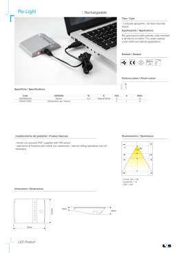
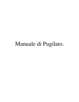
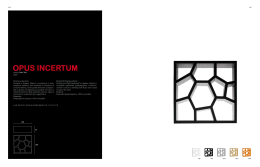
RAEE—WEEE N. 2002/96/CE N° 2003/108/CE Directiva Comunitaria -EU Directive—Directive communautaire— Gemeinschaftliche Richtlinie ITALIANO ”RAEE” - Gestione rifiuti apparecchiature elettriche ed elettroniche Il simbolo del bidone barrato posto sul prodotto o sulla documentazione del manuale d’uso, indica che il prodotto è stato immesso nel mercato dopo la data del 13 agosto 2005. Al termine del ciclo di vita utile, il prodotto, deve essere raccolto, smaltito, trasportato in modo separato rispetto agli altri rifiuti urbani seguendo le normative vigenti in ogni paese. In questo modo potrà essere recuperato contribuendo ad evitare possibili effetti negativi sull’ambiente e sulla salute, favorendo il reimpiego e/o il riciclo dei materiali di cui è composta l’apparecchiatura. Lo smaltimento abusivo del prodotto da parte dell’utente comporta l’applicazione di sanzioni amministratiuve previste dalla norma vigente. La Direttiva comunitaria “RAEE” N° 2002/96/CE, (in Italia recepita con il Dgls del 15.05.2005 N°151); Direttiva comunitaria N°2003/108/CE riguardante il trattamento dei rifiuiti delle apparecchiature elettriche ed elettroniche. ENGLISH “RAEE” - Electrical and Electronic Waste Management) The barred can symbol displayed on the product or in the use manual documentation indicates that the product has been placed for sale on the market after August 13, 2005. At the end of its useful life-cycle, the product must be collected, disposed of, and transported separately from urban waste, in accordance to the norms in force in each individual country. In this way, it can be recovered, contributing to avoid possible negative effects on the environment and health, and favoring the re-use and/or recycling of the materials of which the equipment is made of. The abusive disposal of the product by the user entails the application of administrative sanctions established by the norms in force. The EU Directive “RAEE” N. 2002/96/ CE, (implemented in Italy by the Law Decree n. 151 dated May 15, 2005); EU Directive N. 2003/108/CE concerning the handling of electrical and electronic waste. FRANCAIS ” RAEE” - Gestion des déchets d’appareillages électriques et électroniques Le symbole de la poubelle barrée placé sur le produit ou sur la documentation du manuel d’utilisation, indique que le produit a été mis sur le marché après la date du 13 août 2005. A la fin du cycle de vie utile, le produit doit être trié, éliminé, transporté de façon séparée par rapport aux autres déchets urbains en suivant les normatives en vigueur dans chaque pays. De cette façon, il pourra être récupéré en contribuant à éviter d’éventuels effets négatifs sur l’environnement et sur la santé, en favorisant le réemploi et/ou le recyclage des matériaux dont est composé l’appareillage. L’élimination abusive du produit de la part de l’utilisateur comporte l’application de sanctions administratives prévues par la normative en vigueur. La Directive communautaire “RAEE” N° 2002/96/CE, (en Italie définie dans le D. lég. du 15.05.2005 n°151); Directive communautaire N° 2003/108/CE concernant le traitement des déchets des appareillages électriques et électroniques. DEUTSCH RAEE” - Umgang mit Abfällen elektrischer und elektronischer Geräte Das Symbol der durchkreuzten Mülltonne auf dem Produkt oder der Dokumentation der Gebrauchsanweisung gibt an, dass das Produkt nach dem 13. August 2005 auf den Markt gebracht wurde. Am Ende des Nutzungszyklus muss das Produkt entsprechend der im jeweiligen Land geltenden Bestimmungen gesammelt, entsorgt und getrennt von anderem Hausmüll transportiert werden. Auf diese Weise kann es zurückgewonnen werden, wodurch zur Vermeidung möglicher negativer Auswirkungen auf die Umwelt und die Gesundheit beigetragen sowie die Wiederverwertung und das Recycling der Materialien erleichtert wird, aus denen das Gerät besteht. Die widerrechtliche Entsorgung des Produktes durch den Nutzer zieht die Anwendung der von den gültigen Bestimmungen vorgesehenen Verwaltungsstrafen nach sich. Die gemeinschaftliche Richtlinie “RAEE” Nr. 2002/96/EG, (in Italien mit der Gesetzesverordnung Nr. 151 vom 15.05.2005 umgesetzt); Gemeinschaftliche Richtlinie Nr. 2003/108/CE bezüglich der Behandlung von Abfällen elektrischer und elektronischer Geräte. 2 MANUALE D’USO E MANUTENZIONE DICHIARAZIONE DI CONFORMITA’ DECLARATION OF CONFORMITY DECLARATION DE CONFORMITE' KONFORMITÄTSERKLÄRUNG TIPO PRODOTTO - PRODUCT TYPE PRODUKTART - TYPAGE PRODUIT MODELLO - MODEL - MODĔLE - MODEL Vetrina refrigerata - Refrigerated display cabinet—Vitrine réfrigéré Kuehlvitrine—Vitrina refrigeraa VULCANO (SG-CG) .- L’azienda dichiara sotto la propria responsabilità che il prodotto sopraindicato soddisfa per progettazione e costruzione i requisiti della direttiva macchine .- The company declare under its own responsability that the above product meets for the design and the construction the requirements of the machines directive .- La société affirme sa propre responsabilité que le produit ci-dessus pour la conception et la construction répond aux exigences de la directive .- Die Firma erklärt unter alleiniger Verantwortung, dass das oben genannte Produkt die Gestaltung und Konstruktion den Anforderungen der Richtlinien erfüllt. -La empresa afirma de dice que su propia responsabilidad que el producto mencionado antes tiene el diseño y construcción que se ajusta a los requisitos de la Directivas de maquinas. DIRETTIVA BASSA TENSIONE- LOW VOLTAGE DIRECTIVE—DIRECTIVE BASSE TENSION NIEDERSPANNUNGS-RICHTLINIE—DIRECTIVA DE BAJO VOLTAJE DIRETTIVA COMPATIBILITÀ ELETTROMAGNETICA ELECTROMAGNETIC COMPATIBILITÀ DIRECTIVE COMPATIBILITÉ ÉLECTROMAGNÉTIQUE - ELEKTROMAGNETISCHE VERTRÄGLICHKEIT COMPATIBILIDAD ELECTROMAGNÉTICA 3 2006/95/CE 2004/108/CE MANUALE D’USO E MANUTENZIONE MURALE refrigerato Linea VULCANO mod. VULCANO 60 — VULCANO 80 INTRODUZIONE Gli apparecchi denominati murali refrigerati della “linea VULCANO” comprendenti i modelli “ VULCANO 60—VULCANO 80” sono stati realizzati rispettando l’insieme delle norme comunitarie riguardanti la libera circolazione di prodotti industraili e commerciali nei paesi UE. Prima di effettuare una qualsiasi operazione sul prodotto, si raccomanda di leggere attentamente il manuale d’uso e manutenzione. Inoltre, si sottolinea di seguire tutte le norme vigenti, anche quelle relative alla sicurezza (scarico-carico, installazione del prodotto, collegamenti elettrici, messa in funzione e/o smontaggio e spostamento / nuova locazione, smaltimento e/o riciclo del prodotto in oggetto). L’apparecchio deve essere utilizzato in accordo con quanto specificato nel presente manuale. L’azienda non si riterrà responsabile per rotture, incidenti o inconvenienti vari dovuti alla non osservanza e comunque alla non applicazione delle prescrizioni contenute nel presente manuale. Lo stesso dicasi per l’esecuzione di modifiche, l’esclusione delle sicurezze elettriche o lo smontaggio delle protezioni previste dal costruttore compromettono gravemente le condizioni di sicurezza, varianti, e/o installazioni di accessori non autorizzati od incuria ed in tutti casi in cui il difetto sia causato da fenomeni estranei al normale funzionamento del prodotto stesso (fenomeni atmosferici, fulmini, sovratensioni della rete elettrica, irregolare od insufficiente alimentazione elettrica...etc). La manutenzione comporta semplici operazioni eseguibili esclusivamente da un tecnico specializzato. USO DEL MANUALE Il manuale d’uso e manutenzione costituisce parte integrante del mobile e deve essere di facile ed immediata consultazione da parte degli operatori e/o tecnico qualificato e/o manutentore, per compiere, in modo corretto e sicuro, tutte le operazioni di installazione, messa in funzione, smontaggio e smaltimento dell’apparecchio. Questo manuale d’uso e manutenzione contiene tutte le informazioni necessarie per una buona gestione dell’impianto con particolare attenzione alla sicurezza. CONSERVAZIONE DEL MANUALE Il manuale d’uso e manutenzione deve essere conservato integro ed in luogo sicuro, protetto da umidità e fonti di calore, durante tutta la vita del prodotto, anche in caso di passaggio di proprietà ad altro utilizzatore in quanto contiene tutte le informazioni per un corretto smaltimento e/o riciclo dell’apparecchio. Deve essere conservato nelle immediate vicinanze dell’apparecchio in modo da renderne agevole la consultazione. Si raccomanda di utilizzare il manuale con cura in modo tale da non comprometterne il contenuto. Non asportare, strappare o riscrivere per alcun motivo parti del manuale. IL COSTRUTTORE SI RISERVA IL DIRITTO DI APPORTARE MODIFICHE TECNICHE AI PROPRI PRODOTTI SENZA PREAVVISO. 4 MANUALE D’USO E MANUTENZIONE DESCRIZIONE DEL BANCO Il manuale d'uso fa riferimento ad un mobile “MURALE REFRIGERATO” di tipo aperto o in versione “SELF-SERVICE” per la conservazione e la vendita di “prodotti preconfezionati “SALUMI e LATTICINI” e prodotti freschi “FRUTTA e VERDURA”. Il murale della linea VULCANO è prodotto in due differenti versioni: VULCANO mod. 600 profondità mm600 : “SALUMI e LATTICINI” base + n.4 ripiani con profondità 280mm cadauno VULCANO mod. 800 profondità mm760 : “SALUMI e LATTICINI” base + n.4 ripiani con profondità 380mm cadauno “FRUTTA e VERDURA” base + n.3 ripiani con specchio inclinato, profondità ripiano 380 mm cadauno Entrambi sono le versioni sono disponibili in acciaio INOX. Il mobile è fornito standard di illuminazione nella parte superiore, tenda notte manuale, controllore elettronico di comando, con gruppo incorporato oppure in versione per l’allacciamento ad unità condensatrice remota. Tensione di alimentazione standard 230V - 1 - 50Hz. La vasca è realizzata senza l'uso di CFC a basso impatto ambientale. Tutte le operazioni riguardanti i capitoli 1 - 2-3-4-5 e cioè : POSIZIONAMENTO del MOBILE FRIGORIFERO PULIZIA COLLEGAMENTO ELETTRICO e MESSA a TERRA MANUTENZIONE e SOSTITUZIONE di parti elettriche e frigorifere devono essere eseguite da un tecnico qualificato ed abilitato, ci si dovrà attenere alle normative di sicurezza ed a quelle elettriche vigenti. 5 MANUALE D’USO E MANUTENZIONE 1___POSIZIONAMENTO DEL MOBILE FRIGORIFERO Prima di scaricare/caricare e posizionare il mobile all'interno del locale di vendita, si prega di consultare attentamente il manuale nelle varie sezioni la riguardante lo scarico/carico del mobile, lunghezze, pesi, le posizioni di scarico acqua di condensa, la posizione dei piedini di regolazione e del quadro elettrico relativo al mobile in oggetto del presente nel manuale d'uso e di manutenzione del mobile. 1_1_____TRASPORTO NO Kg SI Kg Si raccomanda che il mobile frigorifero venga trasportato sempre e solo in posizione verticale. Se il banco frigorifero con unità condensatrice incorporata viene inclinato, si consiglia di attendere almeno due ore, prima di procedere all’avviamento. In questo modo, si permetterà all’olio di defluire in tutti i componenti in modo che essi né risultino lubrificati nuovamente; successivamente si potrà procedere all’avviamento. 1_2______SCARICO BANCO / LUNGHEZZE / PESI Kg Le operazioni di scarico/ carico del prodotto, devono essere eseguite da personale autorizzato ed abilitato. L’azienda declina ogni responsabilità per non aver seguito le norme di sicurezza vigenti in materia. Prima di iniziare le operazioni di scarico, posizionamento ed installazione del mobile frigorifero all'interno del punto di vendita, a seconda del tipo di modello di banco, consultare con attenzione i dati riportati nella tabella lunghezza, peso. 1_3_______IMBALLO Alla consegna verificare che l’imballo sia integro e che durante il trasporto non abbia subito danni. Togliere il nylon di imballo dal banco frigorifero comprese le barre fissate al telaio del banco frigorifero. Il recupero ed il riciclaggio dei materiali dell'imballo quali plastica, ferro, cartone, legno contribuisce al risparmio delle materie prime ed alla diminuzione dei rifiuti. Consultare gli indirizzi nella propria zona per lo smaltimento in discarica e centro autorizzato rifiuti. 1_4_______SCARICO ACQUA CONDENSA / TUBAZIONI GAS REFRIGERANTE Per lo scarico dell’acqua di condensa, si rimanda alle sezione relativa “VASCHETTA SCARICO ACQUA CONDENSA / COLLEGAMENTO SCARICO” con unità condensatrice incorporata (con vaschetta fissa scarico acqua di condensa) oppure nella versione con unità condensatrice remota, (mobile fornito di sifone di scarico acqua di condensa ma senza vaschetta di scarico acqua). Per le tubazioni gas refrigerante si rimanda al “sezione diametri tubazioni gas refrigerante”. 1_5_______POSIZIONAMENTO E REGOLAZIONE PIEDINI Sistemare il mobile frigorifero in posizione perfettamente orizzontale, agendo se necessario sulla regolazione dei piedini a vite delle gambe del banco per regolarne il livello verificare la planarità con una bolla. Il mobile deve essere posizionato perfettamente in piano per poter funzionare correttamente e permettere il corretto scarico dell'acqua di condensa dello sbrinamento, inoltre si evitano vibrazioni rumorose del motore. 1_6_______INSTALLAZIONE ALL'INTERNO DEL PUNTO DI VENDITA I banchi frigoriferi sono testati in sala climatica ad una temperatura ambiente +25°C ed umidità relativa ambiente 60%, pertanto se il punto di vendita ha condizioni climatiche diverse da quelle indicate, potrebbero verificarsi dei malfunzionamenti ed il banco frigorifero potrebbe non funzionare correttamente. (formazione di condensa….etc).L'area nella quale viene installato il mobile deve essere chiusa, evitando l'esposizione diretta ai raggi solari ed a tutte le altre forme di irraggiamento, quali illuminazione ad incandescenza ad alta intensità, forni di cottura, o corpi radianti tipo radiatori per riscaldamento. Inoltre, il banco frigorifero non dovrà essere posizionato vicino ad aperture verso l'esterno o a diretto contatto con il flussi d'aria provenienti da ventilatori, bocchette e fancoil per il condizionamento dell'aria. Verificare che nell'ambiente vi sia sufficiente ricambio d'aria, anche nei periodi di chiusura del locale di vendita. Se non installati nel parte posteriore del mobile murale, prevedere dei distanziatori in modo da avere una distanza di circa 5 cm tra la parte posteriore del mobile ed il muro. Questo permetterà un corretto ricircolo d'aria. 6 MANUALE D’USO E MANUTENZIONE 1_7_______VASCHETTA SCARICO ACQUA CONDENSA / COLLEGAMENTO SCARICO Il murale con unita condensatrice incorporata è dotato di serie di vaschetta fissa con ri-evaporazione tramite serpentina inox. Verificare che il tubo di scarico acqua sia posizionato in modo corretto e pulire periodicamente l'interno della vaschetta da residui o altro materiale. Per i mobili con unità remota viene fornito solo il sifone di scarico senza la vaschetta acqua di condensa. Sarà cura del cliente provvedere al collegamento per lo scarico dell’acqua. E’ importante che immediatamente fuori dalla vasca sia presente un sifone che blocchi la fuoriuscita dell'aria fredda e l'ingresso di odori inopportuni. Non si deve mai installare il banco senza sifone e nemmeno raccordare più scarichi dello stesso mobile, ogni scarico deve avere il suo sifone. 1_8_______BANCO CON UNITA' CONDENSATRICE INCORPORATA Se il banco frigorifero è dotato di unità condensatrice incorporata, bisogna evitare di ostruire le prese d'aria dell'unità in modo da non ostacolare il corretto ricambio d'aria. Evitare dunque di depositare prodotti o altri materiali sul perimetro del banco frigorifero. Ricordiamo che un innalzamento della temperatura ambiente o un'insufficiente quantità di aria al condensatore dell'unità frigorifera, riducono le prestazioni del banco frigorifero con possibile deterioramento dei prodotti esposti e con maggior consumo di energia. Se il banco frigorifero con unità condensatrice incorporato viene inclinato, si consiglia di attendere almeno due ore prima di procedere all’avviamento in modo che l’olio presente nel compressore defluisca al suo interno e tutti i suoi componenti né risultino lubrificati nuovamente, successivamente si potrà procedere all’avviamento. 1_9______BANCO CON UNITA' CONDENSATRICE in versione REMOTA Per quanto riguarda il collegamento elettrico si deve attenersi scrupolosamente alle normative elettriche vigenti in materia; si ricorda inoltre, che l'installazione elettrica e frigorifera deve essere effettuata esclusivamente da personale specializzato. Nel caso di banchi frigoriferi con unità condensatrice remota, il gruppo deve essere collocato al riparo degli agenti atmosferici, evitando di utilizzare il sito come deposito di materiali. A seconda delle caratteristiche del modello dell'unita condensatrice remota, si devono rispettare gli spazi dal muro o da altri ostacoli in modo che vi sia un ricambio d'aria sufficientemente adeguato che garantisce un corretto funzionamento del banco frigorifero e una facile manutenzione. 2___PULIZIA 2_1_______PULIZIA DEL BANCO FRIGORIFERO È' indispensabile tenere pulito giornalmente il banco frigorifero. Tutte le operazioni di pulizia devono essere eseguite con unità ferma, togliendo tensione sia al banco refrigerato che all'unità condensatrice. Non utilizzare acqua con getto per lavare le parti interne del mobile in quanto le parti elettriche potrebbero danneggiarsi. Non utilizzare attrezzi metallici duri per asportare il ghiaccio. Per la pulizia usare solo acqua tiepida con detersivi non aggressivi avendo poi cura di asciugare le parti umide con uno straccio morbido. Evitare di usare prodotti che contengono cloro e sue soluzioni diluite , soda caustica, detersivi abrasivi, acido muriatico, aceto, varechina o altri prodotti che possono graffiare o smerigliare. Un lavaggio settimanale è raccomandato per il fondo della vasca specialmente per i mobili soggetti a fuoriuscite di liquidi o di altri detriti di alimenti. Va fatta pulizia con detergente anche nelle zone esterne che circondano l'area espositiva: serve a mantenere il banco presentabile e previene la formazione di sporcizia. Fare attenzione, durante le operazioni di pulizia della vasca del banco frigorifero , una volta rimossi i piani di esposizione su cui è esposta la merce, bisogna porre attenzione a non ferirsi con le alette dell'evaporatore che, visto il loro spessore è ridotto sono taglienti; è consigliabile l'uso di guanti da lavoro. Attenzione non danneggiare e piegare le alette dell'evaporatore ed i tubi del fluido refrigerante. Fare attenzione anche ai contorni delle placche espositive. La manutenzione di un banco adibito alla conservazione di prodotti quali carne, salumi e latticini, deve includere almeno una pulizia periodica settimanale della zona di carico per prevenire lo sviluppo e l'accumulo di batteri. 2_2_______PULIZIA CONDENSATORE UNITA' CONDENSATRICE Tutte le operazioni di pulizia sia del banco frigorifero che del condensatore dell'unità condensatrice sono da eseguirsi con unità ferma, togliendo la tensione elettrica. Si raccomanda che tale pulizia venga effettuata da personale specializzato. Per poter contare sempre sul buon funzionamento dell'unità condensatrice è necessario eseguire periodicamente la pulizia del condensatore dell'unità condensatrice. Questa pulizia dipende principalmente dall'ambiente dove è installata l'unità condensatrice. Si consiglia di utilizzare un getto d'aria soffiando dall'interno verso l'esterno dell'unità; qualora non fosse possibile, utilizzare un pennello a setola lunga sull'esterno del condensatore. Attenzione a non danneggiare il circuito del fluido refrigerante. Per accedere al condensatore, svitare le viti frontali posizionate all'estremità del pannello frontale basso. Abbassare il pannello in modo da poter procedere alla pulizia del condensatore. Si consiglia di eseguire questa operazione di pulizia utilizzando guanti di lavoro Per poter contare sempre sul buon funzionamento dell'unità condensatrice è necessario eseguire almeno una volta al mese la pulizia del condensatore dell'unità condensatrice. Questa pulizia dipende principalmente dall'ambiente dove è installata l'unità condensatrice. 7 MANUALE D’USO E MANUTENZIONE 3_______COLLEGAMENTO ELETTRICO E MESSA A TERRA 3_1_____ALIMENTAZIONE ELETTRICA. L'installazione ed i collegamenti elettrici devono essere eseguiti a regola d’arte attenendosi alle norme elettriche vigenti in materia. Tali lavori saranno eseguiti da personale specializzato ed abilitato secondo le normative di legge vigenti. L’azienda declina ogni responsabilità derivante dall’inosservanza delle norme elettriche vigenti in materia. Vedere schema elettrico del mobile. Prima di collegare elettricamente il mobile eseguire una pulizia accurata e completa del banco frigorifero utilizzando acqua tiepida con detergenti neutri non aggressivi ed asciugando poi con uno straccio morbido tutte le parti umide (attenzione, leggere attentamente la sezione pulizia mobile). Per eseguire un corretto collegamento elettrico procedere come segue: Predisporre un interruttore magnetotermico differenziale ed accertarsi che la frequenza / tensione di linea corrisponda a quella indicata sulla targhetta di identificazione del banco frigorifero (vedere posizionamento targhetta) Verificare la tensione di alimentazione al punto di presa, sia quello nominale +-10% al momento dell'avviamento del compressore. Si consiglia di montare un interruttore unipolare di sezionamento con apertura dei contatti di almeno 3 mm, a monte della presa. Questo interruttore è obbligatorio quando il carico supera i 1000 Watt o quando il banco viene collegato direttamente senza l'impiego della spina. L’interruttore magnetotermico deve essere posto nelle immediate vicinanze del mobile in modo tale che esso possa essere ben visibile dal tecnico in caso di manutenzione. È necessario che la sezione del cavo di alimentazione sia adeguata alla potenza assorbita dal gruppo. È obbligatorio a termine di legge la messa a terra dell’impianto, pertanto è necessario collegarlo ad un efficiente impianto di messa a terra. Nel caso in cui il cavo di alimentazione sia danneggiato,esso deve essere sostituito da personale tecnico specializzato in modo da prevenire ogni rischio. Si raccomanda inoltre di non usare apparecchi elettrici all’ interno degli scomparti del mobile . Nel caso in cui il compressore sia danneggiato, questo deve essere sostituito esclusivamente da personale specializzato in modo da prevenire ogni rischio. Si consiglia, per evitare in caso di guasto di disinserire tutto l'impianto, di utilizzare come sezionatore un interruttore magnetotermico con differenziale da alta sensibilità. La spina elettrica del mobile frigorifero deve sempre essere collegata ad una presa fissa. È vietato collegare la spina elettrica del mobile ad una prolunga e/o o riduttore. 3_2______AVVIAMENTO DEL MOBILE Attenzione prima di effettuare l’avviamento, accertarsi : Di non avere le mani umide o bagnate Che le superfici del mobile frigorifero siano asciutte Che il pavimento sia asciutto Dopo aver fatto le verifiche sopra riportate, si potrà effettuare l’avviamento del mobile frigorifero. Prima di accendere il mobile frigorifero bisogna verificare che: il mobile frigorifero con unità condensatrice incorporata sia stato trasportato esclusivamente in posizione verticale, se fosse stato inclinato, si consiglia di aspettare almeno 2 ore prima di procedere all’avviamento in modo che l’olio presente nel compressore defluisca al suo interno e tutti i suoi componenti ne risultino lubrificati nuovamente. Per la regolazione dei parametri di funzionamento consultare le istruzioni d’uso del quadro elettronico di controllo allegate al presente manuale. Per mobili con gruppo incorporato, prima di inserire la spina nella presa di corrente elettrica, verificare che il sezionatore sia aperto in posizione 0, OFF o verde. Inserire la spina e quindi chiudere l'interruttore Evitare di impostare temperature inferiori a quelle relative alla categoria del mobile. Per mobili o gruppo remoto il primo avviamento deve essere effettuato da personale specializzato. Attenzione: prima di caricare la merce nel mobile, si deve attendere che la temperatura desiderata e impostata sul pannello di controllo sia raggiunta. .La migliore indicazione di funzionamento è data dalla temperatura indicata dal termometro posto nel banco. Le indicazioni fornite dalle scale graduate dei termostati possono discostarsi dalla temperatura del termometro e non possono perciò ritenersi valide per la verifica del buon funzionamento. 8 MANUALE D’USO E MANUTENZIONE 3_3_______FUNZIONAMENTO DEL MOBILE I mobili sono dotati di sistema automatico per lo sbrinamento periodico giornaliero già impostato in fabbrica secondo il fabbisogno riscontrato. In taluni casi può comunque verificarsi la necessità di effettuare uno sbrinamento manuale agendo sull'apposito comando, nel caso manchi questo tasto, si deve spegnere l'impianto di raffreddamento per il tempo necessario a far sciogliere tutto il ghiaccio presente nella serpentina (più di 40 minuti). Per una maggior risparmio energetico e un mantenimento migliore del prodotto, si consiglia l'impiego di coperchi o tende avvolgibili durante il periodo ci chiusura del negozio. 4 RACCOMANDAZIONI 4.1___________MAX CARICO PRODOTTO SU RIPIANO. Carico MAX uniformemente distribuito per ogni ripiano / vasca di kg 35 al metro lineare. 4.2___________CARICO DEL PRODOTTO Prima di caricare la merce nel banco frigorifero, attendere che la temperatura desiderata impostata dal termostato sia raggiunta dal banco frigorifero. Si ricorda che caricando del prodotto da raffreddare si peggiorano tutte le condizioni di funzionamento rischiando di danneggiare la merce già esposta. 4.3___________CONSERVAZIONE DEL PRODOTTO Si raccomanda di mantenere libere da ostruzioni tutte quelle aperture di ventilazione dell'aria di mandata e di ripresa all'interno del banco refrigerato. In special modo si deve evitare di posizionare il prodotto sulla griglia di ripresa dell’aria posizionata sulla parte frontale del mobile adiacente al piano di esposizione di base del murale. Nel caso di esposizione di prodotti di salumi affettati e in genere di formaggi stagionati è opportuno che questi non appoggino direttamente sul piano di esposizione ma su delle griglie che permettano la traspirazione della merce. In questo modo si evita che sul prodotto si formino delle zone bianche ed umide. I cassetti e gli sportelli dei banchi a servizio, le porte di armadi e di celle devono aprirsi solo per il tempo strettamente necessario per il carico e lo scarico dei prodotti in modo da evitare l'aumento della temperatura interna del banco e successivamente ad un ulteriore consumo di energia per riportare il prodotto alla temperatura iniziale di conservazione. Tenere le carni, anche durante il lavoro di sezionamento in sale refrigerate; quando le lavorazioni si prolungano per più di due ore riportare la merce nelle celle refrigerate. I banchi sono adatti all'esposizione di prodotto refrigerato che deve giungere ai magazzini ad una temperatura vicina a quella ideale di conservazione. La qualità della merce dipende anche da come è stata trattata prima dell'arrivo nei punti vendita. Perciò all'arrivo dei prodotti dal fornitore, è necessario metterli nei banchi o nelle celle frigo per evitare l'eccessiva perdita di freddo dovuta alla loro stazionamento in luoghi non refrigerati. Per il buon funzionamento del mobile è necessario che la disposizione del prodotto non ostacoli la circolazione dell'aria refrigerata. ATTENZIONE: > I bambini devono essere seguiti assicurandosi che non giochino con il mobile frigorifero. > Non conservare sostanze esplosive come lattine aeorsol con propellente infiammabile in questo apparecchio. 5_____MANUTENZIONE — RIPARAZIONE — SOSTITUZIONE Tutte le operazioni di manutenzioni, riparazioni e sostituzioni di componenti del banco frigorifero devono essere eseguite con unità ferma, togliendo tensione sia al banco stesso che all'unità condensatrice. Tali operazioni devono essere eseguite esclusivamente da personale abilitato e specializzato. Si consiglia di usare guanti da lavoro di protezione. Come ordinare le parti di ricambio Comunicare in modo chiaro ai nostri uff.commerciali: Modello del mobile frigorifero Numero di matricola del mobile frigorifero Descrizione e quantità della parte del ricambio eventualmente allegare una foto del particolare da ordinare. 5_1_______CONTROLLI PERIODICI A periodi regolari (almeno ogni 6 mesi), fare verificare da personale specializzato il perfetto funzionamento del sistema, si deve prestare attenzione e controllare e verificare come segue: l’impianto scarico dell’acqua di condensa funzioni correttamente Verificare che vaschetta acqua di condensa sia pulita al suo interno. Non vi siano perdite di gas refrigerante e che l’impianto refrigerante funzioni correttamente lo stato di manutenzione dell'impianto elettrico sia in completa sicurezza. Pulire il condensatore dell’unità refrigerante (la frequenza della pulizia dipende dall’ambiente in cui è installato il banco) lo stato di manutenzione dell'impianto elettrico sia in completa sicurezza. Corretto funzionamento delle resistenze di sbrinamento (se presenti) Corretto funzionamento dei motoventilatori (evaporatore, condensatore) 9 MANUALE D’USO E MANUTENZIONE 5_2_______SOSTITUZIONE LAMPADE ILLUMINAZIONE Le lampade da sostituire devono essere sostituite con altre di identica potenza. Verificarne i dati riportati sulla targhetta posta a lato della lampada. Tali dati definiscono la potenza assorbita dalla lampada. Per la sostituzione delle lampade posizionate sulla parte alta del banco frigorifero, staccare la spina di alimentazione o aprire il sezionatore posto a monte del collegamento del banco, togliere la protezione di plastica trasparente della lampada, prendere la lampada alle due estremità e ruotarla di 90° finchè si sente un leggero scatto, quindi estrarla facendo attenzione a non urtarla, manovrarla con cura evitando di romperla e di tagliarsi. Montare la nuova lampada inserendola e ruotandola come sopra e riposizionare la protezione trasparente. 5_3_______SOSTITUZIONE VETRO LATERALE spalla Nel caso di danneggiamento e/o sostituzione del vetro laterale lato spalla, recuperare il vetro evitando di disperderlo nell'ambiente. Si consiglia di usare guanti di protezione, fare attenzione, dopo la eventuale rottura del vetro, manovrare lo stesso con cura evitando di tagliarsi. 5_4_______SOSTITUZIONE MOTOVENTILATORE Nel caso di danneggiamento e/o sostituzione del motoventilatore, si necessita sostituirlo, togliere la tensione di alimentazione, verificare la targhetta dati tecnici del motoventilatore e sostituirlo con uno di identica potenza, voltaggio e frequenza. 5_5______SOSTITUZIONE COMPRESSORE / Gas refrigerante Nel caso di danneggiamento e/o sostituzione del compressore, recuperare il gas refrigerante e l’olio evitando di disperderlo nell'ambiente. 5_6_______PULIZIA CONDENSATORE UNITA’ CONDENSATRICE INCORPORATA Si rimanda al punto pulizia del condensatore, vedere pag 5. Per ulteriori spiegazioni vedere la sezione relativa alla pulizia del condensatore. 5_7_______BANCO CON SBRINAMENTO ELETTRICO Nei mobili dotati di sbrinamento elettrico attenzione a non scottarsi sulla resistenza elettrica che potrebbe risultare ancora calda. Aspettare quindi il suo raffreddamento e successivamente iniziare le operazioni di manutenzione. 5__8_____GESTIONE RIFIUTI — SMALTIMENTO MATERIALI Le apparecchiature elettriche ed elettroniche che compongono l’apparecchio, quali lampade, controllo elettronico, interruttori elettrici, motorini elettrici, compressori ed altro materiale elettrico in generale, devono essere smaltiti e/o riciclati separatamente rispetto ai rifiuti urbani secondo le procedure delle normative vigenti in materia in ogni paese. Inoltre tutti i materiali che costituiscono il prodotto quali: Lamiera, rame e alluminio, plastica e gomma, vetro, componenti in poliuretano schiumato ed altro. Gas ed olio refrigerante devono essere stoccati in appositi bidoni, non scaricarli nelle fognature. devono essere riciclati e/o smaltiti secondo le procedure delle normative vigenti in materia. Ricordiamo che lo smaltimento abusivo del prodotto da parte dell’utente comporta l’applicazione di sanzioni amministrative previste dalla norma vigente. Consultare gli indirizzi nella propria zona per lo smaltimento dei prodotti in discarica e/o centro autorizzato gestione e trattamento dei rifiuti. 10 MANUALE D’USO E MANUTENZIONE 11 USE AND MAINTENANCE MANUAL MULTIDECK COUNTER “VULCANO line” Model VULCANO 60 — VULCANO 80 INTRODUCTION The multideck-cabinets cabinets have been constructed in respect of the overall community norms concerning the free circulation of industrial and commercial products in EU countries,. With the goal of complying to the norms in force (even those related to safety issues), we recommend, before carrying out operations with the equipment, to pay special attention to the information reported in this manual, that is, the information concerning: loading-unloading, installation, electrical connections, start-up and/or dismantling (displacement and new positioning), disposal and/or recycling of the subject product. The appliance must be used according to the specifications of this manual. The disengagement of the electrical safety devices or the dismantling of the protections provided by the constructor seriously compromise the safety conditions mentioned above. Furthermore, these conditions are subject to compliance of installation instructions and power supply requirements for the unit, which must be strictly followed. Maintenance entails few and simple operations, which can be carried out solely by a qualified technician. USE OF THE MANUAL The use and maintenance manual is an integral part of the product and must be easily and readily available for consultation by the operator and the qualified technician and/or maintenance worker, in order for them to correctly and safely carry out all the installation, start-up, maintenance, dismantling, and disposal operations on the equipment. This user and maintenance manual contains all the information required for handling the unit with particular attention to safety. STORAGE OF THE MANUAL The use and maintenance manual must be stored integrally and in a safe place, protected from humidity and heat sources, during the entire life-cycle of the product, even in the case that its ownership is passed on to another user, since it contains all the information for the correct disposal and/or recycling of the product. It must be stored in proximity of the equipment, so that it can be readily consulted. We advise you to use the manual with care, so that its contents are not compromised. Under no circumstances shall the user remove, pull out or rewrite any parts of the manual. The company will not be held liable for any breakage, accidents or faults due to non-compliance, including non-compliance for not following the instructions of this manual. Moreover, the company will not be responsible if the user makes any modifications, variants or if non-authorised accessories are installed in the unit. THE MANUFACTURER RESERVES THE RIGHT TO MAKE TECHNICAL MODIFICATIONS TO ITS OWN PRODUCTS WITHOUT GIVING PRIOR NOTICE. EN 12 USE AND MAINTENANCE MANUAL CABINET'S DESCRIPTION The use manual referring to the "SELF-SERVICE REFRIGERATED MULTIDECK CABINET" for display of “pre-packet Milk and Dairies products” , fresh Fruit and Vegetable. The VULCANO line is producing in two different version: VULCANO model 600 with depth 600mm : “DAIRIES version” with base + n.4 shelves with depth 280mm each VULCANO model 800 with dept 760mm : “DAIRIES version” with base + n.4 shelves with depth 380mm each “FRUIT & VEGETABLE version” with base + n.3 inclined shelves with dept 380mm VULCANO versions are also available in INOX version. The cabinet is supplied standard with lighting on the top, manual night curtain, electronic control panel, with built-in unit or predisposed for connection to the remote condensing unit. Power supply 230V - 1ph - 50Hz. The belly section is done with CFC-free with low environmental impact. All operations regarding the points 1-2-3-4-5 “ : Cabinet’s positioning Cleaning Electrical and hearthing connections Maintenance and replace of electrical and/ or cooling parts must be done by qualified technician and following the safety and electrical norms in each country. EN 13 USE AND MAINTENANCE MANUAL 1_______CABINET’S POSITIONING Before to unload/download and positioning the cabinet inside the sale-area, please read with attention the USE MANUAL on the sections regarding unload/download of the cabinet, length, weight, water pipe drain position, levelling and feet position and electronic control panel position. 1_1______TRANSPORTATION NO Kg YES Kg In order to avoid any damage to the compressor, we recommendto transport the cabinet only is vertical position. If the cabinet with built-in condensing unit is sloped transported, we suggest to wait at least 2 hours before to proceed with the start-up. In this way, the oil will lubrificate every part of the compressor, after which you could proceed to the start-up of the cabinet. 1_2_______DOWNLOAD - UNLOAD / LENGTH / WEIGHTS Unloading / loading of the product, must be performed by authorized personnel and authorized personnel. The company disclaims any responsibility for failing to follow safety rules in force. Kg Before to start all the operation of unload of the cabinet from the truck or container and positioninginstallation of the refrigerated display cabinet inside the sale-area, please read with attention the technical data reporting on the USE MANUAL on table length, weight of the cabinet, after that you can start the all operations of unloading. 1_3_______PACKING Upon delivery to verify that the packaging is intact and that during transport has not been damaged. When the counter has been positioned in the right place, take the packaging off, the bars fixed at the legs, too. The recovering and recycling of packing materials as plastic, iron, cartoon and wood in order to contribute to save the feedstock and to reduce the garbage. We suggest to consult the addresses in your area for the correct dispatch in the dumping ground and garbage authorized centre. 1_4_______WATER CONDENSATION DRAIN / GAS REFRIGERATING CONNECTION PIPES For water drain, see the section “WATER CONDENSATION DRAIN / WATER DRAIN CONNECTION”, with counter with builtin unit (the water condensation drain tanks is not removable). The cabinet with remote unit version is fitted with water drain siphon only and without water drain tank.. Regarding gas refrigerated connection pipes see the “section gas refrigerating diameter pipes”. 1_5_______LEVELLING and FEET REGULATION Move the appliance into its final position and adjust the screw-type feet until you have the unit perfectly level. The cabinet must be positioning in a perfect horizontal position, setting the desired level by turning the feet and checking if it is in line with the floor, if necessary make the adjustment to the feet of the cabinet . Pay attention and checking the planarity with the instrument. All these operation on installation will allow the cabinet to operate correctly with a good drainage of the water coming from the defrosting time process and the absence of noisy vibrations. 1_6_______INSTALLATION INSIDE THE BUILDING The cabinets are testing in test-room with ambient temperature of +25°C and relative humidity 60%, therefore, if the ambient in which the cabinet is installed has different conditions of ambient temperature and relative humidity, it could be verified a malfunction and the cabinet will not run properly (making inside condensation….etc). The room in which the counter is placed must be closed and must be sufficiently aired, even when the shop is closed and avoiding direct exposition of the counter to sun rays and to any other source of incandescence at high intensity, ovens, radiators or radiators of central heating. Furthermore, the cabinet cannot be positioned near any openings, as doors, windows…etc, or better in direct contact with air flow coming from fans or air conditioning systems. Avoid to obstruct the sources of air placing objects along the perimeter of the counter. It is necessary to place cabinets at least five centimetres from the wall. (do not remove the black spacers or headstocks) on EN the back of the cabinet, they be use to guarantee a good air circulation between the cabinet and the wall. 14 USE AND MAINTENANCE MANUAL 1_7_______WATER CONDENSATION DRAIN / WATER DRAIN CONNECTION The cabinet with built-in unit is fitted with automatic evaporating water condensation tank with stainless steel cooling (tank not removable). Verified that the water pipe is correct positioned and periodically and the basin is must be cleaned from waste materials. The counter with remote unit, not having the basin for water collection is provided with a siphon only, the customer take care of the water connection pipe. Its connection to the principal basin prevents the circulation of cold air and of bad smells. The counter cannot absolutely be installed without siphon and each drain must have its own siphon. It is necessary to have the drain-siphon after the exit of belly section to block the out-take air and also to avoid any smell. You never install the cabinet without siphon and to connect more drains of the same cabinet together. Each drain must have only one siphon. 1_8_______COUNTER WITH BUILT- IN UNIT If the cabinet is fitted with built-in condensing unit, check if the foot board obstructs air circulation. Do not put any cartoons or any others materials and do not close the air in-take and out-take on all sides of the cabinets. For a good running and performance of the cabinet, do not obstruct the condensing unit ventilation. Air suction grid and air delivery grid positioned on the front and back sides of the cabinet must be always opening. Check if the room is sufficiently aired, even when the shop is closed. Avoid to obstruct the sources of air placing objects along the perimeter of the counter. It is necessary to place cabinets at least five centimetres from the wall. Check if the foot board obstructs air circulation. Before activating electric connection clean the counter completely by using tepid water and neutral detergents (non–aggressive) . Dry it with a smooth rag. 1_9_______COUNTER WITH REMOTE CONDENSING UNIT version The electrical and cooling connection must be done only from a qualified technician. We recommend to follow the electrical norm The engine of counters with remote refrigerating unit must be protected from atmospheric agents and the room must not be used for storing goods (free space all around the remote unit). Respect the spaces between the unit and the walls or others obstacles, in order to have a good air exchange to avoid a good performance and easy maintenance during the cleaning of the condensing unit. It is necessary to remember that higher room temperature and insufficient air circulation around the condensing unit imply higher energy costs and worse technical performances of the refrigerator, with a possible waste of the exposed goods. 2_______CLEANING 2_1_______CLEANING OF MULTIDECK cabinet The refrigerated multideck cabinet must be kept clean daily. All cleaning operations must be carried out with the refrigerated table in stop position; the multideck cabinet as well as the built-in refrigeration unit must be completely powered off. Warning: it is advisable to use gloves when cleaning the multideck cabinet. Avoid using products that contain chlorine or its diluted substances, as well as sodium hydroxide, abrasive detergents, muriatic acid, vinegar, bleach or other products that may scratch or scrape the surface of the unit. Never use high-pressure water jet to wash internal parts of the mulktideck cabinet as electrical parts could be damaged. Do not use heavy metal devices to remove ice. Only use warm water with non-aggressive detergents to clean the refrigerated table; make sure to dry all wet parts using a soft cloth. It is advisable to wash the bottom of the basin on a weekly basis, especially parts that are exposed to discharge of liquids or other food waste. The external parts of the multideck cabinet that surround the display area must also be cleaned using cleansing agents: this will help keep the multideck cabinet presentable free of encrustations. Warning: do not damage or bend the evaporator’s flaps or refrigerant fluid pipes. In order to avoid bacteria formation, the loading zone of the refrigerated table used for preserving food products such are meat, salami or dairy products, must be cleaned at least once a week. 2_2_______CONDENSER’S BUILT-IN UNIT CLEANING Any operation of cleaning must be done disconnecting the electric power supply. The condenser of the cabinet with built-in unit must be cleaned, in normal conditions of use of the counter, at least once a month by using a vacuum cleaner and a real-bristle brush. It is advisable to use gloves since the reduced thickness of the wings can cut. Dirty condensing unit reduce the output oft he engine causing an increase of energy consumption. Take care not to damage the refrigerating fluid circuit. To access to the condenser, unscrew the two screws positionig to the extremity part of the low front panel of the multi deck. Open the front panel, positione don the floo, paying attention to the electronic control board at your right side. The condenser features sharp edges. Wear protective gloves when cleaning. In order to ensure good operating performance, the condenser unit must be cleaned on a regular basis at least once at month. 15 EN USE AND MAINTENANCE MANUAL 3_____ELECTRICAL POWER SUPPLY AND HEARTHING CONNECTION 3_1_____ELECTRICAL POWER SUPPLY The electrical installation and the connections must be done only from a qualified technician following the Electrical norms. The manufacturer declines every responsibilities consequently for do not observed to the specification of the electrical norms. See electrical diagram. Before to connect electrically the cabinet cleaning it completely used tepid water with neutral detergent. They must be not aggressive chemical formula. Once you have finished cleaning, dry with a soft, dry cloth (do not wash the appliance with jets of water. Do not use scouring pastes or stel wood (read with attention the point 2— CLEANING). In order to make the correct electric connection, proceed as follows: Fit a differential magneto-thermal switch and verified that the frequency / tension of the line must correspond to those written on the identification label of the counter (see the point IDENTIFICATION LABLE OF THE CABINET ). At the start-up compressor verified the value of nominal tension is +-10% of the value. It is advisable to install an onnipolar sectioning switch with opening of contacts at least 3 mm wide at the source. This switch is necessary when the charge is higher than 1000 Watt or when the counter is connected directly without using a plug. The magneto-thermal switch must be placed immediately next to the counter so as to be easily seen by a technician in case of maintenance. It is necessary that the section of the power supply cable is suitable to the power absorbed by the unit. The law requires that the unit is earthed; therefore it is necessary to connect it to an efficient earthing connection. In order to prevent any risks if the electrical cable and the compressor supplied are damage, these must be replaced by qualified technician. Installation must be carried out only by qualified technicians according to the regulation in force. No liability whatsoever can be accepted if the above instructions in not complied with. It is furthermore recommended not to use electrical equipments inside the counter. In order to avoid stopping the whole plant, in the case of troubles, use a magneto-thermal switch with a high sensitivity differential as a sectioning unit. 3_2_______CABINET’S START- UP Before to proceed to the switch-ON of the cabinet you have to verify as follow: The cabinet with built-in unit had been transported in vertical position, if it should be sloped, we suggest to wait at least 2 hours before to proceed with the start-up. In this way, the oil will lubrificate every part of the compressor, after which you could proceed with the start-up of the cabinet. To regulate and setting the working parameters, check the instructions on the control panel. The cabinet with built-in unit, before connecting the counter provided to the plug, check if the sectioning unit is in the position marked by “0,” “OFF” or “GREEN.” Connect the socket to the plug and close the switch. Avoid to set a lower temperature than that suggested according to the category the counter belong to. Attention: before exposing the goods, wait that the temperature set on the electronic control be achieved. This will bring no benefits, but the blocking of the evaporating unit. The good working of the counter is suggested by the temperature shown by the thermometer within the counter. The data reported by the thermometer scales can differ from the temperature reported on the thermometer and thus they cannot be considered valid for checking the good working of the counter. EN 16 USE AND MAINTENANCE MANUAL 3_3_______RUNNING OF THE CABINET The counters are provided with an automatic system for daily defrosting already set by the manufacturer in according to the necessity. Sometimes it can be necessary to practice a manual defrosting by using the provided button. In the case it lacks, switch the counter off for the time necessary to let ice melt on the serpentine (more than 40 minutes). It is furthermore recommended not to use mechanical or other devices to accelerate the defrosting process. It is advisable to cover counters with curtains during the night or the periods of non-working to preserve food better and avoid waste of energy. 4_______RECCOMENDATIONs and ADVICES 4_1_____Max shelf LOAD The MAX uniformed distribuited load of each shelf and belly is 35 kg for linear meter. 4.2_____Food merchandising The refrigerated food should be introduced for exposition in the counter at a temperature next to that necessary to its preservation. The quality of food depends on the kind of treatment had before its exposition 4.3_____Reccomandations and advices The exposition of food must not obstruct air suction / delivery circulation They respect some adequate proportions which permit air circulation. Also avoid to obstruct the passage of the air which is on the front of the counter. It is important, for example, not to obstruct the grid by attaching price stickers. It is highly recommended to keep all ventilation outlets clear within the counter. In the case of the exposition of seasoned sausages or cheese it is better if they do not lay directly on the exposition top but on grids which let the products transpire. This will prevent the formation of mould. The drawers and doors of the counters and the doors of the refrigerated cupboards and cold rooms must be opened only for the time necessary to take products out or introduce them. This will prevent the dispersion of cold. It is important to preserve meat in cold rooms also during the period of cutting. When the cutting of meat takes more than two hours refrigerate it again in the cold-room. Deep-frozen products should not have a temperature higher than –18° C. The introduction of non-refrigerated food can damage the general working of the counter, risking also wasting the exposed products. Thus, it is extremely necessary to preserve food in cold rooms or counters before exposing it. WARNING: > Children must be monitored closely to make sure they do not play with the appliance. > Do not store explosive substances such as aeorsol cans with flammable propellant in this appliance 5_______MAINTENANCE OF THE COUNTER In order to prevent any risks, before to start any operation of maintenance, repairing and cleaning you always must to disconnect the electric power supply, (must be switch-off) from the multi -deck and the condensing unit. All these kind of operation must be done by a qualified technician. Wear protective gloves when cleaning. 5_1_______PERIODIC CHECKS The unit must be checked six-monthly by qualified staff in order to verify the correct operation of the system; the following must be verified: the condensed water drainage system must work correctly check that condensed water tank is clean inside. check for gas refrigerant leaks and make sure the refrigeration unit works correctly make sure the condition of the electric system is completely safe clean the condenser of the refrigeration unit (the frequency of cleaning depends on where you installed the counter). EN 17 USE AND MAINTENANCE MANUAL 5_2_______REPLACE OF TOP CANOPY LIGHT The fluorescent lamps, include the information that the lamps have to be replace by identical lamps only. See the max lamps power identification label near the lamps. The electric power supply must be switch-off, by disconnecting the counter or by opening the switch You find at the top of principal electric supplier whenever it is necessary to change the lamps. To remove the lamp take the plastic protection of the lamp off and size it at the two ends. Move it 90° round till You hear a click. Replace the lamp paying attention not to break it. Install the new lamp following the same instructions and cover it again with the protection. 5_3_______SIDE WALL GLASS’S REPLACE In case the side glass end wall damage and/or side glass end wall replace operation, remember to do not dissipate on the environment. 5_4_______DAMAGE or REPLACE : COMPRESSOR / GAS REFRIGERANT and OIL (**) In case of damage or replace of compressor unit, remember to recover the gas refrigerant do not dissipate on the environment. 5_5_______BUILT-IN UNIT : CONDENSER’S CLEANING For explanation and pictures see the section CLEANING. 5_6_______ELECTRIC DEFROST CABINET On cabinet with electric defrost, pay attention do not burn himself by the electric defrost heater . 5_7_____WASTE MANAGEMENT — DISPOSAL OF MATERIALS Electrical and electronic equipment such as lamps, electronic controls, electrical switches, electrical motors, compressors and, in general, any other electrical material, must be disposed of and/or recycled separately from urban wastes, in accordance to the procedures indicated by the norms concerning the subject, in force in each country. Furthermore, all the materials that make up the product, such as: steel sheets, copper, and aluminum, plastic and rubber, glass, foamed polyurethane components, and the like; refrigerant gas or refrigerant oil must be stocked in appropriate cans, and not discharged into the sew- age system; must be recycled and/or disposed of in accordance to the procedures indicated by the norms in force concerning the subject. Please be reminded that the abusive disposal of the product by the user entails the application of administrative sanctions established by the norms in force. Check the address locations in your area of the disposal site and/or the authorized agement and handling of waste, to correctly dispose of the product. centers for the man- EN 18 USE AND MAINTENANCE MANUAL 19 MANUALE D’USO-USE MANUAL- MANUEL D’UTILIZATION - BEDIENUNGSANLEITUNG Murale self-service refrigerato per la vendita di prodotti SALUMI e LATTICINI, FRUTTA e VERDURA e BIBITE. Versione non canalizzabile. Serve-over refrigerated display cabinet for Dairy and milk product, Fruit and Vegetable beverages. Version cabinet not multiplexable 600 600 760 760 760 SL 400 SL VULCANO mod. Murale Multideck Mueble 2020 380 2020 1970 290 530 530 FV 600 Lunghezza con spalle (sp. 40 mm cad) 760 Peso con imballo Length included end walls thickness (mm 40 each) Longueur joues compris (épaisseur joue 40 mm ) Weight with packing Poids en total (déjà emballé) Länge (inkl. Seitenteile) (Seitenteil: Isolierstärke: 40mm) Gesamtgewicht (mit Verpackung) Versione mm Kg 60 680 100 / 80 880 120 / 100 1080 140 180 125 1330 170 210 140 1480 200 225 150 1580 225 240 187 1955 255 280 200 2080 / 300 225 2330 / 350 250 2580 / 400 280 2830 / 450 300 3080 / 500 Mural 20 MANUALE D’USO-USE MANUAL- MANUEL D’UTILIZATION - BEDIENUNGSANLEITUNG Lunghezza con spalle (sp. 40 mm cad) - Length included end walls thickness (mm 40 each) Longueur joues compris (épaisseur joue 40 mm ) - Länge (inkl. Seitenteile) (Seitenteil: Isolierstärke: 40 mm) VULCANO 600 VULCANO 800 1080 600 760 800 760 1000 1330 1500 1955 1250 1480 1400 1580 760 600 1080 600 1250 1480 760 600 880 600 1000 1330 1875 2080 1400 1580 760 600 760 680 2000 1500 760 600 2330 2250 1955 760 2500 2830 760 1875 2750 3080 760 600 2580 21 3000 MANUALE D’USO-USE MANUAL- MANUEL D’UTILIZATION - BEDIENUNGSANLEITUNG 1 2 VULCANO 3 6 5 4 100V-CG 7 8 9 15 10 11 12 13 14 Targhetta identificazione mobile frigorifero Tale targhetta è posizionata all'interno del mobile nella parte alta a sinistra sulla spalla interna. Essa definisce tutti i dati tecnici del mobile frigorifero come da legenda sotto riportata. Identification label of the cabinet The label of the cabinet is positioned inside on the internal part of the cabinet on the left side of the end wall. It defined all technical data of the multi-deck cabinet as showed on the table down written Etiquette d’identification du murale L’étiquette est positionnée dans l’intérieur de la vitrine réfrigérée (joue interne) sur la partie haute, à gauche. Elle définit toutes les dates techniques sur la vitrine, selon la tabelle ci-dessous. Das Typenschild des Kabinetts Kühlschrank Die Platte definiert die technischen Daten der mobilen Kühlschrank Legende 22 MANUALE D’USO-USE MANUAL- MANUEL D’UTILIZATION - BEDIENUNGSANLEITUNG LEGENDA / LEGEND I 1 Numero matricola Data di 2 produzione 3 Modello Tipo di 4 versione Tipo gas 5 refrigerante Norma 6(*) sicurezza Tipo gas di 7 espansione 8 9 EN Serial number F Date of production Model Version type Refrigerant gas type Safety Norm Expansion gas type Carica gas (grammi) Potenza elettrica illuminazione (Watt) DE Numéro matricule Date de fabrication Modele Type de version Gas de réfrigerant Matrikelnumber Zeitpunkt der herstellung Modell Typ version Gas als Kaeltemittel Norme de sécurité Gas de expansion Charge de gas Charge of gas Top lighting total electrical power Gas-Erweiterung Gas-Kosten Puissance total de la lumière Elektrische Leistung von licht Résistace eau Condensat Resistenz gegen WasserKondensation 10 Resistenza acqua di condensa (Watt) Electric heater condensation water 11 Resist sbrinamento elettrico(Watt) Résistance Electric defrost he- dégivrage ater Électrique 12 Rechtsvorschriften Widerstand Abtauung Elektrische Total input power Consommation electrique totale Total Stromverbrauch Power supply Tension d’alimentation Spannung 13 Pot. assorbita totale (A) Tensione alimentazione (Volt) 14 N° Fasi N° Phases N° phase Phasen 15 Frequenza (Hz) Frequency Fréquence Frequenz Safety norms Norme sicurezza EN 60335 – 2—89 IEC60335 — 2—89 Climatic class Classe climatica Max Ambient temperature Max temp. Ambiente 3 5 +32°C +43°C 23 MANUALE D’USO-USE MANUAL- MANUEL D’UTILIZATION - BEDIENUNGSANLEITUNG 9 1 8 2 7 6 3 4 5 LEGENDA / LEGEND 1 I Spalla laterale GB Side end wall F Joue DE Seitenwand 2 Vetro laterale spalla Side glass Vitre lateral Seitenglas 3 Piedino regolazione Regulation feet Regulation du pied Verstellbaren Fuß 4 (*) Pannello frontale apribile Opening front panel Panneau frontal qu'on peut Aufklapparen unteren Paneel ouvrir 5 Quadro elettronico Electronic control panel Panneau de comande éElektronisches Steuerpaneel lectronique 6 7 Pannello inferiore Ripiano Front panel Shelf Frontal inférieur etager Untere Blende Ablage 8 Tenda notte manuale Manual night curtain Rideau de nuit manuel Hand-Nachtrollo 9 Pannello superiore Top panel frontal supérieur Obere Blende 10 Unità condensatrice Built-in condensing unit Groupe logé Aggregat 11 Ventola condensat. Condenser fan Ventilateur du condensateur Lufterrad-Kondensator 12 Condensatore ad aria Air condenser Condensateur à air Luftkondesator 13 Vaschetta condensa Water condensation tank Bac de condensation de l'eau Wasserschale für Kondenswasser 14 Serpentina inox Inox pipe Serpentine en acier Edelstahlserpentine Nota—Note (*) Solo per la manutenzione — For maintenance olnly. 24 MANUALE D’USO-USE MANUAL- MANUEL D’UTILIZATION - BEDIENUNGSANLEITUNG Parte anteriore particolare condensatore ad aria — Front view particolar of air condenser — Partie antérieur particulier du condensateur à air—Details vorderen paneels — Parte anterior: particular del condensador a aire B A 12 Facile pulizia: facile rimozione del pannello frontale per accedere alle parti interne. Questo permette una facile pulizia del condensatore. 10 11 Easy clearing system: easy removal of frontal panel to access to the tecnica components. This allow an easy claening of the condenser.the technical components. This allow an easy cleaning Facile levée de panneau frontale pour accés aux composants technique, ce qui permet un facile netooyage du condensateur. 13 14 Einfache sauberung: Das vordere paneel ist leicht abzunehmen fur eine einfache und schnelle Reinigung des Kondensators und der interne Teile. Parte posteriore murale — Multideck back side Partie postérieur du mural — Parte posteriore del mural PULIZIA CONDENSATORE .- Svitare le due viti (A-B) poste all'estremità del pannello frontale del murale .- Aprire il pannello ed adagiarlo a terra facendo attenzione al quadro elettronico posto alla vostra destra. Per la pulizia condensatore, leggere il manuale d'uso al punto pulizia e manutenzione condensatore. CONDENSER CLEANING .- Unscrew the two screws (A-B) positionig to the extremity part of the low front panel of the multideck .- Open the front panel and pay attention to the electronic control borad at your right side. For cleaning the condenser, please read the note on the USE manual at Condenser cleaning. NETTOYAGE DU CONDENSATEUR .- Retirez les deux vis (AB) placé à la fin de la face avant de la murale .- Ouvrez le panneau et l'étendre sur le sol en veillant à placer l'image électronique à votre droite. Pour nettoyer le condenseur, lisez le nettoyage manuel et d'entretien pour le condensateur point. REINIGUNG CONDENSER .- Die beiden Schrauben (AB) platziert am Ende der Frontplatte des Wandbildes .- Öffnen Sie die Systemsteuerung und lege sie auf den Boden dafür, dass die elektronische Bild auf der rechten Ort. Um den Kondensator sauber, lesen Sie die manuelle Reinigung und Wartung auf den Punkt Kondensator. 25 MANUALE D’USO-USE MANUAL- MANUEL D’UTILIZATION - BEDIENUNGSANLEITUNG VULCANO 60 - Dati e caratteristiche di impiego / Technical Datas and operational features / Technisce Daten und Eingeschaften / Dates et caractèristiques do foncion / Datos y caracteristicas de uso Tensione di alimentazione Volt 230 - 50Hz ; Condizioni di funzionamento classe climatica 3 (+25° C temperatura ambiente 60 % umidità relativa) Temperatura di funzionamento SALUMI e LATTICINI (+3+5C).Sbrinamento a fermata Tension Volt 230 - 50Hz ; Working conditions: Climatic class 3 (+25° C ambient temperature; 60 % R.H) Running temperature DAIRY (+3+5°C). Simple defrosting. Tension de fonction en Volt 230 - 50Hz; Condition de fonctionnement classe 3 (+25° C température ambiante, humidité rélative à 60%) Température de fonction CHARCUTERIE / PRODUITS LAITIERES (+3+5°C) Simple dégivrage Spannung:230V/50 HZ, Betriebsbedingungen : Klimatische Klasse 3: (Raumtemp. +25°C, 60% R.F.) Minimale Betriebstemperatur für alle Versionen in Bezug DELIKATESSEN (+3+5°C). Einfache Abtauen Tension de uso en Volt 230 - 50Hz ; Condiciones de funcionamiento clase 3 (+25° C temperatura ambiente 60 % humedad relativa) Temperatura dè ejercicio CHARCUTERIA/LACTEOS (+3+5°C) Desescarchamiento simple. Mod. VULCANO 60 Versione - Version Salumi — Dairies 60 80 100 125 140 150 187 7,1 7,9 7,9 7,9 8,0 8,0 13,3 1x36 1x36 1x36 1x58 1x58 1x58 Potenza totale assorbita gruppo incorporato e Ventilatori Total electrical power INPUT built-in unit and fans/ Puissance Absorbeè total de groupe logé e ventilateur / Leistungsaufnahme (Mit Aggregat and Lufterrad) Potenza totale assorbita illuminazione / Total power consumption by lighting / Puissance absorbé de la lumière /Leistungsaufnahme der Beleuchtung (ohne Zubehör) / Superficie esposizione - Display surface - Surface d'exposition standard - Superficie de exposicion - Auslagefläche A N°-W 1x18 m2 0,93 1,25 1,57 1,95 2,19 2,35 2,94 Lunghezza con spalle (sp. 40 mm cad) - Length included end walls thickness (mm 40 each) - Longueur (joues compris) ( épaisseur joue 40 mm ) Länge (inkl. Seitenteile) (Seitenteil: Isolierstärke: 40 mm) - mm 680 880 1080 1330 1480 1580 1955 Peso totale con imballo -Total weight with packing -Poids en total (déjà emballé) - Gesamtgewicht (mit Verpackung) - Kg 100 120 140 170 200 225 255 26 MANUALE D’USO-USE MANUAL- MANUEL D’UTILIZATION - BEDIENUNGSANLEITUNG VULCANO 80 - Dati e caratteristiche di impiego / Technical Datas and operational features / Technisce Daten und Eingeschaften / Dates et caractèristiques do foncion Tensione di alimentazione Volt 230 - 50Hz ; Condizioni di funzionamento classe climatica 3 (+25° C temperatura ambiente 60 % umidità relativa) Temperatura di funzionamento SALUMI e LATTICINI (+3+5°C). - FRUTTA e VERDURA (+6+8°C) Sbrinamento a fermata Tension Volt 230 - 50Hz ; Working conditions: Climatic class 3 (+25° C ambient temperature; 60 % R.H) Running temperature for DAIRY (+3+5°C) and FRUIT & VEGETABLE (+6+8°C) Simple defrosting. Tension de fonction en Volt 230 - 50Hz; Condition de fonctionnement classe 3 (+25° C température ambiante, humidité rélative à 60%) Température de fonction CHARCUTERIE / PRODUITS LAITIERES (+3+5°C) FRUIT - Légumes Simple dégivrage Spannung:230V/50 HZ, Betriebsbedingungen : Klimatische Klasse 3: (Raumtemp. +25°C, 60% R.F.) Minimale Betriebstemperatur für alle Versionen in Bezug DELIKATESSEN (+3+5°C) / OBST UND GEMÜSE (+6+8°C) Einfache Abtauen. Tension de uso en Volt 230 - 50Hz ; Condiciones de funcionamiento clase 3 (+25° C temperatura ambiente 60 % humedad relativa) Temperatura dè ejercicio CHARCUTERIA/LACTEOS (+6+8°C) FRUTA Y VERDURA (+6+8°C) Desescarchamiento simple. Mod.VULCANO 80 Versione - Version Salumi—Frutta Dairies- 100 125 140 150 187 200 225 250 275 300 Fruit&Vegetable Potenza totale assorbita gruppo incorporato e Ventilatori - Total electrical power INPUT built-in unit and fans/ Puissance Absorbeè total de groupe logé e ventilateur / Leistungsaufnahme (Mit Aggregat and Lufterrad) A 7,3 7,9 7,9 8,0 13,3 2x 8A cad. 13,4 13,5 13,5 13,5 / each Potenza totale assorbita illuminazione / Total power consumption by lighting / Puissance absorbé de la lumière /Leistungsaufnahme der Beleuchtung (ohne Zubehör) N°1x18 1x18 1x18 1x36 1x58 2x36 2x36 2x36 2x36 2x36 W Superficie esposizione - Display surface - Surface d'exposition standard - Superficie de exposicion - Auslagefläche m2 Lunghezza con spalle (sp.40 mm cad) Length included end walls thickness (mm 40 each) - Longueur (joues compris) (épaisseur joue 40 mm ) -Länge (inkl. Seitenteile) (Seitenteil: Isolierstärke:40mm ) mm 1080 1330 1480 1580 1950 2080 2330 2580 2830 3080 Peso totale con imballo -Total weight with packing -Poids en total (déjà emballé) - Gesamtgewicht (mit Verpackung) - Kg 180 2,1 2,6 210 2,9 225 27 3,1 240 3,9 280 4,1 300 4,6 350 5,2 400 5,7 6,2 450 500 28 L N USCITA OUT L N Data - Dated 1 25.7.12 3 A ELSPEED SA12 Product 6 SPEED 5 RC 1 8 Prodotto R1 Eliwell Disegno - Drawing N° Modello 4 B 2 10 9 8 7 6 5 4 3 2 1 SL - FV DAIRIES-FRUIT 7 9 EW 961 Tipology FERMATA SIMPLE DEFROSTING RC 1 Tipologia SBRINAMENTO R1 SCHEMA ELETTRICO - ELECTRICAL DIAGRAM - ELECTRIQUE SCHEMA - ELEKTRISCHE SCHEMA 230V-1P-50Hz IN 230V INGRESSO NE L E Legenda - Legend - Legènde Legende NU L U 10 MANUALE D’USO-USE MANUAL- MANUEL D’UTILIZATION - BEDIENUNGSANLEITUNG
Scaricare