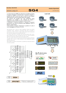
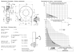
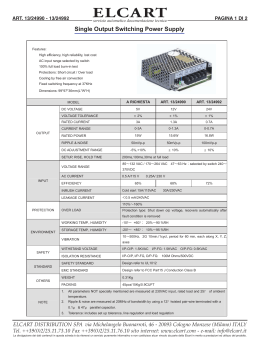
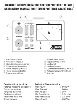
general
equipment
5.4
5.4.1
load cells
load cells
page
392
392
5.4.1
load cells
tecnotest
monotronic
digital control unit
monotronic - microprocessor
digital control unit
AD 005
This Monotronic is an electronic instrument for reading load cells
having 2 m V/V full scale input. The display can show numbers
between - 30,000 ÷ + 30,000). The unit of measurement, scale
and decimal point are pre-set during calibration of the load cell
togheter with the control unit. Such calibration is carried out by a
university laboratory using a sample cell for reference.
It has a permanent memory pre-set to retain calibration parameters
of up to 4 different cells, thus enabling the Monotronic to
alternately read more than one sensor and call up the identification
number if and when needed.
It is also equipped with a tare function and serial port RS 232
interface for printer or PC.
Specifications:
- Graphic display: 60 x 32 mm
- Current value “HOLD” key
- “TARE” key
- Peak value memorisation
- Unit of measurement: kN, daN, N
- Power supply: 220 V, 50Hz, single phase via external adaptor
- Transducer input: 2 mV/V; 3 mV/V; 7 mV/V
- Transducer power supply: 10 V
CALIBRATION function allows:
- Testing of output devices for malfunctions
- Testing of non-volatile memory for malfunctions
- Testing of analog-digital converter for malfunctions
- Testing of displays and keypads for malfunctions
- Machine set-up
- Keypad input of calibration parameters
- Procedure for semi-automatic calibration on 11 points
equally divided over the full scale
accessory:
AD 013/B02
AP 038/3
AD 005
PRINTER
It can be connected to the Monotronic
for printing current value and peak value
AD 013/B02
393
load cells
tecnotest
5.4.1
electronic column load cells
Load cells are high quality instruments used to measure force;
the mechanics of the column type load cell make it suitable for
use under compression and it is therefore ideal for checking
weights or, as a dynamometer, calibrating testing machines that
work in compression.
The heart of the device is a special, treated, stainless steel
column on which eight electric STRAIN GAUGES are located
in specific positions.
Any load applied causes the elastic deformation of the column
and strain gauges which, in turn, causes a modification of the
electrical voltage in the circuit which can be read and converted
into engineering units by means of an appropriate electronic unit.
AP 037/001
Tecnotest’s range of cells comprises models with full scales
from 1 kN to 5000 kN.
The initial calibration is performed by our metrologic laboratory
(AS series) or by an Independent Laboratory (AP series),
authorised to certify such kind of cells.
NOTE: SIT (Italian accredited laboratory verification) certificate
available only on request.
N.B. On request, the same cells are available with different
accuracy classes:
EN 0.5 up to 100 kN - EN 1 from 300 to 1000 kN
AP 037/005
AP 038/01
AP 038/3
AP 038/5
MODELS AVAILABLE:
AP Series
AS Series
AP 037/001
AP 037/003
AP 037/005
AP 037/010
AP 037/025
AP 038/005
AP 038/007
AP 038/01
AP 038/03
AP 038/06
AP 038/1
AP 038/2
AP 038/3
AP 038/5
AS 037/001
AS 037/003
AS 037/005
AS 037/010
AS 037/025
AS 038/005
AS 038/007
AS 038/01
AS 038/03
AS 038/06
AS 038/1
AS 038/2
AS 038/3
AS 038/5
1 kN LOAD CELL – EN 1 - ø mm 63 x 94 (h) – 0.800 kg
3 kN LOAD CELL – EN 1 - ø mm 63 x 94 (h) – 0.800 kg
5 kN LOAD CELL – EN 1 - ø mm 57 x 117 (h) – 2.1 kg
10 kN LOAD CELL – EN 1 - ø mm 57 x 117 (h) – 2.1 kg
25 kN LOAD CELL – EN 1 - ø mm 57 x 117 (h) – 2.1 kg
50 kN LOAD CELL – EN 1 - ø mm 82 x 149 (h) – 5.2 kg
75 kN LOAD CELL – EN 1 - ø mm 82 x 148 (h) – 5.2 kg
100 kN LOAD CELL – EN 1 - ø mm 82 x 148 (h) – 5.2 kg
300 kN LOAD CELL – EN 2 - ø mm 135 x 200 (h) – 14 kg
600 kN LOAD CELL – EN 2 - ø mm 135 x 200 (h) – 15 kg
1000 kN LOAD CELL – EN 2 - ø mm 135 x 200 (h) – 16 kg
2000 kN LOAD CELL – EN 2 - ø mm 135 x 200 (h) – 19 kg
3000 kN LOAD CELL – EN 2 - ø mm 135 x 200 (h) – 21 kg
5000 kN LOAD CELL – EN 2 - ø mm 180 x 200 (h) – 36 kg
Every load cell having capacity up to 100 kN is supplied complete with ball seating device for use in compression.
394
5.4.1
load cells
tecnotest
universal digital readout unit for
dynamometers and load cells
Designed for use in the most advanced and highly accurate static
and dynamic measuring systems, such as those used in Metrology
Laboratories, material testing equipment, test or inspection
benches, etc.
It is highly recommended that it be periodically certified by an
authorised body in combination with dynamometers, load cells
(having 4 or 6 wires) or unamplified pressure transducers.
Input comprises a chain formed by a highly-accurate analog circuit
having long-term stability, as well as a frequency generator used
for supplying power to 6-wire dynamometers and an A/D converter
with a resolution of ± 500,000 divisions.
In order to work at a highly-stable resolution of ± 200,000 divisions (at
2 mV/V), the readout unit has an internal reference (with guaranteed
variation of 1 ppm/°C) which may be periodically checked by
means of self-calibration function. User interface is guided by an
LCD graphic display lit from the back (240 x 64 resolution) and by
5 function keys allowing full channel programming.
Models:
two channel readout unit
AP 045
The units may be individually programmed and calibrated by the
user.
This version may also be equipped with an optional RS232C,
24-column printer interface and remote print input.
AP 045/1
Serial interface RS-232C for
AP 045 readout unit
ten channel readout unit
AP 048
All 10 channels may be individually programmed and calibrated
by the user using point calibration (5 known points) or polynomial
calibration (1st, 2nd or 3rd degree) as per official certificates issued
by the competent authorities.
Calibration using these systems enables the dynamometer and
readout unit to be linearized, thus eliminating any uncertainty in
final measurement.
RS232C, a 24-column printer interfaces and remote print input are
provided as standard.
connection device load cell/readout
unit
(needed
AP 050
for each load cell) AP 049
Printer for AP 045 - AP 048
remote button switch for readout
units ap 045 and ap 048
AP 046/P
395
load cells
tecnotest
5.4.1
metrological load cells (bidirectional)
for u.t.m. calibration
Used in calibration operations as reference cell:
bidirectional for U.T.M. (compression/tensile) and complete with
the ball-seating for compression purposes.
Tensile grips are not included and must therefore be ordered apart.
Supplied with a calibration Certificate issued by an indipendent
Laboratory authorized to the certifications.
On request, a SIT certification according to: ISO 376
(class 1) - EN 10.002-3 (class 1) ASTM E74 (class A) can be
supplied.
Stainless steel made. Electric lead 5 m.
BALL
SEATING
Accuracy class: 1 (EN 10002 - 3 and ISO 376)
LINEARITY - HYSTERESIS: ≤ ± 0.02% f.s.
RELATIVE ERROR (on reading):
- repeatability (0°-120°-240°): ≤ ± 0.080%
- interpolation (2° equation): ≤ ± 0.050%
- zero: ≤ ± 0,010% - reversibility: ≤ ± 0.90%
EFFECT OF A TEMPERATURE OF 10°C:
- on zero: ≤ ± 0.015% - on sensitivity: ≤ ± 0.010%
NOMINAL SENSITIVITY: 2mV/Volt
SENSITIVITY TOLERANCE: ≤ ± 0.1%
RECOMMENDED SUPPLY VOLTAGE: 10 V (max. 18 V)
MECHANICAL LIMIT VALUES (NOMINAL LOAD)
- service load: 120% F.S.
- max permissible load: 150% F.S.
- failure load: > 300% F.S.
- max permissible dynamic load: 75% F.S.
NOMINAL TEMPERATURE RANGE: -10/+40 °C
PROTECTION GRADE (EN 60529): IP67
BASE
AP 033
dimensions:
weight:
diameter 230 x 250 (h) mm.
36 kg.
metrological load cell 750 kn capacity
(without
readout unit)
AP 031
AP 033
AP 033/T
metrological load cell 1000 kn
(without
readout unit)
tensile grips
(for
AP 033
ap 031 and ap 033) AP 033/T
High resistance steel: connection threading M 80 x 2 - 70 mm long.
Official “SIT” Certificate - Class 1
AP 031/CC
AP 031/CT
AP 031/CB
compression
tension
compression/tension
The load cells AP 031 and AP 033 need to be coupled with a
signal processor adequate to the required accuracy class. A
microprocessor-controlled amplifier for obtaining the best results
(resolution 200,000 digits) is suggested.
The picture shows, the model AP 048. Its carrier frequency is 440
Hz (preferable to the usual a.c. power).
Many important functions are provided and the remote control via
RS 232 interface is a standard device.
AP 048
Our two and ten channel universal signal readout
units for 2-10 channels (AP 045 and AP 048)
are illustrated on page 394
396
5.4.1
load cells
tecnotest
compression frame stability verification system
(foote meter test)
en 12390-4
European Standard EN 12390-4 appendix A prescribes that
compression testing machines comply with requirements for
stability test (commonly known as the Foote Meter test), more
specifically:
- accuracy of force indication
- self-alignment of the upper machine platen
- alignment of the component parts of the machine
- restraint on movement of the upper platen
AP 300
AP 300/S
The system comprises:
strain load cell with 4 strain
gauges 3000 kn capacity
AP 300
The strain load cell is fitted with four strain gauge bridges (4
outputs) for verifying behaviour during loading, with a fifth strain
gauge (5th output) for verifying force accuracy (for use as a load
cell during normal calibration tests).
Complete with 5 cables and relevant connectors.
AP 300/P
dimensions:
weight:
220 x 130 x 200 (h) mm.
17 kg.
positioning/testing platen
(for
ap 300) AP 300/P
Made of special, rectified steel, it allows positioning and centring of
the load cell (strain gauged load cell) on the lower auxiliary platen
with 6 mm offset, as prescribed by the Standard.
dimensions:
weight:
150 x 150 x 40 (h) mm.
7 kg.
AP 300
AP 300/S
AP 300/P
397
5.4.1
load cells
tecnotest
digital, 4 channel strain
indicator for ap 300
AP 300/S
Connected to a load cell (strain gauged load cell AP 300) allows
simultaneous readout of 4 channels while verifying behaviour of
the compression testing machine during loading phase.
Fitted with serial port RS 232C for transmission of data to a PC.
dimensions:
weight:
255 x 270 x 120 (h) mm.
3 kg.
AP 300/S
RAPPORTO DI VERIFICA TECNOTEST No 124/2007
RISULTATI DELLA VERIFICA
MISURE: PROCEDURA A.2 EN12390/4 APPENDICE A
CLIENTE
MODELLO MACCHINA
KD 300
COSTRUTTORE
TECNOTEST
ANNO DI COSTRUZIONE
2007
MATRICOLA
2392
CARICO MASSIMO 3000kN
RISOLUZIONE
LUOGO DELLE MISURE
TEMPERATURA
FORZA (kN)
200
200
200
200
FORZA (kN)
200
200
200
200
NORMATIVA DI RIFERIMENTO EN 12390-4:2000
REQUISITI RIPORTATI NELLA TABELLA 3 DELLA NORMATIVA EN 12390/4
autoallineamento del allineamentop dei
limitazione del piatto
piatto superiore della
componenti della
superiore
macchina
macchina
requisiti rapporto di
requisiti rapporto di deformazione per mm
deformazione
deformazione medio
di spostamento
max 0.10
max +/-0.10
max 0.04
N/A
N/A
max 0.06
FORCE (kN)
200
2000
200
2000
200
2000
200
2000
200
2000
C
2
3
4
D
1
A
Data
Il tecnico
piatto ausiliario quadrato
A: fronte macchina
B: sinistra
C: retro
D: destra
1-2-3-4: centro dei 4 ponti
150mm
FORZA (kN)
200
2000
200
2000
200
2000
200
2000
26/06/2007
pagina 1 of 3
Data
Il tecnico
AP 300
AP 048
C
ponte 1
204,7
198,8
206,4
206,5
USCITA CELLA DI CARICO (kN)
ponte 2
ponte 3
ponte 4
196,4
203,7
195,8
198,2
201,4
194,0
194,2
203,0
196,4
193,5
202,4
196,0
media
200,15
198,10
200,00
199,60
piatto superiore
inclinato verso
A
C
B
D
ponte 1
0,0227
0,0035
0,0320
0,0346
rapporti di deformazione
ponte 2
ponte 3
ponte 4
-0,0187
0,0177
-0,0217
0,0005
0,0167
-0,0207
-0,0290
0,0150
-0,0180
-0,0306
0,0140
-0,0180
/
/
/
/
/
piatto superiore
inclinato verso
A
C
B
D
B
2
3
4
piatto ausiliario quadrato
A: fronte macchina
B: sinistra
C: retro
D: destra
1-2-3-4: centro dei 4 ponti
D
1
A
150mm
AUTOALLINEAMENTO DEL PIATTO SUPERIORE DELLA MACCHINA
differenza rapporto di
deformazione
MISURE: PROCEDURA A.5 EN12390/4 APPENDICE A
FORZA (kN)
la forza massima deve corrispondere al minimo fra la capacità massima della pressa e 2000kN
B
RAPPORTO DI VERIFICA TECNOTEST No 124/2007
RAPPORTO DI VERIFICA TECNOTEST No 124/2007
Verifica della stabilità in fase di carico di una pressa a compressione
secondo la normativa EN12390/4 appendice A
ponte 1
0,031
ponte 2
0,031
ponte 3
0,004
ponte 4
0,004
limite
0.1
ALLINEAMENTO DEI COMPONENTI DELLA MACCHINA
ponte 1
152,2
1623,1
264,7
2330,6
205,0
1959,6
203,4
1957,5
USCITA CELLA DI CARICO (kN)
ponte 2
ponte 3
ponte 4
249,4
200,2
197,5
2367,4
1980,6
2008,6
140,0
206,2
192,6
1667,0
2018,9
1969,7
196,8
148,5
255,0
2032,0
1653,0
2339,9
198,9
264,3
139,2
2035,6
2348,4
1642,2
media
199,83
1994,93
200,88
1996,55
201,33
1996,13
201,45
1995,93
cella spostata
di 6mm
verso A lungo AC
verso A lungo AC
verso C lungo AC
verso C lungo AC
verso B lungo BD
verrso B lungo BD
verso D lungo BD
verso D lungo BD
bridge 1
-0,2383
-0,1864
0,3177
0,1673
0,0183
-0,0183
0,0097
-0,0193
rapporti di deformazione
bridge 2 bridge 3 bridge 4
0,2481
0,0019
-0,0116
0,1867
-0,0072
0,0069
-0,3030
0,0265
-0,0412
-0,1651
0,0112
-0,0134
-0,0225
-0,2624
0,2666
0,0180
-0,1719
0,1722
-0,0127
0,3120
-0,3090
0,0199
0,1766
-0,1772
/
/
/
/
/
/
/
/
/
cella spostata
di 6mm
verso A lungo AC
verso A lungo AC
verso C lungo AC
verso C lungo AC
verso B lungo BD
verrso B lungo BD
verso D lungo BD
verso D lungo BD
26/06/2007
pagina 2 of 3
rapporto di
deformazione medio
ponte 1
0,023
ponte 2
-0,019
ponte 3
0,016
ponte 4
-0,020
limite
+/- 0,1
LIMITAZIONE DEL PIATTO SUPERIORE DELLA MACCHINA
FORZA (kN)
200
2000
LUNGO AC
0,046
0,029
LUNGO BD
0,048
0,029
limite
0,06
0,04
STRUMENTI CAMPIONE UTILIZZATI
flessiometro capacità 2000kN
Costruttore: TMT - Torino - Italy
modello: C/PA - C/F
Rapporto di verifica TMT del 02-03-2007
matricola: BOY
indicatore estensimetrico digitale - 4 canali
matricola: 42311
Costruttore: AEP - Modena - Italy
modello: MP4
Certificato di collaudo AEP - certificato n° 15207C - 15107C - 15007C - 14907C del 18/05/2007
Data
Il tecnico
26/06/2007
pagina 3 of 3
398
5.4.1
load cells
tecnotest
Scaricare