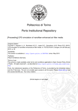
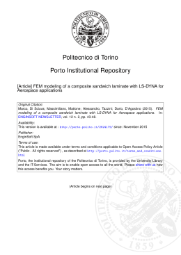
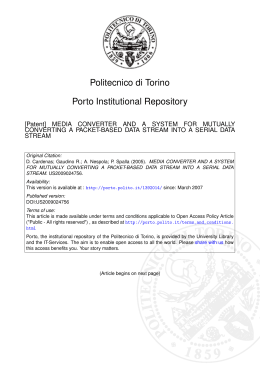
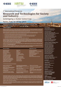
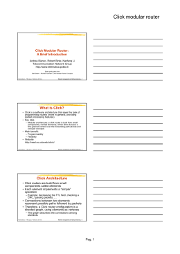
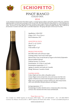
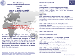
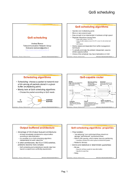
Audio coding Audio coding hints TLC Networks Group [email protected] http://www.telematica.polito.it/ Andrea Bianco – TNG group - Politecnico di Torino Computer Networks Design and Management - 1 Sound perception • Bandwidth: 20 Hz – 20 kHz • Dynamics: ~96 dB • Frequency resolution is not constant: as the frequency increases, the ability to distinguish among sounds at close frequencies decrease • Also the amplitude resolution is not constant • In both cases, very often logarithmic scales are used Andrea Bianco – TNG group - Politecnico di Torino Computer Networks Design and Management - 2 Pag. 1 Audio coding Sound perception • The perceived amplitude is a function of the frequency – For the same intensity a sound is perceived as more or less strong depending on the frequency composing it • Critical bands are frequency bands over which the perceived amplitude is more or less uniform • Critical band size range between 50 Hz (at the minimum audible frequencies) and 4 kHz (at the maximum audible frequencies) • As a first approximation, the audible spectrum can be subdivided in 26 critical bands Andrea Bianco – TNG group - Politecnico di Torino Computer Networks Design and Management - 3 Sound preception – audible area Andrea Bianco – TNG group - Politecnico di Torino Computer Networks Design and Management - 4 Pag. 2 Audio coding Masking • A signal masks (making non audible) signals of smaller amplitude which are close in time or frequency • The masking effect depends on the time or the frequency distance between the two signals • Further dependencies from amplitude, frequency, type (tone or noise) of the masking signal Andrea Bianco – TNG group - Politecnico di Torino Computer Networks Design and Management - 5 Frequency masking Andrea Bianco – TNG group - Politecnico di Torino Computer Networks Design and Management - 6 Pag. 3 Audio coding Audio coding • Non compressed signal, CD quality: – 44100 Hz, 16 bit per sample, two channels – Rate: 1.4 Mbit/s • ADPCM techniques may reduce the bit rate • LPC or CELP cannot be used due to the difficulty in source modelling – Too diverse sources • Best results obtained via psicoacustic coders that exploits the ear charateristics and perceptual limits Andrea Bianco – TNG group - Politecnico di Torino Computer Networks Design and Management - 7 MPEG coding • MPEG (Moving Pictures Experts Group) is a ISO working group that defines standard for audio (and video) signals • The standard specifies the bitstraem format, the coding/decoding ant the conformity test • Details on how to implement the coder(decoder arre not specified – Any designer can pursue its own solution, in the framework defined by the standard – Interoperabilty guaranteed by the standard Andrea Bianco – TNG group - Politecnico di Torino Computer Networks Design and Management - 8 Pag. 4 Audio coding MPEG coding • Lossy compression – Part of the information contained in the original bitstream is lost • Exploiting the ear characteristics and perceptive limitations ear the compression becomes “perceptually lossless” • Group of expert listeners, in optimal hearing conditions, were not able to distinguish between the original bitstream and the coded bitstream with a 6:1 compression ratio Andrea Bianco – TNG group - Politecnico di Torino Computer Networks Design and Management - 9 Coding algorithm • Input signals are the PCM samples • Frequency transform • Spectrum divided in 32 sub-band of the same amplitude • On the basis of the psicoacustic model the masking effects are defined in each subband • As a consequence, the proper number of bits to be used in each sub-band is defined Andrea Bianco – TNG group - Politecnico di Torino Computer Networks Design and Management - 10 Pag. 5 Audio coding Coding algorithm • More precisely: – If the amplitude of the signaling in the sub-band is below the masking threshold, no coding is adopted – Otherwise, the number of bit is enough to ensure that the quantization noise σx2 is below the masking threshold (for each additional bit σx2 decreases by 6 dB) • The frame in the bit stream contains header, number of bit in each sub-band, sample values and some auxiliary info (e.g. CRC) Andrea Bianco – TNG group - Politecnico di Torino Computer Networks Design and Management - 11 Coding and decoding input (PCM) Sub- band decomposition Bit allocation to each sub-band Bitstream fprmatting Sub-band decoding Parameter extraction form the bitstream output (MPEG) Mask computation output (PCM) Time reconstruction Andrea Bianco – TNG group - Politecnico di Torino input (MPEG) Computer Networks Design and Management - 12 Pag. 6 Audio coding Observation • To simplify system implementation, the filter bank used to decompose the signal in sub-bands is not optimal: – The 32 sub-bands have the same size; better results could be obtained if the sub-band were corresponding to the critical band – Decomposing the signal spectrum in sub-band is not exactly reversible; the inverse operation introduces a (small) error – Filter band are not exactly disjoint. Thus, some influence from signals in adjacent sub-band exists Andrea Bianco – TNG group - Politecnico di Torino Computer Networks Design and Management - 13 MPEG-1 Audio (1992) • Three sampling frequences: 32kHz, 44.1kHz e 48kHz • Channel: – – – – Mono (single channel) Dual mono (2 independent channels, e.g. two languages) Stereo (L and R channels independently coded) Joint-stereo (exploit L and R channels correlation and perceptual properties to improve compression ratio) • Bitrate: – Constant and predefined in the range 32 – 224 kbit/s – Different bitrate, possibly variable, are supported Andrea Bianco – TNG group - Politecnico di Torino Computer Networks Design and Management - 14 Pag. 7 Audio coding Layers • Three compression layers are envisioned • Layer 1 is the base layer • Layer 2 and layer 3 enhance system performance exploiting more complex blocks • Roughly speaking, the three layers target applications whose bit rate is larger, equal or smaller than 128 kbit/s • MPEG-1 Layer III is the MP3 format Andrea Bianco – TNG group - Politecnico di Torino Computer Networks Design and Management - 15 Layer I • For each sub-band 12 sample blocks arre considered Sub-band filter 0 12 samples 12 samples 12 samples Sub-band filter 12 samples 12 samples 12 samples Sub-band filter 31 12 samples 12 samples 12 samples Andrea Bianco – TNG group - Politecnico di Torino Computer Networks Design and Management - 16 Pag. 8 Audio coding Layer I • For each block, a number of bit ranging from 0 to 15 is determined, plus a scaling factor • The scaling factor is a multiplicative term that enhances the quantization (as in the APCM), represented with 6 bit • Frame size in bit Header (32) CRC (0,16) Bit allocation (128-256) Scale factors (0-384) Andrea Bianco – TNG group - Politecnico di Torino Samples Ancillary data Computer Networks Design and Management - 17 Layer II • Enhances Layer I performance, by considering groups of 3 blocks of 12 samples each • The same scaling factor for two/three consecutive blocks is used if the difference in dynamics are small enough, or not perceivable due to the time masking effect • More efficient coding for samples, scaling factor and bit allocation Andrea Bianco – TNG group - Politecnico di Torino Computer Networks Design and Management - 18 Pag. 9 Audio coding Layer III • Much more complex • Much better performance • Compensates for non optimal filter characteristic with a “Modified Discrete Cosine Transform” (MDCT): – Sub-bands are further decomposed to enhance spectral resolution – Improve filter quality to reduce the aliasing Andrea Bianco – TNG group - Politecnico di Torino Computer Networks Design and Management - 19 Layer III • Block size dynamically modified (12 or 36 samples) depending on whether it is better to enhance the resolutionin time (transient) or frequency (stationary signals) • More efficient non uniform sample quantization • Entropic coding for quantized values • Enhances the choice of the number of bit for each sub-band with a more sophisticated algorithm Andrea Bianco – TNG group - Politecnico di Torino Computer Networks Design and Management - 20 Pag. 10 Audio coding MPEG-2 Audio (1994) • Multichannel support: up to 5 HI-FI channels plus a low frequency channel (5.1 scheme) • Up to 7 audio channel in several languages • Three new sampling frequencies (16, 22.05 e 24 kHz) • Support also for reduce bitrate, down to 8 kbit/s • Partly compatible with MPEG-1 – MPEG-2 decoder are able to decode MPEG-1 stream – MPEG-2 stream can be formatted to ensure that MPEG1 decoder are able to extract two channels from the stream Andrea Bianco – TNG group - Politecnico di Torino Computer Networks Design and Management - 21 Bibliografia • D. Pan, “A Tutorial on MPEG/Audio Compression”, IEEE Multimedia, Vol. 2 No. 2, pp. 60-74, 1995 • D. Pan, “Digital Audio Compression”, Digital Technical Journal, Vol. 5, No. 2, Spring 1993 • ISO/IEC International Standard IS 11172-3 “Information Technology – Coding of Moving Pictures and Associated Audio for Digital Storage Media at up to 1.5 Mbits/s – Part 3: Audio” Andrea Bianco – TNG group - Politecnico di Torino Computer Networks Design and Management - 22 Pag. 11
Scaricare