19 157-05
PZW
4
4
4
D
Betriebsanleitung
GB Operating instructions
F
Manuel d'utilisation
Sicherheitsbestimmungen
4
4
4
E
Instrucciones de uso
I
Istruzioni per l`uso
NL Gebruiksaanwijzing
Safety Regulations
Conseils préliminaires
• Das Gerät darf nur von Personen installiert und in Betrieb genommen werden,
die mit dieser Betriebsanleitung und den
geltenden Vorschriften über Arbeitssicherheit und Unfallverhütung vertraut sind.
Beachten Sie die VDE- sowie die örtlichen
Vorschriften, insbesondere hinsichtlich
Schutzmaßnahmen.
• Beim Transport, bei der Lagerung und im
Betrieb die Bedingungen nach EN 600682-6 einhalten (s. techn. Daten).
• Durch Öffnen des Gehäuses oder
eigenmächtige Umbauten erlischt jegliche
Gewährleistung.
• Montieren Sie das Gerät in einen Schaltschrank; Staub und Feuchtigkeit können
sonst zu Beeinträchtigungen der Funktionen führen.
• Sorgen Sie an allen Ausgangskontakten
bei kapazitiven und induktiven Lasten für
eine ausreichende Schutzbeschaltung.
• The unit may only be installed and
operated by personnel who are familiar
with both these instructions and the
current regulations for safety at work and
accident prevention.
• Transport, storage and operating conditions should all conform to EN 60068-26.
• Any guarantee is void following opening of
the housing or unauthorised modifications.
• The unit should be panel mounted,
otherwise dampness or dust could lead to
functional impairment.
• Adequate fuse protection must be
provided on all output contacts with
capacitive and inductive loads.
• La mise en oeuvre de l’appareil doit être
effectuée par une personne spécialisée en
installations électriques, en tenant compte
des prescriptions des différentes normes
applicables (NF, EN, VDE..), notamment
au niveau des risques encourus en cas de
défaillance de l’équipement électrique.
• Respecter les exigences de la norme
EN 60068-2-6 lors du transport, du
stockage et de l’utilisation de l’appareil.
• Toutes interventions sur le boîtier (ouverture du relais, échange ou modification de
composants, soudure etc.) faites par
l’utilisateur annulent la garantie.
• Montez l’appareil dans une armoire
électrique à l’abri de l’humidité et de la
poussière.
• Assurez-vous du pouvoir de coupure des
contacts de sortie en cas de charges
inductives ou capacitives.
Bestimmungsgemäße Verwendung
Typical Applications
Domaines d’utilisation
The PZW serves as a Limited Inch Time
Relay
• to EN 292 T2 par 3.7.10. and 4.1.4 and EN
292 T1 par 3.23.8 (inching switch for
limited movement of hazardous machine
parts during installation, setting up and
adjustment.
• Safety circuits according to VDE 0113-1
and EN 60 204-1
(e.g. with movable guards)
The PZW is designed for use with a
• Safety switch unit in the PNOZ series
• Safety gate monitor in the PST series
• Two-hand control relay in the P2HZ series
The category that can be achieved in
accordance with EN 954-1 depends on the
category of the base unit. The PZW may not
exceed this.
Le PZW est un relais à impulsion à l'appel de
sécurité conforme :
• aux normes EN 292 T2 §. 3.7.10 et 4.1.4
et EN 292 T1 §. 3.23.8 (marche coup par
coup des mouvements dangereux pendant
les travaux de montaet de réglage)
• aux circuits de sécurité selon les normes
VDE 0113-1 et EN 60 204-1 (ex.
protecteurs mobiles)
Le PZW peut être utilisé en liaison avec:
• un bloc logique d'arrêt d'urgence PNOZ
• un relais de surveillance protecteur PST
• un relais de commande bimanuelle P2HZ
La catégorie à atteindre conformément à la
norme EN 954-1 dépend de la catégorie de
l'appareil de base. Elle ne peut pas être
dépassée par le PZW.
Description
Description de l’appareil
The Limited Inch Time Relay is enclosed in a
P-97 housing. There are different versions
available for AC operation and 1 for DC
operation.
Features:
• Relay outputs:
1 safety contact (n/o), positive-guided
2 auxiliary contacts (2 n/c), positive-guided
• LED Display for operating voltage/ "Power"
• LED Display for pulse on/ "Out"
• 12 adjustable pulses lengths via rotary
switch
• Output circuit is redundant
• Feedback control loop for monitoring
external contactors/relays.
Inséré dans un boîtier P-97, le relais de
sécurité PZW est disponible en différentes
versions pour les tensions de commande
alternative et une version en 24 VCC.
Caractéristiques :
• Contacts de sortie :
1 contact à fermeture de sécurité (F)
et 2 contacts de signalisation (O)
• LED d'indication présence tension
• LED d'indication état du relais de sortie
• 12 temps d'impulsion réglables par
commutateur
• Sorties redondantes
• Boucle de retour pour l'auto-contrôle des
contacteurs externes.
Das Sicherheitszeitrelais PZW dient als
Wischrelais (Impulsrelais)
• nach EN 292 T2 Abs. 3.7.10 und 4.1.4 und
EN 292 T1 Abs. 3.23.8 (Schrittschaltung
für begrenzte Bewegung gefahrbringender
Maschinenteile während Montage-,
Einricht- und Einstellarbeiten)
• in Sicherheitsstromkreisen nach
VDE 0113 und EN 60 204-1 (z. B. bei
beweglichen Verdeckungen)
Das Gerät ist bestimmt für den Einsatz mit
einem
• Sicherheitsschaltgerät der Reihe PNOZ
• Schutztürwächter der Reihe PST
• Zweihandbedienungsrelais der Reihe P2HZ
Die zu realisierende Kategorie nach
EN 954-1 ist abhängig von der Kategorie des
Grundgeräts. Sie kann vom PZW nicht
überschritten werden.
Gerätebeschreibung
Das Sicherheitszeitrelais PZW ist in einem
P-97-Gehäuse untergebracht. Es stehen
verschiedene Varianten für den Betrieb mit
Wechselspannung und eine Variante für den
Betrieb mit Gleichspannung zur Verfügung.
Merkmale:
• Relaisausgänge:
1 Sicherheitskontakt (S), zwangsgeführt
2 Hilfskontakte (Ö), zwangsgeführt
• LED als Versorgungsspannungsanzeige
• LED als Schaltzustandsanzeige
• 12 Wischzeiten durch Drehschalter
einstellbar
• redundante Ausgangsschaltung
• Rückführkreis zur Überwachung externer
Schütze.
-1-
Das Schaltgerät erfüllt folgende Sicherheitsanforderungen:
• Die Sicherheitseinrichtung bleibt auch in
folgenden Fällen wirksam:
- Ausfall eines Bauteils
- Spulendefekt
- Leiterbruch
• Überprüfung bei jedem Ein-Aus-Zyklus, ob
die Ausgangsrelais des Sicherheitsgerätes
richtig öffnen und schließen.
The relay complies with the following safety
requirements:
• The safety function remains effective in the
following cases:
- Component failure
- Coil defect in a relay
- Cable break
• The correct opening and closing of the
safety function relays is tested
automatically in each on-off cycle.
Le relais répond aux exigences suivantes:
• La sécurité est garantie, même dans les
cas suivants:
- Défaillance d'un composant
- Défaillance bobine
- Défaut soudure
• Vérification à chaque cycle d'ouverture/
fermeture du bon fonctionnement des
relais internes.
Funktionsbeschreibung
Function Description
Description du fonctionnement
Das Sicherheitszeitrelais PZW dient zum
schrittweisen Steuern von Bewegungsabläufen in Sicherheitsstromkreisen.
Die Wischzeit tw (Impulszeit) ist in 12 Stufen
einstellbar. Mit dem Schließen des Rückführkreises ist das Zeitrelais startbereit.
Das Zeitrelais wird durch Schließen und
Unterbrechen des Eingangkreises
(Versorgungsspannung) gesteuert. Das
Gerät ist im Ruhezustand, solange der
Eingangskreis A1-A2 unterbrochen ist. Der
Sicherheitskontakt 17-18 ist offen, die
Hilfskontakte 25-26 und 35-36 sind geschlossen.
Nach Schließen des Eingangskreises
leuchtet die LED "Power". Die beiden
Ausgangsrelais K1 und K2 ziehen sofort an
und der Zeitablauf beginnt. Die LED "Out"
leuchtet. Nach Ablauf der eingestellten
Wischzeit fallen die Ausgangsrelais ab und
der Sicherheitskontakt 17-18 öffnet und die
Hilfskontakte 25-26 und 35-36 schließen
wieder. Die LED "Out" erlischt.
Der Eingangskreis muss mindestens solange
wie die eingestellte Wischzeit tw geschlossen
sein. Bei vorzeitigem Unterbrechen des
Eingangs- oder Rückführkreises wird der
Zeitablauf abgebrochen.
The Fail Safe Limited Inch Timer PZW is
designed to control machine movement
during setting, testing etc. The pulse times
tw are adjustable in12 steps.
The unit is in the rest position as long as the
supply to A1-A2 is broken, the safety
contact 17-18 is open and the auxiliary
contacts 25-26 and 35-36 are closed. When
the feedback control loop is closed the time
relay is ready for operation.
The inch time is started by switching the
supply to A1-A2.
After closing the input circuit the LED
"Power" is illuminated. Both output relays
K1 and K2 immediately energise and the
time cycle begins. After the set pulse time
the output relays de-energise and the safety
contact 17-18 opens and the auxiliary
contacts 25-26 and 35-36 close. The LED
"Out" goes out.
The input circuit must be closed at least as
long as the set pulse time tw. By premature
breaking of the input or the feedback control
loop, the time cycle will be terminated.
Le relais temporisé de sécurité PZW permet
d'assurer une commande impulsionnelle
sûre (marche par à-coups) de mouvements
dangereux. Le temps d'impulsion tw est
réglable. Dès la fermeture de la boucle de
retour, le relais est prêt à fonctionner. Le
PZW est piloté par la fermeture puis la
coupure du circuit d'entrée (tension
d'alimentation). Le PZW reste au repos tant
que le circuit A1-A2 est coupé.
Le contact de sécurité 17-18 est ouvert, les
contacts d'info. 25-26 et 35-36 sont fermés.
Dès la mise sous tension du PZW, la LED
"Power" s'allume. Les relais internes K1 et
K2 passent en position travail (contact
17-18 fermé, contacts 25-26/35-36 ouverts)
et la temporisation commence.
La LED "Out" s'allume. Au bout du temps
affiché, les relais de sortie retombent, le
contact de sécurité 17-18 s'ouvre et les
contacts d'info. 25-26/35-36 se ferment.
La LED "Out" s'éteint.
La durée de la mise sous tension doit être
supérieure au temps d'impulsion tw
sélectionné. En cas d'ouverture prématurée
du circuit d'entrée ou de la boucle de retour,
la temporisation est interrompue
immédiatement.
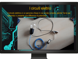
Eingangskreis
Input circuit
Canal d'entrée
Rückführkreis
Feedback Control Loop
Boucle de retour
A1
A2
(L+) U B (L-)
Y1
Y2
17
25
35
S1
.....
G1
~
1
2
11
12
tW
1
1
Zeitkreis 1
Time Circuit 1
Circuit tempo. 1
2
Zeitkreis 2
Time Circuit 2
Circuit tempo. 2
3
Steuerlogik
Start-up logic
Logique de commande
4
Selbsttest
Self check
Auto-test
3
K1
=
K1
4
K2
.....
1
2
11
12
tW
2
3
K2
PZW
18
Fig. 1: Schematisches Schaltbild/Wiring diagram/Schéma interne
-2-
26
36
Eingangskreis
Input circuit
Canal d'entrée
UB
1
0
Rückführkreis
Feedback Control Loop
Boucle de retour
1
Ausgang
Output
Sortie
1
0
0
tw
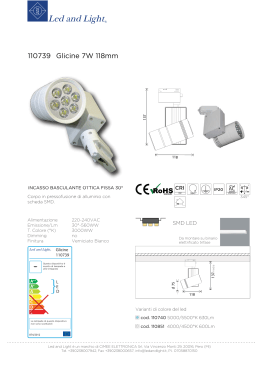
(1)
= Undefinierter Zustand
(1) = Normaler Arbeitszyklus
(2) = Fehlbedienung: Eingangskreis zu
früh geöffnet
(3) = Fehlbedienung: Rückführkreis zu
spät geschlossen innerhalb von tw
(4) = Fehlbedienung: Rückführkreis zu
spät geschlossen nach Ablauf von tw
tw = Wischzeit (Impulszeit)
(1)
(2)
(3)
(4)
tw
tw
tw
(2)
(3)
= Non-defined condition
= Normal work cycle
= Fault condition: Input circuit opened
too early
= Fault condition: Feedback control loop
closed too late within tw
= Fault condition: Feedback control loop
closed too late after tw
= Pulse time
(4)
= Etat indéfini
(1) = Functionnement normal
(2) = Défaut: ouverture prématurée du
circuit d'entrée
(3) = Défaut: fermeture boucle de retour
trop tardive dans l'intervalle tw
(4) = Défaut: fermeture boucle de retour
après écoulement de tw
tw = temps d'impulsion
Fig. 2: Funktionsdiagramm/Pulse diagram/Diagramme fonctionnel
Montage
Installation
Montage
Das Gerät muss in einen Schaltschrank mit
einer Schutzart von mind. IP 54 eingebaut
werden. Zur Befestigung auf einer Normschiene hat das Gerät ein Rastelement auf
der Rückseite.
The unit must be panel mounted (min. IP 54).
There is a moulding on the rear of the unit for
DIN-Rail attachment.
Le relais doit être installé dans une armoire
ayant un indice de protection IP 54. Sa face
arrière permet un montage sur rail DIN.
Inbetriebnahme
Operation
Mise en oeuvre
Beachten Sie bei der Inbetriebnahme:
• Vor die Ausgangskontakte eine
Sicherung (s. techn. Daten) schalten,
um das Verschweißen der Kontakte zu
verhindern.
• Hilfskontakte 25-26 und 35-36 nicht für
Sicherheitsstromkreise verwenden!
• Leitungsmaterial aus Kupferdraht mit einer
Temperaturbeständigkeit von 60/75 °C
verwenden.
• Angaben im Kapitel "Technische Daten"
unbedingt einhalten.
• Bei Geräten für 24 V DC können Querschlüsse zwischen Eingangskreis und
Rückführkreis oder Erdschlüsse im Rückführkreis das Gerät beschädigen.
Wir empfehlen die Verwendung einer
kurzschlußssfesten Spannungsversorgung
mit Strombegrenzung.
Please note for operation:
• To prevent a welding together of the
contacts, a fuse (see technical detail)
must be connected to protect the
output contacts.
• Auxiliary contacts 25-26 and 35-36 are not
to be used for safety circuits
• Use copper wire that can withstand
60/75 °C
• Important details in the section „Technical
Data“ should be noted and adhered to.
• With units for 24 VDC, shorts across the
input contacts between the input circuit
and the feedback control loop or earth
faults in the feedback control loop may
cause damage to the unit. Therefore,the
use of short circuit proof voltage supply
with current limitations is recommended.
Remarques préliminaires:
• Protéger les contacts de sortie par des
fusibles (voir les caractéristiques
techniques) pour éviter leur soudage
• Ne pas utiliser les contacts de
signalisation 25-26 et 35-36 pour les
circuits de sécurité.
• Utiliser uniquement des fils de cablâge en
cuivre 60/75 °C.
• Respecter les données indiquées dans le
chapitre „Caractéristiques techniques“.
• Pour les relais alimentés en 24 VCC, un
court-circuit entre l'alimentation et la
boucle de retour ou la masse et la boucle
de retour risque de détiorier l'appareil.
Nous vous conseillons donc l'utilisation
d'une alimentation protégée contre les
surintensités et les c.c.
Connection and setting
• Connect the input circuit (operating
voltage) to terminals A1 (+) and A2 (-).
• Feedback control loop:
Connect the N/C contact of the relay to be
monitored to the feedback control loop
Y1-Y2 or, if not used link Y1-Y2.
• Set the rotary switch to required pulse
time.
Branchement et réglage
• Amener la tension d’alimentation aux
bornes A1 (+) et A2 (-).
• Boucle de retour:
Câbler les contacts à ouverture des
contacteurs à surveiller dans la boucle de
retour Y1-Y2 ou - quand ce n'est pas
nécessaire - relier les bornes Y1-Y2.
• Sélectionner le temps d'impulsion à l'aide
du commutateur.
Anschluss und Einstellung
• Eingangskreis (Versorgungsspannung) an
Klemmen A1 (+) und A2 (-) anschließen.
• Rückführkreis:
Öffnerkontakte der zu überwachenden
Schütze am Rückführkreis Y1-Y2
anschließen oder - wenn nicht benötigt Brücke Y1-Y2 einlegen.
• Drehschalter auf gewünschte Wischzeit
einstellen.
Ablauf
Ist der Eingangskreis unterbrochen (Ruhezustand), ist der Sicherheitskontakt 17-18 offen
und die Hilfskontakte geschlossen.
Die Leuchtdioden "power" und "out" leuchten
nicht.
Wird der Eingangskreis geschlossen, leuchtet
die LED "power". Der Sicherheitskontakt 17-18
schließt, die Hilfskontakte öffnen und die LED
"out" leuchtet.
Nach Ablauf der eingestellten Wischzeit
kehren die Kontakte in die Ruhelage zurück
und die LED "out" erlischt.
To operate
The input circuit is interrupted (rest
position), the safety contact 17-18 opens
and the auxiliary contacts close. The LEDs
"power" and "out" are not illuminated.
If the input circuit closes, the LED "power"
illuminates. The safety contact 17-18 closes,
the auxiliary contacts open and the LED
"out" is illuminated. After the cycle of the set
pulse time, the contacts revert back to the
rest position (de-energise) and the LED
"out" goes out.
-3-
Fonctionnement
Si le circuit d'entrée est coupé (position
repos), le contact de sécurité 17-18 est
ouvert et les contacts d'info. sont fermés.
Les LEDs "power" et "out" sont éteintes.
Dès que le PZW est mis sous tension,
la LED "power" s'allume. Le contact 17-18
se ferme et les contact d'info s'ouvrent.
La temporisation commence et la LED "out"
s'allume. Au bout de la temporisation
affichée, les contacts de sortie reviennent
en position repos et la LED "out" s'éteint.
Anwendung
Application
Utilisation
In der folgenden Anwendungsschaltung nach
Fig. 3 überwachen der Schutztürwächter
PST1 und die Sicherheitsendschalter S4 und
S5 eine Schutztüre, die den Zugang zu
gefährlichen Maschinenteilen verhindert. Die
Kontakte der Steuerschütze K1 und K2 sind
redundant in die Maschinensteurung
eingebunden.
Die Rückführkreise X1-X2 und Y1-Y2
überwachen K1 und K2. Im Normalbetrieb
(Stellung S2 wie gezeichnet) wird die
Maschine stillgesetzt, sobald die Türe
geöffnet wird (PST1 schaltet K1 und K2 ab).
Für Wartungs- und Montagezwecke können
gefährliche Maschinenteile mit einer Handsteuerung schrittweise bewegt werden. Das
Umschalten auf schrittweisen Betrieb muss
durch einen in beiden Stellungen abschließbaren Schlüsselschalter (S2) erfolgen
(EN 292 T2 Abs. 4.1.4, 3.7.9, 3.7.10 und EN
292 T1 Abs. 3.23.8). Damit können die Teile
(z. B. Werkzeuge) in die erforderliche
Stellung gebracht werden.
Mit dem Schlüsselschalter S2 wird der
schrittweise Betrieb aktiviert. Wird der Taster
S3 betätigt, schaltet das Zeitrelais PZW die
Maschine ein. Nach der eingestellten
Wischzeit bleibt die Maschine wieder stehen.
In the following Application Note Fig. 3 the
Safety Gate Monitor PST 1 and the limit
switches S4 and S5 monitor a guard, which
denies access to dangerous machine parts.
The contacts of the control relays K1 and K2
are integrated in the machine control and are
connected in series. The feedback control
loops X1-X2 and Y1-Y2 monitor K1 and K2.
In normal operation (S2 as shown) the
machine will stop as soon as the gates are
opened (PST 1 allows K1 and K2 to deenergise). For maintenance and setting,
dangerous machine parts can be operated
with inching control. The inch function is
switched using a key operated switch (S2),
according to EN 292 T2 par. 4.1.4, 3.7.9,
3.7.10 und EN 292 T1 par. 3.23.8.
When the key switch S2 is set to the override position, the jogging circuit is enabled.
The PZW is activated using the inch button
S3 and the machine jogs for the set pulse
time. After the set pulse time has elapsed,
the PZW de-energises and the machine
comes to a standstill. Releasing and repressing S3 will allow each further movement.
Dans l'exemple de la fig.3, le relais PST 1
surveille un protecteur mobile qui permet
l'accès à une zone dangereuse.
Les boucles de retour auto-contrôlent les
relais K1 et K2. En fonctionnement normal
(position S2 comme représentée sur
schéma), la machine est arrêtée
immédiatement dès l'ouverture du protecteur
(PST 1 coupe K1 et K2). En cas de réglage
ou en cours de montage, les mouvements de
la machine peuvent être pilotés
manuellement (marche à-coups).
La sélection de ce mode de fonctionnement
doit se faire par un sélecteur à clé, conformément aux normes EN 292 T2
§. 4.1.4, 3.7.9, 3.7.10 et EN 292 T1
§. 3.23.8).
Le sélecteur S2 permet de sélectionner le
mode marche à-coups. Dès que le poussoir
S3 est actionné, le relais PZW pilote la
machine. Au bout du temps d'impulsion
sélectionné, la machine s'arrête.
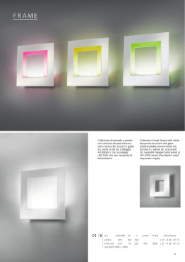
Das Gerät nur wie in dieser Abbildung
anschließen! Nicht bezeichnete Klemmen
dürfen nicht angeschlossen werden.
Only connect the unit as shown in the
following example! Do not connect
unlabelled terminals!
Câbler l'appareil uniquement comme
l'indiquent le schéma suivant! Les bornes
non représentées ne doivent pas être
raccordées.
1L1
(1L+)
S1
S2
K1
K2
S3
A1
13
23 S11 S12
S4
A1 17 25 35 Y1 Y2
X1 X2
K1
PZW
K1 K2
S5
14
Fig. 3: Anwendungsschaltung
Application diagram
Schéma d'application
18 26 36
PST 1
24
K1
A2
K2
S23 S24 A2
K2
1L2
(1L-)
Überprüfung - Fehlerursachen
Testing - Fault causes
Vérification - sources d’erreur
Durch Anschluss der Versorgungsspannung
kann überprüft werden, ob das Gerät
einschaltet und nach Ablauf der Wischzeit
wieder ordnungsgemäß ausschaltet.
Das Gerät kann aus Sicherheitsgründen bei
folgenden Fehlern nicht gestartet werden:
• Fehlfunktion der Kontakte:
Bei verschweißten Kontakten ist nach
Öffnen des Eingangskreises keine neue
Aktivierung möglich.
The unit can be tested by suppling the supply
voltage. The relay should pulse on for the set
time.
For safety reasons, the unit cannot be
activated if the following faults are present:
• Faulty contact functions:
In the case of welded contacts, no further
activation is possible after opening the
input circuit.
La mise sous tension du PZW permet de
vérifier son bon fonctionnement (retombée
du relais au bout du temps d'impulsion
affiché).
Pour garantir la fonction de sécurité, le relais
n'est pas réarmé en cas des défauts
suivants:
• Défaut de fonctionnement des contacts de
sortie: en cas de soudage d'un contact lors
de l'ouverture du circuit d'entrée, un
nouveau réarmement est impossible.
-4-
Technische Daten/Technical Data/Caractéristiques techniques
Versorgungsspannung UB/Operating Voltage UB/Tension d'alimentation UB
AC: 110-120 V, 230 V
DC: 24 V
Spannungstoleranz UB /Voltage Tolerance UB /Plage de la tension d'alimentation UB
-15 % /+10 %
Frequenzbereich/Frequency Range/Fréquence
AC: 50 ... 60 Hz
Restwelligkeit UB /Residual Ripple UB /Ondulation résiduelle UB
10 %
Leistungsaufnahme bei UB /Power Consumption at UB /Consommation pour UB
AC: 4,5 VA; DC: 3 W
Anzahl der Ausgangskontakte/Number of output contacts/Nombre de contacts de sortie
Sicherheitskontakte (S) verzögert/Safety contacts (N/O) delayed/Contacts de sécurité (F)
temporisés
Hilfskontakte (Ö) verzögert/Auxiliary contacts (N/C) delayed/Contacts d'information (O)
temporisés
1
Kategorie der Sicherheitskontakte nach EN 954-1/ Category of safety contacts in accordance
with EN 954-1/Catégorie des contacts de sécurité selon EN 954-1
Verzögerungszeit <30 s/Delay time <30 s/Temporisation <30 s
PZW 3, PZW 30
Verzögerungszeit >30 s/Delay time >30 s/Temporisation >30 s
PZW 30
Kontaktwerkstoff/Contact Material/Matériau des contacts
2
3
1
AgSnO2 + 0,2 µm Au
Gebrauchskategorie nach/Utilization Category to/Catégorie d'utilisation d'après
EN 60 947-4-1
EN 60 947-5-1 (DC13: 6 Schaltspiele/Min, 6 cycles/min, 6 manoeuvres/min)
Einschaltverzögerung/Switch-on delay/Temps de réarmement
AC1: 240 V/0,01... 6 A/1500 VA
DC1: 24 V/0,01... 6 A/150 W
AC15: 230 V/4 A; DC13: 24 V/3 A
AC: 100 ms
DC: 50 ms
Wiederbereitschaftszeit bei max. Schaltfrequenz 1/s/recovery time at max. switching frequency 1/s/
temps de remise en service en cas de fréquence de commutation max. 1/s
80 ms
Wiederholgenauigkeit (tw)/Repetition accuracy (tw)/Précision en reproductibilité (tw)
±1%
Einstellbare Zeitwerte/Adjustable time values/Temps d'impulsion réglables PZW 3 s
PZW 30 s
0,05/0,1/0,2/0,3/0,4/0,5/0,7/1,0/1,5/2/2,5/3 s
0,5/1/2/3/4/5/7/10/15/20/25/30 s
Einstellgenauigkeit/Setting accuracy/Précison de réglage
Bereichsanfang/Beginning of range/Début de gamme
Bereichsende/End of range/Fin de gamme
0,03 s
0,6 s
Abweichung vom Einstellwert tw bei/Deviation from adjusted value tw at/
Varation de valeur tw pour
Spannungsänderung (UB)/Voltage change (UB)/Varation da la tension (UB)
Temperaturänderung/Temperature change/Variation de la température
± 0,06 % je/per/par 1 % ΔUB
± 0,1 % je/per/par 1°C
Spannung und Strom am Rückführkreis (Y1-Y2)
Voltage and Current at Feedback control loop (Y1-Y2)
Tension et courant au niveau et de la boucle de retour (Y1-Y2)
24 V DC, 50 mA
Max. zulässiger Einschaltstrom/Max. permitted inrush current on outputs/
Pouvoir de coupure admissible max.
10 A AC
Elektromagnetische Verträglichkeit (EMV)/Electromagnetic Compatibility
Compatibilité électromagnétique (CEM)
EN 60947-5-1, EN 61000-6-2
Luft- und Kriechstrecken/Airgap Creepage/Cheminement et claquage
EN 60947-1
Kontaktabsicherung extern/External Contact Fuse Protection/
Protection externe des contacts de sortie d'après EN 60947-5-1 (IK = 1 kA)
Schmelzsicherung/Blow-out fuse/Fusibles
Sicherungsautomat/Safety cut-out/Dijoncteur
Geräteabsicherung min./max.
Unit Fuse Protection min./max.
Protection du relais min./max.
6 A flink/quick acting/rapide oder /or/ou
4 A träge/slow acting/normeaux
24 V AC/DC: 4 A Charakteristik/
Characteristic/Caractéristiques B/C
1 A/abhängig vom Leitungsquerschnitt
1 A/dependent on cable cross section
1 A/dépend du diamêtre du câblage
Umgebungstemperatur/Operating Temperature/Température d'utilisation
-10 ... +55 °C
Lagertemperatur/Storage Temperature/Température de stockage
-40 ... +85 °C
Klimabeanspruchung/Climate Suitability/Conditions climatiques
EN 60068-2-78
Schwingungen nach/Vibration to/Vibrations d'aprés
EN 60068-2-6
Frequenz/Frequency/Fréquences: 10...55 Hz
Amplitude/Amplitude/Amplitude: 0,35 mm
Max.Querschnitt des Außenleiters (Schraubklemmen)/Max. cable cross section (screw
terminals)/Capacité de raccordement (borniers à vis)
1 Leiter, flexibel/1 core, flexible/1 conducteur souple
2 Leiter gleichen Querschnitts, flexibel mit Aderendhülse, ohne Kunststoffhülse/
2 core, same cross section flexible with crimp connectors, without insulating sleeve/
2 conducteurs de même diamètre souple avec embout, sans chapeau plastique
ohne Aderendhülse oder mit TWIN-Aderendhülse/without crimp connectors or with TWIN
crimp connectors/souple sans embout ou avec embout TWIN
Anzugsdrehmoment für Anschlussschrauben (Klemmen)/
torque setting for connection terminal screws/couple de serrage (bornier)
-5-
0,20 ... 4,00 mm2/24-10 AWG
0,20 ... 2,50 mm2/24-14 AWG
0,20 ... 2,50 mm2/24-14 AWG
0,6 Nm
Schutzarten/Protection/Indice de protection:
Einbauraum (z. B. Schaltschrank)/Mounting (e.g. Panel)/Lieu d'implantation (ex. armoire)
Gehäuse/Housing/Boîtier
Klemmenbereich/Terminals/Bornes
IP 54
IP 40
IP 20
Gehäusematerial/housing material/matériau du boîtier
Gehäuse/Housing/Boîtier
Front/front panel/face avant
PPO UL 94 V0
ABS UL 94 V0
Abmessungen (H x B x T)/Dimensions (H x W x D)/Dimensions (H x L x P)
87 x 45 x 121 mm
Gewicht/Weight/Poids
330 g
Es gelten die 04/04 aktuellen Ausgaben der
Normen.
The version of the standards current at
04/04 shall apply.
Se référer à la version des normes en
vigeur au 04/04.
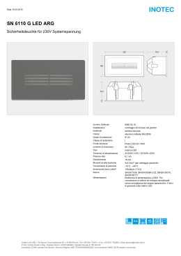
Lebensdauer der Ausgangsrelais/Service Life of Output relays/Durée de vie des relais de sortie
Nennbetriebstrom (A)
Nominal operating current (A)
Courant coupé (A)
10
AC15: 230 V
DC1: 24 V
DC13: 24 V
AC1: 230 V
1
0.1
10
100
1000
Schaltspielzahl x 103
Cycles x 103
Nombre de manvres x 103
10000
122 (4.8")
Abmessungen in mm (")/Dimensions in mm (")/Dimensions en mm (")
75 (2.95")
87 (3.42")
EG-Konformitätserklärung:
EC Declaration of Conformity:
Déclaration de conformité CE :
Diese(s) Produkt(e) erfüllen die Anforderungen der Richtlinie 2006/42/EG über Maschinen des europäischen Parlaments und des
Rates.
Die vollständige EG-Konformitätserklärung
finden Sie im Internet unter www.pilz.com
Bevollmächtigter: Norbert Fröhlich,
Pilz GmbH & Co. KG, Felix-Wankel-Str. 2,
73760 Ostfildern, Deutschland
This (these) product(s) comply with the
requirements of Directive 2006/42/EC of the
European Parliament and of the Council on
machinery.
The complete EC Declaration of Conformity
is available on the Internet at www.pilz.com
Authorised representative: Norbert Fröhlich,
Pilz GmbH & Co. KG, Felix-Wankel-Str. 2,
73760 Ostfildern, Germany
Ce(s) produit(s) satisfait (satisfont) aux
exigences de la directive 2006/42/CE relative aux machines du Parlement Européen et
du Conseil.
Vous trouverez la déclaration de conformité
CE complète sur notre site internet
www.pilz.com
Représentant : Norbert Fröhlich,
Pilz GmbH & Co. KG, Felix-Wankel-Str. 2,
73760 Ostfildern, Allemagne
Technischer Support
+49 711 3409-444
...
Technical support
Assistance technique
+49 711 3409-444
+49 711 3409-444
...
...
In vielen Ländern sind wir durch
unsere Tochtergesellschaften und
Handelspartner vertreten.
In many countries we are
represented by our subsidiaries
and sales partners.
Nos filiales et partenaires
commerciaux nous représentent
dans plusieurs pays.
Nähere Informationen entnehmen
Sie bitte unserer Homepage oder
nehmen Sie Kontakt mit unserem
Stammhaus auf.
Please refer to our Homepage
for further details or contact our
headquarters.
Pour plus de renseignements,
consultez notre site internet ou
contactez notre maison mère.
-6-
www
www.pilz.com
Pilz GmbH & Co. KG
Felix-Wankel-Straße 2
73760 Ostfildern, Germany
Telephone: +49 711 3409-0
Telefax: +49 711 3409-133
E-Mail: [email protected]
Originalbetriebsanleitung/Original instructions/Notice originale
19157-05 -2010-08 Printed in Germany
45
(1.77")
19 157-05
PZW
4
4
4
E
Instrucciones de uso
I
Istruzioni per l`uso
NL Gebruiksaanwijzing
Prescripciones de seguridad
Norme di sicurezza
Veiligheidsvoorschriften
• El dispositivo tiene que ser instalado y
puesto en funcionamiento exclusivamente
por personas que estén familiarizadas,
tanto con estas instrucciones de uso
como con las prescripciones vigentes
relativas a la seguridad en el trabajo y a
la prevención de accidentes. Hay que
observar tanto las prescripciones VDE
como las prescripciones locales, especialmente en lo que se refiere a las medidas
de protección.
• Durante el transporte, el almacenaje y el
funcionamiento hay que atenerse a las
condiciones conforme a EN 60068-2-6
(ver datos técnicos).
• La garantía se pierde en caso de que se
abra la carcasa o se lleven a cabo modificaciones por cuenta propia.
• Montar el dispositivo dentro de un armario de distribución; en caso contrario es
posible que el polvo y la suciedad puedan
afectar el funcionamiento.
• Hay que cuidar de que haya un conexionado de seguridad suficiente en todos los
contactos de salida con cargas
capacitivas e inductivas.
• Il dispositivo può venire installato e messo in funzione solo da persone che conoscono bene le presenti istruzioni per l’uso
e le disposizioni vigenti relative alla sicurezza di lavoro e all’antinfortunistica. Osservare le disposizioni della VDE nonché
le norme locali, soprattutto per quanto
riguarda le misure preventive di protezione.
• Durante il trasporto, l’immagazzinamento
e il funzionamento attenersi alle condizioni prescritte dalla norma EN 60068-2-6 (v.
"Dati tecnici").
• Se viene aperto l’alloggiamento oppure
se vengono apportate modifiche in proprio decade il diritto di garanzia.
• Montare il dispositivo in un armadio elettrico; altrimenti la polvere e l’umidità possono pregiudicare le funzioni.
• Occorre dotare tutti i contatti di uscita dei
carichi capacitivi e induttivi con un circuito
di sicurezza sufficiente.
• Het apparaat mag uitsluitend worden
geïnstalleerd en in bedrijf genomen door
personen die vertrouwd zijn met deze
gebruiksaanwijzing en met de geldende
voorschriften op het gebied van arbeidsveiligheid en ongevallenpreventie. Neemt
u de van toepassing zijnde Europese
richtlijnen en de plaatselijke voorschriften
in acht, in het bijzonder m.b.t. veiligheidsmaatregelen.
• Neem bij transport, opslag en in bedrijf de
richtlijnen volgens EN 60068-2-6 in acht
(zie "Technische gegevens").
• Het openen van de behuizing of het eigenmachtig veranderen van de
schakeling heeft verlies van de garantie
tot gevolg.
• Monteert u het apparaat in een schakelkast. Stof en vochtigheid kunnen anders
de werking nadelig beïnvloeden.
• Zorg bij capacitieve of inductieve belasting van de uitgangscontacten voor adequate contactbeschermingsmaatregelen.
Campo de aplicación adecuado
Uso previsto
Gebruik volgens de voorschriften
El relé temporizador de seguridad PZW sirve
como relé de supresión (relé de impulsos)
• según EN 292 T2 párr. 3.7.10 y 4.1.4 y
EN 292 T1 párr. 3.23.8 (conmutación
paso a paso para el movimiento limitado
de partes de maquinaria que pueden
resultar peligrosas, durante los trabajos
de montaje, ajuste y posicionamiento)
• en circuitos de seguridad según
VDE 0113 y EN 60.204-1
(p.ej. con
coberturas móviles)
El dispositivo ha sido diseñado para ser
empleado con
• dispositivo de seguridad de la serie
PNOZ
• supervisor de puertas protectoras de la
serie PST
• relé de manejo a dos manos de la serie
P2HZ
La categoría realizable según EN 954-1
depende de la categoría del dispositivo
base. No puede ser rebasada por el PZW.
Il relè temporizzatore di sicurezza funge da
relè a contatti striscianti (relè a impulsi)
• conformemente alla norma EN 292 T2:
1991 par. 3.7.10 e 4.1.4 e EN 292 T1:
1991 par. 3.23.8 (dispositivo di comando
per spostamenti limitati per parti di macchine pericolose durante gli interventi di
montaggio, impostazione e regolazione)
• nei circuiti di sicurezza conformi alle norme
VDE 0113 e EN 60 204-1
(per es. nel
caso di protezioni mobili)
Il dispositivo è stato concepito per essere
utilizzato con un:
• dispositivo di sicurezza della serie PNOZ
• controllo del riparo mobile della serie PST
• relè con comando bimanuale della serie
P2HZ
La categoria da raggiungere secondo
EN 954-1 dipende dalla categoria del
dispositivo base. Il PZW non la può
superare.
Het veiligheidstijdrelais PZW dient als wisrelais (impulsrelais)
• volgens EN 292 T2 art. 3.7.10 en 4.1.4 en
EN 292 T1 art. 3.23.8 (Stapsgewijze
schakeling voor begrensde beweging van
gevaarlijke machinedelen tijdens
montage, afstelling en instelling)
• in veiligheidscircuits volgens
VDE 0113 en EN 60.204-1 (b.v. bij
beweegbare afschermingen)
Het apparaat is bestemd voor gebruik met
een
• veiligheidsrelais uit de serie PNOZ
• hekbewakingsrelais uit de serie PST
• tweehandenbedieningsrelais uit de serie
P2HZ
De te realiseren categorie volgens EN 954-1
is afhankelijk van de categorie van het
basisrelais. Deze kan niet door het PZW
worden overschreden.
Descripción del dispositivo
Descrizione
Apparaatbeschrijving
El relé temporizador de seguridad PZW se
encuentra montado dentro de una carcasa
P-97. Existen diversas variantes disponibles
para el funcionamiento con tensión alterna y
una variante para el funcionamiento con
tensión continua.
Características:
• Salidas de relé:
1 contacto de seguridad (NA), con guía
forzada
2 contactos auxiliares (NC), con guía forzada
Il relè temporizzatore di sicurezza PZW è
inserito in un alloggiamento P-97. Per il funzionamento a corrente alternata sono disponibili diverse varianti ed una variante per il
funzionamento con corrente continua.
Caratteristiche:
• Uscite relè:
1 contatto di sicurezza (NA), con contatti
guidati
2 contatti ausiliari (NC), con contatti
guidati
Het veiligheidstijdrelais PZW is in een P-97behuizing ondergebracht. Er zijn verschillende varianten voor wisselspanning en één
variant voor gelijkspanning beschikbaar.
Kenmerken:
• Relaisuitgangen:
1 veiligheidscontact (M), mechanisch gedwongen
2 hulpcontacten (V), mechanisch gedwongen
-7-
• LED como indicador de la tensión de alimentación
• LED como indicador del estado de conmutación
• 12 tiempos de impulso ajustables mediante
conmutador giratorio
• Conexión redundante de salida
• Circuito de realimentación para la supervisión de contactores externos.
El dispositivo cumple los requerimientos de
seguridad siguientes:
• La instalación de seguridad permanece
activa también cuando se presentan los
casos siguientes:
- Fallo de un elemento constructivo
- Defecto de bobina
- Rotura de línea
• Comprobación, con cada ciclo de conexión/
desconexión, de si los relés de salida del
dispositivo de seguridad abren y cierran
correctamente.
• LED per indicazione della tensione di alimentazione
• LED per visualizzazione dello stato
• 12 tempi di impulso regolabili mediante
interruttore rotante
• Circuito d’uscita ridondante
• Circuito di retroazione per il controllo di
relè esterni.
Il dispositivo elettrico risponde ai seguenti
requisiti di sicurezza:
• La funzione di sicurezza rimane attiva
anche nei casi seguenti:
- guasto di un componente
- difetto della bobina
- interruzione di un conduttore
• Per ciascun ciclo di inserimentodisinsermimento viene eseguita la verifica
della corretta apertura dei relè di uscita
del dispositivo di sicurezza.
• LED voor weergave voedingsspanning
• LED voor weergave van de schakeltoestand
• 12 wistijden door draaischakelaar instelbaar
• Redundante uitgangsschakeling
• Terugkoppelcircuit voor de bewaking van
externe magneetschakelaars.
Het relais voldoet aan de volgende
veiligheidseisen:
• De veiligheidsschakeling blijft ook in de
volgende gevallen werken:
- Uitvallen van een component
- Defect in een spoel
- Kabelbreuk
• Bij elke aan-uitcyclus wordt automatisch
getest of de uitgangsrelais van de
veiligheidsvoorziening correct openen en
sluiten.
Descripción del funcionamiento
Descrizione del funzionamento
Functiebeschrijving
El relé temporizador de seguridad PZW sirve
para controlar paso a paso los desarrollos de
movimientos en circuitos de seguridad.
El tiempo de impulso tw es ajustable en 12
intervalos. El relé temporizador está listo para
el servicio cuando se cierra el circuito de
realimentación.
El relé temporizador es controlado a través
del cierre e interrupción del circuito de entrada
(tensión de alimentación). El dispositivo está
en estado de reposo mientras el circuito de
entrada A1-A2 esté interrumpido. El contacto
de seguridad 17-18 está abierto, los contactos
de seguridad 25-26 y 35-36 cerrados.
Después de cerrar el circuito de entrada se
ilumina el LED "Power". Ambos relés de salida K1 y K2 se excitan inmediatamente y comienza el desarrollo del tiempo. El LED "Out"
se ilumina. Una vez transcurrido el tiempo de
impulso ajustado los relés de salida se
desexcitan y el contacto de seguridad 17-18
se abre y los contactos auxiliares 25-26 y
35-36 se cierran nuevamente. El LED "Out"
se apaga.
El circuito de entrada debe estar cerrado al
menos mientras transcurre el tiempo de impulso tw ajustado. Una interrupción prematura
de los circuitos de entrada o de realimentación interrumpe el desarrollo del tiempo.
Il relè temporizzatore di sicurezza PZW serve per il controllo graduale dei movimenti
nei circuito elettrici di sicurezza.
Il tempo di impulso tw può essere regolato in
12 livelli. Quando il circuito di retroazione
viene chiuso, il relè temporizzatore è pronto
per il funzionamento.
Il relè temporizzatore viene attivato chiudendo o interrompendo il circuito di ingresso
(tensione di alimentazione). Il dispositivo
rimane in condizione di riposo, fin tanto che
il circuito di ingresso A1 e A2 è interrotto. Il
contatto di sicurezza 17-18 è aperto, i contatti ausiliari 25-26 und 35-36 sono chiusi.
Dopo la chiusura del circuito di ingresso il
LED "Power" si accende. I due relè di uscita
K1 e K2 si eccitano subito e l’intervallo inizia
a trascorrere. Il LED "Out" si accende. Terminato il tempo di impulso impostato, i relè
di uscita si diseccitano, il contatto di sicurezza 17-18 si apre ed i contatti ausiliari 25-26
e 35-36 si chiudono di nuovo. Il LED "Out" si
spegne.
Il circuito di ingresso deve rimanere chiuso
almeno per l’intervallo impostato per il tempo di impulso tw. Nel caso di interruzione
anticipata del circuito di ingresso o di
retroazione, l’intervallo viene interrotto.
Het veiligheidstijdrelais PZW dient voor het
stap voor stap sturen van bewegingen in
veiligheidscircuits.
De wistijd tw (impulstijd) is instelbaar in 12
stappen. Met het sluiten van het terugkoppelcircuit is het tijdrelais startklaar.
Het tijdrelais wordt door sluiten en onderbreken van het ingangscircuit (voedingsspanning) gestuurd. Het apparaat is in rusttoestand zolang het ingangscircuit A1-A2
onderbroken is. Het veiligheidscontact
17-18 is geopend, de hulpcontacten 25-26
en 35-36 zijn gesloten.
Na het sluiten van het ingangscircuit licht de
LED "Power" op. De beide uitgangsrelais K1
en K2 komen direct op en het tijdsverloop
begint. De LED "Out" licht op. Na afloop van
de ingestelde wistijd vallen de uitgangsrelais af en wordt het veiligheidscontact
17-18 geopend en de hulpcontacten 25-26
en 35-36 weer gesloten. De LED "Out" dooft.
Het ingangscircuit moet ten minste zo lang
als de ingestelde wistijd tw gesloten zijn. Bij
voortijdig onderbreken van het ingangs- of
terugkoppelcircuit wordt het tijdsverloop afgebroken.
Eingangskreis
Circuito de entrada
Input
circuit
Circuito
di ingresso
Canal
d'entrée
Ingangscircuit
Rückführkreis
Circuito de realimentación
Feedback
Control Loop
Circuito di retroazione
Boucle
de retour
Terugkoppelcircuit
A1
A2
(L+) U B (L-)
Y1
Y2
17
S1
.....
G1
~
1
2
11
12
tW
1
1
Circuito de temporización 1
Circuito temporizzatore 1
Tijdcircuit 1
2
Circuito de temporización 2
Circuito temporizzatore 2
Tijdcircuit 2
3
Lógica de control
Logica di comando
Besturingslogica
4
Autocomprobación
Autotest
Zelftest
3
K1
=
K1
4
K2
.....
1
2
11
12
tW
2
3
K2
PZW
18
Fig. 1: Plano de conexiones esquemático/Schema di collegamento/Intern schema
-8-
Circuito de entrada
Circuito di ingresso
Ingangscircuit
UB
1
0
Circuito de realimentación 1
Circuito di retroazione
Terugkoppelcircuit
0
Salida
Uscita
Uitgang
1
0
tw
(1)
= Estado indefinido
(1) = Ciclo normal de trabajo
(2) = Manejo erróneo: circuito de entrada
abierto prematuramente
(3) = Manejo erróneo: circuito de
realimentación cerrado tardíamente
dentro de tw
(4) = Manejo erróneo: circuito de
realimentación cerrado tardíamente,
después de transcurrido tw
tw = Tiempo de impulso
tw
tw
(2)
(3)
= Stato indefinito
(1) = Ciclo di lavoro normale
(2) = Errore di manovra: circuito di
ingresso aperto troppo presto
(3) = Errore di manovra: circuito di
retroazione chiuso troppo tardi entro tw
(4) = Errore di manovra: circuito di
retroazione chiuso troppo tardi dopo
lo scadere di tw
tw = Tempo di impulso
(4)
= Niet-gedefinieerde toestand
(1) = Normale arbeidscyclus
(2) = Bedieningsfout: ingangscircuit te
vroeg geopend
(3) = Bedieningsfout: terugkoppelcircuit te
laat gesloten tijdens tw
(4) = Bedieningsfout: terugkoppelcircuit te
laat gesloten na afloop van tw
tw = Wistijd (impulstijd)
Fig. 2: Diagrama funcional/Diagramma funzionale/Functiediagram
Montaje
Montaggio
Montage
El dispositivo tiene que ser montado dentro
de un armario de distribución con un grado
de protección de IP 54 como mínimo. El
dispositivo dispone en su parte trasera de
un elemento de encaje para la fijación a una
guía normalizada.
Il dispositivo va montata in un armadio elettrico con un grado di protezione pari ad almeno IP 54. Per il fissaggio su di una barra
DIN il dispositivo è dotato di un elemento a
scatto sul retro.
Het relais moet ingebouwd worden in een
schakelkast die minimaal voldoet aan IP54.
Bevestiging op een DIN-rail is mogelijk via
de daarvoor bestemde relaisvoet op de achterzijde van het apparaat.
Puesta en marcha
Messa in funzione
Ingebruikneming
Al poner en marcha el dispositivo hay que
tener en cuenta:
• Conectar un fusible antes de los contactos de salida (éanse datos técnicos)
con objeto de evitar la fusión de los
contactos.
• ¡Los contactos auxiliares 25-26 y 35-36 no
deben utilizarse para circuitos de seguridad!
• Utilizar para las líneas material de alambre de cobre con una resistencia a la
temperatura de 60/75 °C.
• Respete sin falta las indicaciones del capítulo "Datos técnicos".
• Cortocircuitos entre el circuito de entrada
y el circuito de realimentación o contactos
a tierra en el circuito de realimentación
pueden dañar los dispositivos para 24 V CC.
Se recomienda la utilización de un suministro de tensión resistente a los
cortocircuitos, con limitación de corriente.
Alla messa in funzione occorre osservare:
• Per evitare la saldatura dei contatti,
collegare un fusibile (v. Dati Tecnici)
prima dei contatti di uscita.
• Non utilizzare i contatti ausiliari 25-26 e
35-36 per i circuiti di sicurezza.
• Per i cavi utilizzare materiale in filo di
rame con una resistenza termica intorno
60/75 °C.
• Attenersi assolutamente alle indicazioni
riportate al capitolo "Dati tecnici".
• Nel caso di dispositivi per 24 V DC, la
presenza di cortocircuiti trasversali tra il
circuito di ingresso e il circuito di
retroazione o di cortocircuiti nel circuito di
retroazione può danneggiare il dispositivo.
Consigliamo di utilizzare una tensione di
alimentazione a prova di cortocircuito con
limitazione di corrente.
Neem bij ingebruikneming het volgende in
acht:
• Uitgangscontacten afzekeren (v. Dati
Tecnici) om het verkleven van de contacten te voorkomen.
• Hulpcontacten 25-26 en 35-36 niet voor
veiligheidscircuits gebruiken!
• Kabelmateriaal van koperdraad met een
temperatuurbestendigheid van 60/75 °C
gebruiken.
• Aanwijzingen in het hoofdstuk "Technische gegevens" beslist opvolgen.
• Bij apparaten voor 24 V DC kunnen onderlinge sluitingen tussen ingangscircuit
en terugkoppelcircuit of aardsluitingen in
het terugkoppelcircuit het apparaat beschadigen.
Wij adviseren een kortsluitvaste
voedingsspanning met stroombegrenzing
te gebruiken.
Conexión y configuración
• Conectar el circuito de entrada (tensión
de alimentación) en los bornes A1 (+) y
A2 (-).
• Circuito de realimentación:
Conectar los contactos normalmente cerrados de los contactores que se han de
supervisar al circuito de realimentación
Y1-Y2, o bien, si no se necesita, puentear
Y1-Y2.
• Ajustar el conmutador giratorio en el tiempo de impulso deseado.
Secuencia
Si el circuito de entrada está interrumpido
(estado de reposo), el contacto de seguridad 17-18 está abierto y los contactos auxiliares cerrados.
Los LEDs "power" y "out" están apagados.
Cuando se cierra el circuito de entrada, se
ilumina el LED "power". El contacto de seguridad 17-18 se cierra, los contactos auxi-
Connessione e regolazione
• Collegare il circuito di ingresso (tensione
di alimentazione) ai morsetti A1 (+) e A2 (-).
• Circuito di retroazione:
Collegare i contatti NC dei relè da controllare al circuito di retroazione Y1-Y2 oppure - se non è necessario - ponticellare
Y1-Y2.
• Portare l’interruttore rotante sul tempo di
impulso desiderato.
Procedura
Se il circuito di ingresso viene interrotto
(condizione di riposo), il contatto di sicurezza
17-18 è aperto ed i contatti ausiliari sono
chiusi.
I LED "power" e "out" non si accendono.
Se il circuito di ingresso viene chiuso, il LED
"power" si accende. Il contatto di sicurezza
17-18 si chiude, i contatti ausiliari si aprono
e il LED "out" si illumina.
-9-
Aansluiting en instelling
• Ingangscircuit (voedingsspanning) op
klemmen A1 (+) en A2 (-) aansluiten.
• Terugkoppelcircuit:
Verbreekcontacten van de te bewaken
magneetschakelaars op beschermingsaarde Y1-Y2 aansluiten of - indien niet
nodig - brug Y1-Y2 aanbrengen.
• Draaischakelaar of gewenste wistijd instellen.
Procedure
Als het ingangscircuit onderbroken is (rusttoestand), is het veiligheidscontact 17-18
geopend en zijn de hulpcontacten gesloten.
De LED’s "power" en "out" lichten niet op.
Na sluiting van het ingangscircuit licht de
LED "power" op. Het veiligheidscontact
17-18 sluit, de hulpcontacten worden
geopend en de LED "out" licht op.
liares se abren y el LED "out" se ilumina.
Una vez transcurrido el tiempo de impulso
ajustado, los contactos regresan a la posición de reposo y el LED "out" se apaga.
Una volta scaduto il tempo di impulso impostato, i contatti tornano in posizione di riposo e il LED "out" si spegne.
Na afloop van de wistijd keren de contacten
in de rusttoestand terug en dooft de LED
"out".
Aplicación
Utilizzo
Toepassing
En el siguiente circuito de aplicación, según
la fig. 3, el supervisor de puertas protectoras y los interruptores finales de seguridad
S4 y S5 supervisan una puerta protectora,
la que impide la entrada a partes peligrosas
de una máquina. Los contactos de los
contactores de mando K1 y K2 son redundantes y están integrados en el control de la
máquina.
Los circuitos de realimentación X1-X2 e
Y1-Y2 supervisan K1 y K2. En funcionamiento normal (posición S2 como se dibuja), la máquina se detiene en cuanto se
abra la puerta (PST1 desactiva K1 y K2).
Para fines de mantenimiento y montaje se
pueden movilizar partes peligrosas de la
máquina, paso a paso, con un control manual. La conmutación a funcionamiento
paso a paso debe tener lugar mediante un
interruptor de llave (S2) que pueda cerrarse
en ambas posiciones (EN 292 T2 párr.
4.1.4, 3.7.9, 3.7.10 y EN 292 T1 párr.
3.23.8). Así pueden ubicarse las piezas (p.
ej. herramientas) en la posición requerida.
El funcionamiento paso a paso se activa
con el interruptor de llave S2. Si se acciona
el pulsador S3, el relé temporizador PZW
conecta la máquina. Transcurrido el tiempo
de impulso ajustado, la máquina se detiene
nuevamente.
Nel seguente circuito di applicazione descritto nella fig. 3, il controllo del riparo mobile PST1 e gli interruttori di fine corsa S4 e
S5 controllano un riparo mobile che impedisce l’accesso a parti di macchine pericolose. I contatti dei relè di comando K1 e K2
sono integrati nel comando della macchina
in maniera ridondante.
I circuiti di retroazione X1-X2 e Y1-Y2 controllano K1 e K2. In modalità di funzionamento normale (posizione S2 come indicato) la macchina si ferma non appena si apre
la porta (PST1 disattiva K1 e K2).
A scopo di manutenzione e montaggio, parti
di macchine pericolose possono essere
movimentate gradualmente con un comando manuale. Il passaggio al funzionamento
graduale deve avvenire mediante un interruttore a chiave (S2) chiudibile nelle due
posizioni (EN 292 T2 par. 4.1.4, 3.7.9,
3.7.10 e EN 292 T1 par. 3.23.8). In questo
modo i pezzi (p. es. gli utensili) possono
essere portati nella posizione necessaria.
Con l’interruttore a chiave S2 viene attivato
il funzionamento graduale. Azionando il
tasto S3, il relè temporizzatore PZW attiva
la macchina. Terminato il tempo di impulso
impostato, la macchina si ferma di nuovo.
In het volgende toepassingsvoorbeeld (zie
fig. 3) bewaken het hekbewakingsrelais
PST1 en de veiligheidseindschakelaars S4
en S5 een hek, waarmee de toegang tot
gevaarlijke delen van de machine wordt
voorkomen. De contacten van de
besturingsmagneetschakelaars K1 en K2
zijn redundant in de machinebesturing geïntegreerd.
De terugkoppelcircuits X1-X2 en Y1-Y2 bewaken K1 en K2. In normaal bedrijf (stand
S2 als aangegeven) wordt de machine stilgezet, zodra het hek wordt geopend (PST1
schakelt K1 en K2 af).
Voor onderhoud en montage kunnen gevaarlijke machinedelen met een handbesturing stap voor stap worden verplaatst.
Het omschakelen op stapsgewijs bedrijf
moet via een in beide standen afsluitbare
sleutelschakelaar (S2) plaatsvinden (EN
292 T2 art. 4.1.4, 3.7.9, 3.7.10 en EN 292
T1 art. 3.23.8). Hiermee kunnen de
onderdelen (b.v. gereedschap) in de vereiste stand worden gebracht.
Met de sleutelschakelaar S2 wordt het
stapsgewijze bedrijf worden geactiveerd. Als
de knop S3 wordt bediend, wordt het tijdrelais PZW van de machine ingeschakeld.
Na de ingestelde wistijd blijft de machine
weer staan.
Conectar el dispositivo sólo como se
muestra en esta figura! Los bornes sin
marcar no se pueden conectar.
Collegare l’unità solo come indicato in
questa figura! Non è consentito collegare
morsetti non contrassegnati.
Het apparaat alleen aansluiten zoals in
deze afbeelding! Niet aangegeven
klemmen mogen niet worden aangesloten.
1L1
(1L+)
S1
S2
K1
K2
S3
A1
13
23 S11 S12
S4
A1 17 25 35 Y1 Y2
X1 X2
K1
PZW
K1 K2
S5
14
Fig. 3: Circuito de aplicación
Commutazioni dell’utente
Toepassingsvoorbeeld
18 26 36
PST 1
24
K1
A2
K2
S23 S24 A2
K2
1L2
(1L-)
Comprobación - Causas de errores
Verifica – Origine degli errori
Testen - Foutoorzaken
Conectando la tensión de alimentación se
puede verificar si el dispositivo conecta y
desconecta debidamente, una vez transcurrido el tiempo de impulso.
Por motivos de seguridad, el dispositivo no
se puede arrancar cuando se presentan los
fallos siguientes:
Collegando la tensione di alimentazione è
possibile verificare se il dispositivo si attiva
e se si disattiva correttamente una volta
scaduto il tempo di impulso.
Per ragioni di sicurezza il dispositivo non
può essere attivato in presenza dei seguenti
problemi:
Door aansluiting van de voedingsspanning
kan gecontroleerd worden, of het apparaat
inschakelt en na afloop van de wistijd weer
correct uitschakelt.
Het apparaat kan om veiligheidsredenen bij
de volgende fouten niet gestart worden:
- 10 -
• Funcionamiento defectuoso de los contactos:
En caso de contactos fundidos, después
de abrir el circuito de entrada no es posible ninguna nueva activación.
• mancato funzionamento dei contatti:
in caso di saldatura dei contatti, dopo
l’apertura dei circuiti di ingresso non è
possibile nessuna nuova attivazione.
• Contactfout:
Bij verkleefde contacten is na openen van
het ingangscircuit geen nieuwe activering
mogelijk.
Datos técnicos/Dati tecnici/Technische gegevens
Tensión de alimentación UB/Tensione di alimentazione U B/Voedingsspanning UB
AC: 110-120, 230 V
DC: 24 V
Tolerancia de tensión de alimentación UB/Tolleranza di tensione UB /Spanningstolerantie UB
-15 ... +10 %
Rango de frecuencia/Campo di frequenza/Frequentiebereik
AC: 50 ... 60 Hz
Ondulación residual UB/Ondulazione residua U B/Rimpelspanning UB
10 %
Consumo de energía con UB/Potenza assorbita UB/Opgenomen vermogen bij UB
AC: 4,5 VA; DC: 3 W
Número de contactos de salida/Numero dei contatti di uscita/Aantal uitgangscontacten
Contactos de seguridad (NA) con retardo/Contatti di sicurezza (NA) ritardati/
veiligheidscontacten (M) vertraagd
Contactos auxiliares (NC) con retardo/Contatti ausiliari (NC) ritardati/Hulpcontacten (V)
vertraagd
1
Categoría de los contactos de seguridad según EN 954-1/Categoria dei contatti di sicurezza
secondo EN 954-1/Categorie veiligheidscontacten volgens EN 954-1
Tiempo de retardo <30 s/Tempo di ritardo <30 s/Vertragingstijd <30 s
PZW 3, PZW 30
Tiempo de retardo >30 s/Tempo di ritardo >30 s/Vertragingstijd >30 s
PZW 30
Material de los contactos/Materiale di contatto/Contactmateriaal
2
3
1
AgSnO2 + 0,2 µm Au
Categóría de uso según/categorie d’uso secondo norma/Gebruikscategorie volgens
EN 60 947-4-1
EN 60 947-5-1 (DC13: 6 ciclos/min./cicli di commutazione al minuto/schakelingen/min)
AC1: 240 V/0,01... 6 A/1500 VA
DC1: 24 V/0,01... 6 A/150 W
AC15: 230 V/4 A; DC13: 24 V/3 A
Retardo a la conexión/Ritardo di attrazione/Opkomvertraging
AC: 100 ms
DC: 50 ms
Tiempo de recuperación/Tempo di ripristino/Resettijd
80 ms
Valores temporales ajustables/Valori temporali regolabili/Instelbare tijdwaarden
PZW 3
PZW 30
0,05/0,1/0,2/0,3/0,4/0,5/0,7/1,0/1,5/2/2,5/3 s
0,5/1/2/3/4/5/7/10/15/20/25/30 s
Precisión de repetición (tw)/Ripetibilità (tw)/Herhalingsnauwkeurigheid (tw)
±1%
Precisión del ajuste/Correttezza di impostazione/Instelnauwkeurigheid
Comienzo de intervalo/Inizio intervallo/Begin van het bereik
Final de intervalo/Fine intervallo/Einde van het bereik
0,03 s
0,6 s
Desviación del valor ajustado tw con/Tolleranza rispetto al valore impostato tw nel caso di/
Afwijking van de instelwaarde tw bij
Variación de la tensión (UB)/Variazione di tensione (UB)/Spanningswijziging (UB)
Variación de la temperatura/Variazione di temperatura/Temperatuurwijziging
± 0,06 % cada/ogni/elk 1 % ΔUB
± 0,1 % cada/ogni/elk 1°C
Tensión y corriente en el circuito de realimentación (Y1-Y2)/Tensione e corrente sul circuito di
retroazione (Y1-Y2)/Spanning en stroom in terugkoppelcircuit (Y1-Y2)
24 V DC, 50 mA
Corriente máxima de conexión permitida/Corrente d’inserzione massima consentita/Max.
toelaatbare inschakelstroom
10 A AC
Compatibilidad electromagnética (CEM)/Compatibilità elettromagnetica (CEM)/
Elektromagnetische compatibiliteit (EMC)
EN 60947-5-1, EN 61000-6-2
Distancias de fuga y dispersión superficial/Caratteristiche dielettriche/Lucht- en kruipwegen
EN 60947-1
Protección contactos externos/Protezione esterna dei contatti/Contactafzekering extern
EN 60 947-5-1
Fusible/Fusibile/Smeltzekering
Fusible automático/Interuttore automatico/Zekeringautomaat
6 A de acción rápida/rapido/snel ó/o/of
4 A de acción lenta/ritardato/traag
24 V AC/DC: 4 A Característica /
Caratteristica/ Karakteristiek B/C
Protección de dispositivo mín./máx.
Protezione del relè min./max.
Relaisafzekering min./max.
1 A/en dependencia de la sección de cable
1A/in base alla sezione trasversale del cavo
1 A/afhankelijk van de kabeldoorsnede
Temperatura ambiente/Temperatura ambiente/Omgevingstemperatuur
-10 ... +55 °C
Temperatura de almacenaje/Temperatura di magazzinaggio/Opslagtemperatuur
-40 ... +85 °C
Condiciones climáticas/Sollecitazione climatica/Klimaatcondities
EN 60068-2-78
Vibraciones según/Vibrazioni secondo norma/Trillingsbestendigheid volgens
EN 60068-2-6
Frecuencia/Frequenza/Frequentie: 10...55 Hz
Amplitud/Ampiezza/Amplitude: 0,35 mm
Seccion max. del conductor externo (bornes de tornillo)/Sezione max. del cavo esterno (morsetti
a vite)/Max. doorsnede van de aansluitkabels (schroefklemmen)
1 conductor flexible/1 conduttore flessibile/1 draad, flexibel
0,20 ... 4,00 mm2/24-10 AWG
2 conductores de misma sección, flexible con terminal: sin revestimiento de plástico /
2 conduttori con lo stesso diametro, flessibile con capocorda senza manicotto di plastica/
2 draaden mad dezelfde doorsnede, flexibel met adereindhuls zonder kunststoffhuls
0,20 ... 2,50 mm2/24-14 AWG
flexible sin terminal o con terminal TWIN/flessibile senza capocorda o con capocorda
TWIN/Flexibel zonder adereindhuls of met TWIN-Adereindhuls
0,20 ... 2,50 mm2/24-14 AWG
- 11 -
Par de apriete para tornillos de conexión (bornes)/Coppia di serraggio per le viti (morsetti)/
Aanhaalmoment voor aansluitschroeven (klemmen)
0,6 Nm
Grados de protección/Tipo di protezione/Beschermingsgraad
Lugar de montaje (p.ej. armario de distribución)/Spazio di montaggio (p.es. quadro
elettrico ad armadio)/Inbouwruimte (b.v. schakelkast)
Carcasa/Custodia/Behuizing
Zona de bornes/Terminali/Aansluitklemmen
IP 54
IP 40
IP 20
Material de carcassa/materiale della custodia/Behuizingsmateriaal
Carcassa/Alloggiamento/Behuizing
Frente/Fronte/Front
PPO UL 94 V0
ABS UL 94 V0
Dimensiones (Al x An x P)/Dimensioni (altezza x larghezza x profondità)/Afmetingen (h x b x d)
87 x 45 x 121 mm
Peso/Peso/Gewicht
330 g
Son válidas las versiones actuales de las
normas 04/04.
Per le norme citate, sono applicate le
versioni in vigore a 04/04.
Van toepassing zijn de in 04/04 actuele
versies van de normen.
Corriente nominal de servicio (A)
Corrente di esercizio nominale (A)
Nominale bedrijfsstroom (A)
Vida útil de los relés de salida/Durata dei relè di uscita/Levensduur van de uitgangsrelais
10
AC15: 230 V
DC1: 24 V
DC13: 24 V
AC1: 230 V
1
0.1
10
100
1000
Número de ciclos x 103
Numero dei cicli di commutazione x 103
Aantal schakelingen x 103
10000
122 (4.8")
Dimensiones en mm (")/Dimensiones en mm (")/Afmetingen in mm (")
75 (2.95")
87 (3.42")
Declaración CE de conformidad:
Dichiarazione di conformità CE:
EG-conformiteitsverklaring:
Estos productos cumplen los requisitos de
la Directiva de Máquinas 2006/42/CE del
Parlamento Europeo y del Consejo.
La declaración CE de conformidad completa
pueden encontrarla en la página web de
Internet www.pilz.com
Apoderado: Norbert Fröhlich,
Pilz GmbH & Co. KG, Felix-Wankel-Str. 2,
73760 Ostfildern, Deutschland
Questo(i) prodotto(i) soddisfa i requisiti della
Direttiva 2006/42/CE del Parlamento e del
Consiglio Europeo sulle macchine.
Il testo integrale della Dichiarazione di
conformità CE è disponibile in Internet
all’indirizzo www.pilz.com
Mandatario: Norbert Fröhlich,
Pilz GmbH & Co. KG, Felix-Wankel-Str. 2,
73760 Ostfildern, Germania
Deze produkten voldoen aan de eisen van
de Europese Machinerichtlijn 2006/42/EG.
De volledige EG-conformiteitsverklaring
vindt u op wwww.pilz.com
Gevolmachtige: Norbert Fröhlich,
Pilz GmbH & Co. KG, Felix-Wankel-Str. 2,
73760 Ostfildern, Duitsland
Asistencia técnica
+49 711 3409-444
...
Estamos representados en
muchos países por nuestros
socios comerciales.
Obtendrá más información a
través de nuestra Homepage
o entrando en contacto con
nuestra casa matriz.
Supporto tecnico
Technische Support
+49 711 3409-444
+49 711 3409-444
...
In molti Paesi siamo rappresentati
da partner commerciali.
Per maggiori informazioni potete
contattarci direttamente o tramite
la nostra Homepage.
- 12 -
...
In veel landen zijn wij
vertegenwoordigd door
handelspartners.
Voor meer informatie kunt
u onze homepage raadplegen
of contact opnemen met
ons hoofdkantoor.
www
www.pilz.com
Pilz GmbH & Co. KG
Felix-Wankel-Straße 2
73760 Ostfildern, Germany
Telephone: +49 711 3409-0
Telefax: +49 711 3409-133
E-Mail: [email protected]
Manual de Instrucciones original/Istruzioni originali/Originele bedrijfshandleiding
19 157-05 -2010-08 Printed in Germany
45
(1.77")
Scarica