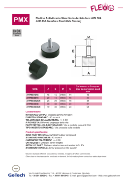
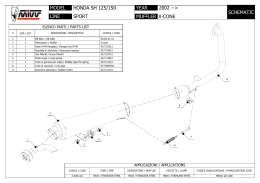
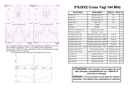
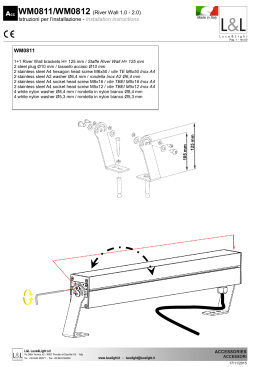
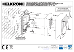
5JXX6 Yagi 50 MHz
Particolare
Chiave a brugola
Misura - Size
N
Inbuss tool
3 mm
1
Dado inox
Stainless steel nut
M4
5
Dado inox
Stainless steel nut
M6
1
Dado inox
Stainless steel nut
M5
2
Dado inox
Stainless steel nut
M8
4
Fascetta stringitubo inox
Hairpin
Stainless steel clamp
2
Hairpin
Isolatore
Isolatore
Isolatore dipolo con balun RG142
Piastra madre mast-boom
Qui di seguito vengono riportati i valori calcolati dal programma YO
6.52: sono riportati il guadagno, il R.O.S., il rapporto F/B ed impedenza.
Forward Gain, SWR, F/B ratio, Impedance, Polar and Rectangular Irradiation diagrams on E and H planes.
The following results have been calculated with YO 6.52
Description
1
Insulator
25 mm Ø
3
Insulator
30 mm Ø
1
Insulator dipole with RG142
25 mm Ø
1
Plate mast - boom
1
Rondella grover inox
Stainless steel grover washer
4 mm Ø
7
Rondella grover inox
Stainless steel grover washer
5 mm Ø
2
Rondella grover inox
Stainless steel grover washer
6 mm Ø
1
Rondella grover inox
Stainless steel grover washer
8 mm Ø
4
Rondella piana inox
Stainless steel plane washer
6 mm Ø
1
Rondella piana inox
Stainless steel plane washer
8 mm Ø
Semielemento 12 mm Ø
Sezione boom (nero - rosso)
Half element
4
10
Boom Section (black - red)
2000x30x2 mm
1
Sezione boom (nero)
Boom Section (black)
2000x25x1.5 mm
1
Sezione boom (rosso)
Boom Section (red)
1500x25x1.5 mm
1
Vite autofilettante inox
Stainless steel parker screw
3.5 x 9.5 mm
9
Vite TCE inox
Stainless steel bolt
M4 x 12 mm
2
Vite TCE inox
Stainless steel bolt
M4 x 20 mm
5
Vite TE inox
Stainless steel bolt
M5 x 35 mm
2
Vite TE inox
Stainless steel bolt
M6 x 35 mm
1
Vite TE inox
Stainless steel bolt
M8 x 35 mm
2
Vite TE inox
Stainless steel bolt
M8 x 90 mm
2
ATTENZIONE ! Non eccedere nel serraggio dei vari
dadi, stringere compatibilmente con i materiali di
costruzione impiegati
BEWARE ! Do not exceed on nuts used for antenna
assembly ! Just tighten them depending on materials
Montaggio - Assembly Instruction
1. Inserire gli isolatori come mostrato in Fig. A con vite TCE M4 x 20 mm.,
rondella e dado, senza serrare definitivamente.
Insert the insulators how show on Fig. A with screw TCE M4 x 20 mm.,
washer and nut, without clamp.
2. Unire il boom rispettando i colori, inserendo prima la fascetta stringitubo ed in seguito la
vite di fissaggio M5 x 40 mm.
con rondella e dado.
Combine the boom following
the coloured, put the stainless
steel clamp and screw M5 x 40
mm. through the boom with
washer and nut.
3. Inserire gli elementi come mostrato in Fig. A, rispettando i
numeri stampati.
Insert the insulators how show
on Fig. A, check the number
printed.
4. Inserire prima il semidipolo
maschio d’ogni elemento e
farlo arrivare a battuta
sull’isolatore, inserire poi la
femmina e fare in modo che i
fori coincidano, così da poter
fissare il tutto tramite vite autofilettante 3,5 x 12 mm.
In the first time insert male
semidipole into the insulator
and combine the holes with
female semidipole and insulator; fixed with parker screw
3,5 x 12 mm.
5. Allineare gli elementi, stringere
le viti a brugola M4 x 20 mm.;
per evitare rotazioni, forare con
una punta da 3 mm Ø (vedi foto) e bloccare con vite 3,5 x 12
mm.
Check the alignment of elements, clamp inbuss screws M4
x 20 mm., to avoid rotations
made one hole of 3 mm Ø (see
photo) and fixed it with screw
3,5 x 12 mm.
6. Rimuovere le viti a brugola M4 x
12 mm. sul dipolo, inserire i due
elementi, montare l’hairpin e
fissare il tutto mediante viti da
brugola M4 x 12 mm e rondella.
To combine the dipole remove
inbuss screws M4 x 12 mm., put
the semielements to combine
the holes, fixed with inbuss
screw M4 x 12 mm. and washer.
7. Montare la piastra di fissaggio tra boom e mast, come mostrato in foto;
trovando il baricentro dell’antenna con il cavo coassiale utilizzato.
Put the plate boom - mast , see on photo; find the baricentre with the coaxial cable included.
8. Montare l’antenna con gli isolatori rivolti verso il basso per evitare possibili
depositi d’acqua, neve o ghiaccio.
Put the antenna with the insulators under the boom, this solution avoind
water, snow and ice on the insulators.
www.i0jxx.com
[email protected]
Fig. A
1350
1
1350
1206
1340
1340
2
rosso - red
1350
3
1350
1207
1206
nero - black
1288
4
1288
1469
5
1469
1207
Scaricare