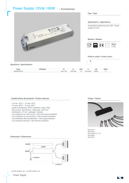
Corrosione
Memorie
FIELD TESTS ON THE CATHODIC PROTECTION
OF A SHIP PROPELLER SYSTEM
T. Bellezze, R. Fratesi, G. Roventi
The efficiency of the cathodic protection of a propeller system, installed in a large-medium sized ship, was
investigated. This system is constituted by a 17 4PH propeller shaft, concentrically mounted in an AISI 304
stern tube. Sea water is usually pumped in the interspace between these two metallic parts for cooling the
propeller system during navigation, but in the main part of the year it remains stagnant because the ship is
berthed in the harbour. Considering that such conditions determined critical localized corrosion phenomena on
the propeller system, in this work the efficiency of the cathodic protection, performed by plain steel anodes,
was tested. A real propeller system (about 3 m in length) was slightly modified for monitoring the potential in
different points by the use of local probes. Even the protection current was suitably monitored. The tests were
performed both with stagnant and with moving sea water up to a flow rate of 40 L/min, in order to find the
same conditions of the ship during navigation. From the experimental results, the efficiency of the cathodic
protection was good even if the circulating water with the higher flow rate represents a critical condition.
Parole chiave: Localized corrosion - Cathodic protection - Sacrificial anodes - Stainless steels - Sea water.
INTRODUCTION
The selection of the stainless steel alloys destined to
marine applications is a crucial step of the industrial
design process, where not only their mechanical properties
must be considered but also their localized corrosion
performances, taking into account the high aggressiveness
of sea water [1,2]. 17 4PH, a precipitation hardened
stainless steel, is good for both these characteristics [37]. It is a martensitic stainless steel with a 3 wt% of copper
which determines, together with chromium, the alloy
hardening thanks to the precipitation of these two metals
reach phases [7,8], during an ageing process carried out at
480-600 °C [3,4]. The precipitation process is commonly
carried out after a solubilization at about 1000 °C.
From a previous work [9], in some propeller shafts, crevice
and pitting corrosion were found in a relatively short
time. In particular, pitting on the metallic parts subject to
mechanical stress can determine the cracks initiation with
the subsequent failure. Considering the examined cases,
pitting corrosion was observed in the whole surface of the
shaft while crevice corrosion was found in correspondence
of rubber bearings, used for the installation of the shaft
concentrically inside the stern tube.
Some authors reported in the literature [10] similar
corrosion phenomena on AISI 316 propeller shafts. Both
this material and 17 4PH stainless steel are suitable for
T. Bellezze, R. Fratesi, G. Roventi
Dipartimento di Scienze e Ingegneria della Materia,
dell’Ambiente ed Urbanistica, Università Politecnica
delle Marche, Via Brecce Bianche, 60131 Ancona.
La Metallurgia Italiana - n. 5/2013
naval industry but the possibility of localized corrosion has
to be considered in any case.
17 4PH stainless steel is particularly prone to stress
corrosion cracking, both in those conditions where
hydrogen is generated (therefore, determining hydrogen
embrittlement like most high resistance steel) and in sea
water where the shaft failure was taken into consideration
[8]. Special attention must be paid to the selection of the
sacrificial anodes in cathodic protection, which must bring
a given metallic structure in protection conditions, without
reaching negative potentials sufficient to determine
hydrogen evolution. However, even when such negative
potentials are not reached, bringing 17 4PH to lower
potentials with respect to its corrosion potential could
produce a reduction of its mechanical performances [11].
In this work, the efficiency of cathodic protection performed
with plain carbon steel anodes was examined. This was the
strategy considered for eliminating the localized corrosion
phenomena found in the 17 4PH propeller shafts, excluding
the possibility of hydrogen evolution as well. For this aim,
the experimentation was performed in Ancona harbour on
a real propeller shaft-stern tube system, with a length a little bit more than 3 m and constituted respectively by 17
4PH and AISI 304 stainless steels. The protection currents
and the localized potentials were monitored using suitable
probes and a workstation. Sea water was collected directly
from the harbour mole by means of a pump.
EXPERIMENTAL PROCEDURE
A 17 4PH propeller shaft (f = 115 mm and length 4 m)
concentrically mounted in an AISI 304 stern tube (f = 163
31
Memorie
Fig. 1 - Scheme of the propeller system, modified for the installation of the suitable reference electrodes (in the
f 16 mm holes) and with the two plain steel anodes on the walls of the stern tube. Furthermore, sea water inlet
and outlet are shown. All measure numbers are in mm.
Fig. 1 - Illustrazione schematica del sistema asse e astuccio, con le modifiche per l’inserimento di opportuni elettrodi di
riferimento (nella serie di fori da 16 mm) e con i due anodi di acciaio comune opportunamente supportati sulla parete
dell’astuccio. Sono inoltre indicati i punti di ingresso e di uscita dell’acqua di mare. Tutte le misure sono in mm
mm and length 3.11 m) were both used for the present
experimentation as schematically shown in Fig. 1.
Along the whole stern tube length, 8 holes were made (f =
16 mm; they are visible in the upper side of Fig. 1) in order
to insert 7 Ag/AgCl/KCl sat. reference electrodes (E = -35
± -45 vs. SCE) and a SCE electrode (+0.241 V vs NHE), all
suitably built in laboratory for continuous monitoring of the
potentials at different points of the system. All potentials
measured in this work are reported with respect to SCE.
The local potential measurements, performed by these
probes, allowed the verification of cathodic protection
efficiency along the whole interspace.
In the diametrically opposite side, the seats for two plain
steel anodes, cylindrically shaped (f = 35 mm, length 70
mm), were obtained (Fig. 1). Initially, their position was
defined with respect to stern tube ends so as to have
the same distance from each of them and corresponding
to 1/4 of stern tube length; in this way, the cathodic
protection current can be distributed homogeneously
in the whole interspace between the two metallic parts.
However, due to ship specific design reasons, the anodes
were placed as shown in Fig. 1.
At the stern tube ends, two sluice valves were installed
respectively for water inlet and outlet. They gave the
possibility either to have a circulating water at a defined flow
rate or to maintain water in stagnant conditions. Adriatic
sea water (salinity 39 g L-1 and oxygen concentration
7-8 ppm [1,2]) has been collected by means of a pump
directly from the harbour mole. Thanks to the valves, the
flow rate for this experimentation was set at 20 L/min, 30
L/min and 40 L/min. This highest flow rate corresponds
approximately to that of the circulating water in the
propeller system during navigation.
During the assembly of the whole system, the shaft, the
stern tube and the anodes were electrically insulated.
They were connected electrically with a control board
which allowed the measure of the partial currents supplied
by the anodes with respect to both metallic parts to be
protected. A simplified electrical scheme of the circuit is
represented in Fig. 2, where also the reference electrodes
32
are shown. Finally, the shunt resistors (1 W), visible in Fig.
2, were used for continuous monitoring of partial currents
in all experimental conditions. The switches allowed the
direct observation of polarization effects during the tests.
The continuous monitoring of currents and potentials
were carried out by means of a Data Switch Unit
Agilent Technology Mod. 34970A where two multiplexer
modules 34901A were inserted: the first one for potential
measurements while the second one for partial current
measurements. The Unit was connected to a PC by a RS232 port for data storage at defined intervals of time.
At the beginning, for all test sessions, all switches of Fig. 2
were OFF for recording the free corrosion potentials of all
metallic parts of the studied system (Fig. 1). Subsequently,
they were sequentially switched ON in order to observe
the polarization effects produced by the anodes and then
to test the initial efficiency of the cathodic protection.
RESULTS AND DISCUSSION
Firstly, the tests were performed with circulating water in
the interspace between the shaft and the stern tube and
subsequently in stagnant water.
When the sea water flow rate was 20 L/min, the potential
trends corresponding to the different metallic parts, are
shown in Fig. 3. The polarization effect is pretty clear at
the activation of cathodic protection in correspondence
of the sudden variation of the shaft, the stern tube and
the anode potentials (see left side of Fig. 3). Gradually,
the system potential reached stationary values around
-0.350 V vs SCE, which corresponds to perfect passivity
conditions [9].
Fig. 4 shows the trend of the total cathodic protection
current with an initial peak of 0.065 A and with a subsequent
achievement of a stationary value around 0.045 A. Both
anodes supplied more or less the same amount of current,
as can be observed from the partial current curves, while
between the shaft and the stern tube, the first adsorbs
less current than the second one. This can be explained by
La Metallurgia Italiana - n. 5/2013
Corrosione
Fig. 2 - Scheme of the circuit
used for cathodic protection
tests. The symbols mean: PS
= propeller shaft; ST= stern
tube; ANi= anode, i=1,2; Agi =
Ag/AgCl reference electrode,
i=1,…,7; SCE = saturated
calomel reference electrode;
SW = switch.
Fig. 2 - Schema del circuito
utilizzato per la protezione
catodica. I simboli riportati
significano: PS = asse; ST =
astuccio; ANi = anodo, i=1,2; Agi
= elettrodo di riferimento Ag/
AgCl, i=1,…,7; SCE = elettrodo di
riferimento a calomelano saturo;
SW = interruttore
Fig. 3 - Potential trends in cathodic protection
conditions with circulating water at 20 L/min.
Fig. 3 - Variazione dei potenziali in condizioni di protezione
catodica con acqua circolante a 20 L/min.
Fig. 5 - Trends of the local potentials on the basis of
reference electrode positions (Fig. 2) in the case of
the test with circulating water at 20 L/min.
Fig. 5 - Variazione dei potenziali locali secondo la
disposizione degli elettrodi mostrata in Fig. 2. Prova di
protezione catodica con acqua circolante a 20 L/min.
La Metallurgia Italiana - n. 5/2013
Fig. 4 - Partial current trends (absolute values) in cathodic
protection conditions with circulating water at 20 L/min.
Fig. 4 -Variazione delle correnti parziali (in valore assoluto) in
condizioni di protezione catodica con acqua circolante a 20 L/min.
the higher active surface of the stern tube with respect to
that of the shaft (1.58 m2 vs. 1.12 m2).
Fig. 5 shows the potentials recorded by all reference
electrodes schematically illustrated in Fig. 2: from this
diagram, it is possible to conclude that the system is in the
perfect passivity condition in all parts, showing in this way
the efficiency of cathodic protection determined by both
anodes. Furthermore, the possible overprotection with
the consequent hydrogen evolution, which can determine
the 17 4PH embrittlement, can be excluded. In despite
of the low differences between each potential trend,
more negative values were measured from the reference
electrodes installed in the zones near to the anodes, where
polarization effect is higher, while more positive values
were recorded in the zones far from them (Ag1 and Ag7;
see Fig. 2 and Fig. 5).
Significant differences between the previous case and
the case of circulating water at 30 L/min were not
33
Memorie
observed. Therefore, for the sake of brevity, the currents
and potentials relative to this case are not reported here.
However, the cathodic protection was guaranteed from
both anodes.
On the contrary, the case of the circulating water at 40
L/min was significantly different, because it determines a
turbulent water flow with the clear presence of air bubbles
in the fluid running in the interspace of the propeller system.
This determines the presence of a high concentration of
oxygen on the surface of metallic parts which contributes
to increase their potentials both with and without cathodic
protection (Fig. 6). However, such an increase of the
corrosion potential could mainly be attributed to the
formation of biofilms on the metal surface [12], which is
quite normal in sea water exposure as that observed in
this work. The increase of the stainless steel corrosion
potential determines an increase in its own susceptibility
to localized corrosion. In fact, in these conditions, the risk
of pitting corrosion of 17 4PH stainless steel is present,
due to the achievement of potential values above the
pitting potential of this material with circulating sea water
(Epit = 0,074 V vs SCE [9]). Therefore, cathodic protection
is essential in this situation.
Switching on the cathodic protection, the potential of the
shaft reached values in the range -0,040 and +0,030 V vs
SCE, where higher values correspond to the zones far from
the anodes (measured by Ag1, Ag2 and Ag7 reference
electrodes; their trends are not reported here). Therefore,
in these conditions, the cathodic protection is essential
to avoid the risk of localized corrosion process in the
propeller system.
Concerning the total current trend, after the initial peak
determined by the protection switching on event, it reaches
values quite high in comparison with those reached in the
cases of circulating water at 20 and 30 L/min. In fact, with
flow rate at 40 L/min, the quasi-stationary conditions are
reached at 0.095 A. The higher current measured in this case
with respect to those measured previously is determined
by the significant increase of the stern tube and shaft
corrosion potentials with respect to the anode corrosion
potentials (compare Fig. 3 in the left side and inset of the
Fig. 6). This produces an increase of electromotive forces
of the galvanic couple plain steel-stainless steel with the
consequent increase of the protection current.
In conclusion, in the case of the system with stagnant
water, potential and current trends were rather different
from those recorded with circulating water. In fact, without
sea water renewal, oxygen consumption determined
by cathodic protection produces the decrease of its
concentration. As a consequence, a gradual decrease of the
total protection current is observed with the achievement
of very low values close to 0 A, after 40-50 hours (Fig.
7). This behaviour is not surprising taking into account
that the protection current is strictly related to the limit
diffusion current of oxygen, whose value is influenced by
its concentration in the water, by the water temperature,
flow rate and turbulence [1]. Considering that the water
is stagnant and the oxygen is consumed by the metallic
34
Fig. 6 - Potential trends in condition of the circulating
water at 40 L/min. Inset: magnification of the diagram
at early time periods.
Fig. 6 - Variazione dei potenziali in condizioni di protezione
catodica con acqua circolante a 40 L/min. Inserto:
ingrandimento del grafico a valori bassi di tempo.
parts of the propeller system during cathodic protection,
its concentration tends to decrease and as a consequence
its limit diffusion current tends to decrease.
Of course, even the potentials measured with stagnant
water were different, if compared to those recorded with
circulating water (the diagram is not reported for a sake
of brevity); they tends to decrease contemporarily for all
metallic parts up to the achievement of -0.650 V vs SCE,
which corresponds to the perfect passivity condition.
Furthermore, at these potential values, there is neither the
evolution of hydrogen nor the consequent risk of stainless
steel embrittlement.
The current supplied by plain steel anodes and measured
after experimental tests can be used to calculate their
durability and to program their substitution.
The consumption of an anode can be determined
considering the current supplied in quasi-stationary
conditions using the following equation:
(1)
where MFe represents the anode consumption in g/day,
I represents the quasi-stationary current supplied and h
represents the anode dissolution efficiency.
Considering the average of the stationary current
supplied by both anodes, more or less in equal amounts,
and considering h =1, from equation (1), the average
consumption of an anode can be calculated obtaining the
values showed in Table 1.
In conclusion, taking into account the consumption data of
the previous Table 1 and the anode dimensions (Ø35x70
mm), its theoretical life time can be obtained as shown in
Table 2.
Considering that the propeller system studied in this work
is relative to yachts, a hypothesis of their use during a
La Metallurgia Italiana - n. 5/2013
Corrosione
Iaverage
MFe
(A)
(g/day)
Circulating water
at 20 L/min
0.023
0.575
Circulating water
at 30 L/min
0.024
0.599
Circulating water
at 40 L/min
0.046
1.149
Stagnant water
after 20 hours
0.011
0.274
Stagnant water
after 50 hours
0.001
0.025
Test conditions
Fig. 7 - Partial current trends (absolute values) in
cathodic protection conditions with stagnant water.
Fig. 7 - Variazione delle correnti parziali (in valore assoluto)
in condizioni di protezione catodica con acqua stagnante.
year can be made: for the main part of their life, they are
berthed to a mole and, for the remaining time, they are
sailing, in particular during summer. Therefore, a possible
hypothesis of the yacht use is three months (90 days) of
sailing with circulating water at a flow rate of 40 L/min
while for the remaining 9 months (365-90 = 275 days) in
the condition of “stagnant water after 50 hours” (see Table
1).
With reference to the values reported in Table 1, the annual
consumption of an anode will be:
(2)
Therefore, the anode time life in these conditions will be:
(3)
Finally, in the present hypothesis, it can be suggested that
it is necessary to substitute the anodes after about 4 years
of the yacht use.
CONCLUSIONS
In this work, experimental tests were performed for
studying the cathodic protection efficiency obtained by
the use of sacrificial plain steel anodes with respect to
a propeller shaft-stern tube system, installed in largemedium sized ships and subject to localized corrosion.
For this aim, a monitoring workstation was organized for
measuring the currents and the potentials.
From the results, in the presence of cathodic protection,
the whole system showed potential values under the
repassivation potential of all materials, in almost all
conditions tested in this study and therefore the localized
La Metallurgia Italiana - n. 5/2013
Tab. 1 - Summary of the average consumption of an
anode in grams per day.
Tab. 1 - Riepilogo del consumo medio di un anodo
espresso in grammi al giorno.
Test conditions
Life time
(days)
(months)
Circulating water
at 20 L/min
920
30
Circulating water
at 30 L/min
882
29.5
Circulating water
at 40 L/min
460
15
Stagnant water
after 20 hours
1925
64
Stagnant water
after 50 hours
21180
706
Tab. 2 - Summary of anode life time in different
conditions, given both in days and in months
Tab. 2 - Riepilogo della durata di un anodo, espressa sia in
giorni sia in mesi.
corrosion can be excluded. With more details, in stagnant
water, the potentials reached low values but sufficiently
high to avoid the hydrogen evolution which can produce
the dangerous steel embrittlement. In moving water, with a
flow rate of 40 L/min, the system was found in a condition
of localized corrosion risk. Furthermore, in this case a
presence of biofilms on the metal surface was observed.
Particular attention must be paid to this phenomenon
which increases the steel corrosion potential and, as a
consequence, it increases its susceptibility to localized
corrosion. Therefore, in these conditions, cathodic
protection is essential.
In a first approximation, a theoretical calculation of the
35
Memorie
durability of an anode was done: 4 years and 9 months.
This result was obtained hypothesizing for a yacht a period
of inactivity of 9 months and a period of sailing activity
for the remaining 3 months, during a year. Practically, the
anodes substitution could be done after 4 years.
REFERENCES
[1] L. LAZZARI, P. PEDEFERRI, “Cathodic Protection”, Polipress, Milan,
Italy (2000).
[2] W. VON BAECKMANN, W. SCHWENK, W. PRINZ (EDS.), Handbook
of Cathodic Corrosion Protection, Theory and Practise of
Electrochemical Protection Processes, third ed., Gulf Publishing
Company, Houston, Texas (1997).
[3] G. Di Caprio, Gli acciai inossidabili, Hoepli, Milano (2003).
[4] M. Karaminezhaad, S. Sharafi, K. Dalili, J. Mater. Sci., 2006,
41, 3329-3333.
Corrosione
[5] R. L. Liu, M.F. Yan, D.L. Wu, J. Mater. Processing Technol., 2010,
210, 784-790.
[6] M. Esfandiari, H. Dong, Surf. Coat. Technol., 2007, 202, 466478.
[7] I. Costa, C.V. Franco, C.T. Kunioshi, J.L. Rossi, Corrosion,
2006, 62, 357-365.
[8] C. Fahir Arisoy, Gokhan Basman,
M. Kelami sesen,
Eng.
,
, ,
Failure Analysis, 2003, 10, 711-717.
[9] T. Bellezze, M. Malavolta, R. Fratesi, Atti della IX edizione delle
GIORNATE NAZIONALI SULLA CORROSIONE E PROTEZIONE, Villa
Mondragone - Monte Porzio Catone (Roma), 6-8 luglio 2011, CDROM a cura dell’ASSOCIAZIONE ITALIANA DI METALLURGIA, Milano
(2011).
[10] D.R. Lenard, J.G. Moores, Corrosion, 1993, 49, 769-775.
[11] B. G. Allen, R. H. Heidersbach, S. F. Mealy, 12th Annual Offshore
Technology Conference, Houston, Tex., May 5-8,1980, paper OTC
3856.
[12] M.V. Biezema, Microbial Corrosion, European Federation of
Corrosion Publications N. 29, IOM Communications Ltd., London
(2000), 36-46.
Prove in campo dell’efficacia della protezione catodica
in un sistema di propulsione di una nave
Parole chiave: Corrosione localizzata - Protezione catodica - Anodi sacrificali - Acciai inossidabili - Acqua di mare
La presente ricerca ha riguardato l’analisi dell’efficacia della protezione catodica di un asse portaelica del motore di
imbarcazioni medio-grandi. L’asse è di acciaio inossidabile 17 4PH indurito per precipitazione, inserito in un astuccio
cilindrico di acciaio inossidabile AISI 304. Nell’intercapedine tra i due componenti si trova acqua di mare, che risulta
stagnante per la maggior parte del tempo, poiché le imbarcazioni considerate (yacht) restano ferme in acqua per circa
nove mesi all’anno. Tenendo conto che in simili condizioni, più di un asse ha dato luogo a preoccupanti fenomeni di
corrosione localizzata, in questo lavoro è stata verificata l’efficacia della protezione catodica utilizzando anodi sacrificali
di acciaio dolce come metodo preventivo per evitare tale tipo di corrosione. La sperimentazione è stata eseguita su un
sistema asse-astuccio di dimensioni reali (di lunghezza di poco superiore ai 3 metri) a cui sono state apportate delle
modifiche per permettere il monitoraggio dei potenziali e delle correnti in gioco, al fine di effettuare la valutazione
oggetto del presente studio. I test sono stati effettuati sia con acqua di mare stagnante, che con acqua fatta circolare
con varie portate fino a 40 L/min per simulare le condizioni che si hanno in fase di navigazione.
Dai risultati ottenuti, è emerso che tutto il sistema, quando la protezione era attiva, si trovava al di sotto dei potenziali di pitting
relativi ai materiali che lo costituiscono, quindi risultava essere escluso un innesco della corrosione di questo tipo. L’uso di anodi di
acciaio comune portava il sistema a valori di potenziale che dipendevano dalle condizioni operative in cui esso si trovava a lavorare
e, in quasi tutte le prove realizzate, esso si trovava a potenziali inferiori rispetto a quello di ripassivazione e quindi in condizioni di
passività perfetta, che sono appunto le migliori per prevenire i fenomeni corrosivi localizzati. In condizioni di acqua stagnante si
raggiungevano valori di potenziale più bassi rispetto al caso di acqua circolante ma, fortunatamente, non si arrivava a valori tali
da permettere lo sviluppo di idrogeno, che può indurre all’infragilimento dell’asse, trattandosi di un acciaio ad alta resistenza e
pertanto, come altri materiali di questo tipo, soggetto a tale fenomeno. Di contro, in condizioni estremamente ossigenate (40 L/
min), il potenziale del sistema tendeva ad innalzarsi e ad avvicinarsi addirittura al potenziale di pitting. La maggiore ossigenazione
dell’acqua non è stata probabilmente la principale causa dell’innalzamento del potenziale, osservato in queste condizioni, per il
sistema in studio, poiché a questo risultato sperimentale ha contributo la formazione di una certa quantità di biofilm sulle superfici
dei metalli testati. Esso produce le condizioni specifiche che conducono all’innalzamento dei potenziali di corrosione degli acciai
inossidabili come quelli testati, aumentando in modo critico la probabilità di corrosione localizzata. Proprio per ridurre tale probabilità,
si rende indispensabile l’impiego della protezione catodica per il sistema oggetto di questo studio.
È stato eseguito infine il calcolo teorico approssimativo della durata di un anodo. Il valore determinato, di 4 anni e 9
mesi, potrebbe risultare relativamente attendibile poiché è stato ottenuto ipotizzando una storia di navigazione annua
in cui l’imbarcazione rimane attraccata in banchina per nove mesi, mentre per i restanti tre mesi risulta sempre in
navigazione. In pratica, gli anodi potrebbero essere sostituiti dopo 4 anni.
In fase di progettazione, oltre a studiare forme e dimensioni che consentano di massimizzare la durata dell’anodo,
vanno anche studiati dei sistemi che ne permettano il cambio in modo agevole ed economico.
36
La Metallurgia Italiana - n. 5/2013
Scarica