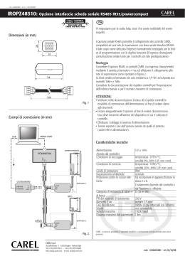
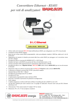
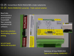
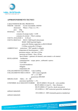
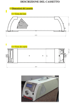
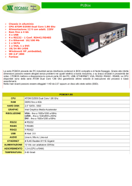
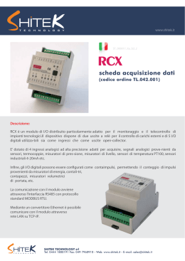
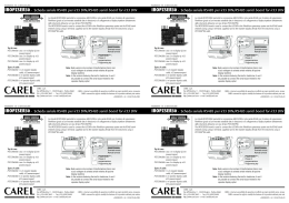
cod. +050000161 rel.1.0 - 11.02.2005
HYSC00F0P0 Scheda seriale RS485 per e-drofan / e-drofan RS485 serial card
LEGGI E CONSERVA
QUESTE ISTRUZIONI
READ AND SAVE
THESE INSTRUCTIONS
Dimensioni terminale / Terminal dimensions
Vi ringraziamo per la scelta fatta, sicuri che sarete soddisfatti del vostro
acquisto.
Thank you for having chosen this product. We trust you will be satisfied
with your purchase.
Scheda seriale per collegamento ad una rete RS485
Serial board for connection to a RS485 network
L’opzione HYSC00F0P0 consente il collegamento, attraverso un’interfaccia
elettricamente NON optoisolata, dell’e-drofan ad una rete RS485 tramite un
connettore a morsetti estraibili presente sulla scheda.
Grazie alla scheda seriale RS485 è possibile realizzare sistemi di supervisione
personalizzati.
Con questo stesso accessorio è possibile l’integrazione dell’e-drofan in sistemi basati
su Modbus®.
The HYSC00F0P0 option enables connection of the e-drofan, via an electrically non
opto-insulated interface, to an RS485 network via a connector with removable
terminals on the board.
With the RS485 serial board, you can build customised supervision systems.
This accessory can also be used for integrating e-drofan into systems based on the
Modbus®.
Istruzioni per il montaggio e l’installazione
Assembly and installation instructions
morsetto
GND, RX+/TX+, RX-/TX- :
connettore:
terminal
GND, RX+/TX+, RX-/TX-:
connector:
3,1
6
Fig. 1
connettore 7 vie:
I significati dei pin su tale connettore sono evidenziati nella Fig. 3 ed elencati in Tab. 1.
Montaggio su fan coil / Mounting on fan coil
1
2
3
4
significato
connessione RS485
prelievo alimentazione e comunicazione con il controllo
elettronico 8 vie da inserire nella rete RS485 (e-drofan)
destinato ad usi futuri
7-way connector:
meaning
RS485 connection
power offtake and communication with the 8-way
electronic control to be inserted in the RS485 network
(e-drofan)
for future use
The meanings of the pins on this connector are shown in Fig. 3, and listed in Table 1.
Avvertenze. Precauzioni nel maneggiare la scheda
I danneggiamenti elettrici che si verificano sui componenti elettronici avvengono quasi
sempre a causa delle scariche elettrostatiche indotte dall’operatore. È quindi
necessario prendere adeguati accorgimenti per queste categorie di componenti, ed in
particolare:
• prima di maneggiare qualsiasi componente elettronico o scheda, toccare una
messa a terra (il fatto stesso di evitare di toccare un componente non è sufficiente
in quanto una scarica di 10000 V, tensione molto facile da raggiungere con
l’elettricità statica, innesca un arco di circa 1 cm);
• i materiali devono rimanere per quanto possibile all’interno delle loro confezioni
originali. Se necessario, prelevare la scheda da una confezione e trasferire il
prodotto in un imballo antistatico senza toccare il retro della scheda con le mani;
• evitare nel modo più assoluto di utilizzare sacchetti in plastica, polistirolo o spugne
non antistatiche;
• evitare nel modo più assoluto il passaggio diretto tra operatori (per evitare fenomeni
di induzione elettrostatica e conseguenti scariche);
• effettuare tutte le operazioni di installazione e manutenzione a macchina non
alimentata;
• utilizzare cavi schermati per le connessioni seriali: 2 cavi + schermo, non effettuare
connessioni a stella (utilizzare connessioni a catena);
• connettere lo schermo al morsetto GND e inserire le due resistenze di terminazione
da 120 ohm agli estremi della rete RS485 (Fig.5);
• la scheda seriale non è optoisolata, ogni dispositivo deve essere alimentato da un
trasformatore dedicato e non deve essere effettuata la connessione a terra.
Nell’e-drofan il trasformatore è già integrato all’interno della scheda.
Fig. 2
Warnings. Precautions for handling the board:
Electrical damage to the electronic components almost always happens due to
electrostatic discharges induced by the operator.You must therefore take adequate
precautions for these categories of components, specifically:
• before handling any electronic component or board, touch an earthing connection
(avoiding to touch a component is not enough, because a 10,000 V discharge, very
easy to reach with static electricity, triggers an arc of about 1 cm);
• the materials must, if possible, remain inside their original packs. If necessary, take
the board from a pack and transfer the product into an antistatic pack, without
touching the back of the board with your hands;
• do not, on any account, use plastic bags, polystyrene or antistatic sponges;
• absolutely avoid direct transfer among operators (to avoid electrostatic induction
leading to discharges);
• carry out all installation and maintenance operations with the machine powered
down;
• use screened cables for the serial connections:2 cables + screen, do not make star
connections (use chain connections);
• connect the screen to the GND terminal and fit the two 120 ohm termination
resistors at the ends of the RS485 network (Fig.5);
• the serial board is not opto-insulated. Each device must be powered by a dedicated
transformer and the earth connection must not be made. In the e-drofan, the
transformer is already integrated inside the board.
Pin-strip
Technical specifications
Caratteristiche tecniche
pin
1
2
3
1 2 3
significato
meaning
GND
RX+/TX+
RX-/TXTab. 1
Fig. 3
Schema di collegamento / Connection diagram
sezione del cavo:
isolamenti:
condizioni di funzionamento:
condizioni di stoccaggio:
grado di inquinamento:
grado di protezione:
cat. di resistenza al calore e
al fuoco:
PTI dei materiali di isolamento:
periodo delle sollecitazioni
elettriche delle parti isolanti:
dimensioni (mm):
8…38 Vdc;
massima potenza assorbita: 250 mW
usare cavo ritorto e schermato a due fili
AWG20/22 con sezioni, ai morsetti di
mm2: min. 0,2 - max. 2,5
scheda non optoisolata
0T60 °C, umidità <90% U.R. non condensante
- 20T80 °C, umidità 80% U.R. non condens.
normale
IP00
D
tutti i materiali hanno PTI≥250
lungo
60x31x10, (60x31: scheda; 10: larghezza
componenti)
power supply
cable diameter:
insulation:
operating conditions :
storage conditions :
degree of pollution:
protection class:
heat and fire resistance
category
PTI of insulation materials:
period of electric stresses
of the insulating parts:
dimensions (mm):
8…38 Vdc;
maximum absorbed power: 250 mW
use a twisted, screened cable with two wires
AWG20/22 of 2 mm diameter at the terminals
mm2: min. 0.2 - max. 2.5
board not opto-insulated
0T60 °C, humidity <90% R.H non condensating
- 20T80 °C, humidity 80% R.H. non condens.
normal
IP00
D
all materials have PTI≥250
long
60x31x10, (60x31: board; 10: width of components)
GND
T+
T-
CVSTDUM0R0
alimentazione
GND
T+
T-
I/O BOARD
1..
GND
T+
T-
I/O BOARD
...n
Fig. 4
CAREL S.p.A.
Via dell’Industria, 11 - 35020 Brugine - Padova (Italy)
Tel. (+39) 0499716611 – Fax (+39) 0499716600
http://www.carel.com – e-mail: [email protected]
CAREL si riserva la possibilità di apportare modifiche o cambiamenti ai propri prodotti senza alcun preavviso.
CAREL reserves the right to modify the features of its products without prior notice.
cod. +050000161 rel.1.0 - 11.02.2005
Scaricare