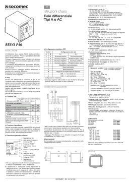
Via Como,55 Cairate (VA) Italy
RELE’ DIFFERENZIALE DI TERRA
Art. MRCD30DS
Schema di collegamento
Type A
10A 250V
resistive load
C NC NO
7 8 9 11 12 14
1 2 3 4 5 6
1
2
TOR
N
L1
L2
Power Supply
230V~
L3
CARATTERISTICHE TECNICHE E FUNZIONALI
Il relè differenziale di terra é costituito da un relè amperometrico e da un trasformatore toroidale riduttore di corrente.
Trovano impiego in reti BT con corrente alternata per sistemi TT e TNS , assicurando la protezione da contatti indiretti, complementare contro
contatti diretti, e contro i rischi di incendio (in quanto le corrente modeste verso terra non riescono a far intervenire il dispositivo di massima corrente,
magnetotermico).
Tutti i conduttori della linea monofase o trifase compreso il neutro, devono attraversare il toroide in modo che rilevi la corrente residua risultante; il
dispositivo interviene quando, per difetto d'isolamento, la somma vettoriale delle correnti nei conduttori passanti all'interno del toroide evidenzia una
risultante differenziale.
La soglia di intervento é impostabile mediante un minidip posto sul fronte ( 6 Parametri), analogamente al tempo di intervento (5 tempi).
Il relè di uscita é dotato di contatto in scambio libero da tensione.
Il riarmo (RESET) del dispositivo é manuale mediante un pulsante posto sul fronte dell'apparecchio; o togliendo alimentazione al dispositivo.
Sul fronte tramite il pulsante di TEST, vi é la possibilità di testare il relè differenziale.
Possibilità di piombare il frontale al fine di non permettere la manipolazione delle impostazioni.
Il relè differenziale è di tipo A , cioè garantisce il suo intervento in caso di corrente di dispersione alternata e o con componenti di dispersione pulsanti
ben specificate.
Il relè differenziale è considerato come protezione addizionale e quindi in aggiunta alle misure di protezione indicate dalla Norma di riferimento
CEI 64-8, e non come unico mezzo di protezione contro i contatti diretti.
Tensione di alimentazione
Classe di isolamento
Grado di protezione Frontale
Grado di protezione
Autoconsumo
Temperatura max del piano d'appoggio
Tensione di prova
Segnalazioni
Fault Led Rosso
Segnalazioni
On
Led Verde
Pulsante
Reset
Pulsante
Test
Uscite
Norme di riferimento
Circuito Amperometrico
230V+/-10% 40/60Hz
II
IP40
IP20
1.5W
55°C
2kV a 50Hz per 1 minuto (1kV per il circuito di misura)
Stato di intervento, Superamento della soglia, dopo il tempo di ritardo
Dispositivo correttamente alimentato
Azzeramento anomalia
Controllo funzionamento dispositivo
relè di scambio NC C NO 10A 250V
relè di uscita allarme NON in sicurezza attiva in quanto nel caso di
mancanza di tensione è impossibile ripristinare il Relè differenziale
EN 60947-2/B
CEI 64.8
EN 61010-1
conduttori: Lunghezza max 20mt, sezione minima 1.5mmq
Nelle immediate vicinanze, del circuito amperometrico, non devono esserci componenti elettromeccanici o grossi conduttori
di potenza per evitare che queste fonti di campi magnetici o di disturbi siano fonte di variazioni transitorie del segnale misurato.
Nel caso non sia possibile evitare questi disturbi, avvolgere tra di loro i conduttori del segnale amperometrico con l'utilizzo di
cavo schermato e con schermo collegato a terra.
Temperatura di funzionamento
Temperatura di immagazzinaggio
Dimensioni
DS_02250-30_02_IE
-10°C +55°C
-20°C +80°C
3 Moduli , DIN
1/4
RELE’ DIFFERENZIALE DI TERRA
Art. MRCD30DS
Via Como,55 Cairate (VA) Italy
CARATTERISTICHE TECNICHE E FUNZIONALI
Il trasformatore toroidale deve essere attraversato nel medesimo senso da tutti i conduttori attivi della linea, compreso
il neutro.
Mantenere i conduttori attivi il più possibile al centro del toroide ed eventualmente fascettarli insieme.
Nel caso in cui la linea protetta abbia un'armatura metallica A, questa deve essere collegata a terra a valle del toroide.
Toroide
Nel caso il toroide sia montato a valle del manicotto terminale, il
collegamento di terra DEVE attraversare il toroide ed il manicotto deve
essere isolato dal telaio di supporto, in questo modo la corrente di
terra circola solo nel collegamento di terra che attraversa il toroide
(altrimenti nel caso di guasto d'isolamento del cavo verso l'armatura
esterna del manicotto, la corrente di terra annulla la corrente
differenziale, non facendo intervenire il relé differenziale).
Se il toroide è installato a monte del manicotto terminale del cavo
armato, (attraversato solo dai conduttori attivi), il collegamento di terra
del manicotto non deve attraversare il trasformatore toroidale.
Nel caso di utilizzo di trasformatori toroidali apribili, occorre accertarsi,
prima di richiuderlo, che le superfici di contatto del nucleo siano
perfettamente pulite e che durante il serraggio le viti di accoppiamento
vengano serrate alternativamente a più riprese, in modo da ottenere
un accoppiamento equilibrato.
A
Armatura metallica
manicotto
A
Toroide
Toroide a valle
dell’armatura A
Toroide a monte
dell’armatura A
Impostazione della corrente di intervento e dei tempi
DELAY t(s)
Bytronic
MRCD30DS
ON
Fault
Type A
Delay
CURRENT I∆n
sec
Reset
Test
0
1
3
2
30 mA
300 mA
500 mA
1 A
3 A
30 A
654321
OFF
ON
30 mA
300 mA
500 mA
1A
3A
30A
4
0 sec
1 sec
2 sec
3 sec
4 sec
Durante l’operazione di impostazione il relè NON deve essere alimentato
63
58
Dimensioni in mm
85
52,5
45
69,2 85
35
49
8,5 8,5 8,5 8,5 8,5
DS_02250-30_02_IE
Peso: 0,26kg
2/4
Via Como,55 Cairate (VA) Italy
EARTH LEAKAGE RELAYS
Art. MRCD30DS
Connection diagram
Type A
10A 250V
resistive load
C NC NO
7 8 9 11 12 14
1 2 3 4 5 6
1
2
TOR
N
L1
L2
Power Supply
230V~
L3
TECHNICAL CHARACTERISTICS
Earth Leakage control and monitoring consist of a Current Relay and associated Summation Toroidal Current Transformer which are used in LV
networks with alternating current in TT and TNS systems. They provide the protection required against indirect contacts, (complementary
protection against direct contacts)and against the risk of fire ( as the low currents through the earth are not enough for to let the magnetothermic
device intervene).
All cables of a single or three phase system, including the neutral where present, must cross the toroid which is the point of
residual current,the device activates when it detects defective insulation which is indicated when the vectorial sum of the current carrying cables
results in a differential figure.
Current adjustment is selectable by means a minidip situated on the front of the instrument (6 parameters) as well as the time delay adjustament (5
parameters).
Output relay is a change-over contact.
The RESET is manual by means a button situated on front of instrument; or cutting the power supply.
TEST button is also situated on front of the instrument.
Sealable front. The TEST and RESET buttons are accessible with sealed front window also.
The presence on label of the symbol
means that the instrument is a differential type AC, not a unique device for protection against the
direct contacts.
Auxiliary power supply
Insulation class
Protectionclass in front
Protection class
Burden
Max temperature
Isolation test
Signalling Led
Signalling Led
Push
Push
Output
Standards
Fault Led Rosso
On
Led Verde
Reset
Test
230V+/-10% 40/60Hz
II
IP40
IP20
1.5W
55°C
2,kV a 50Hz for 1 min (1kV for the measurement circuit)
Working relay, over-limitis after the time delay
Device correctly supplied
Reset of anomaly
Test for control of the correct functions
one change-over contact NC C NO 10A 250V
Output relay NOT in active safety, as in case of adsence of voltage it
is impossible to restore the earth leakage relay.
EN 60947-2 / B
EN 61010-1
Ammetric circuit
Wires: lenght max 20m, section min. 1.5mmq
The cables cannot be installed in proximity of electromechanical components or power cables that can be source a of magnetic
fields and perturbation of measurement signal.
In very critical cases it is necessary to install a ferromagnetic sleeve around the cables in the intern of the toroid
The toroid must be crossed ,in the same sense by all the active cables of the line, neutral included (if present).
The neutral cable must not connected to the earth after the toroid
-10°C +55°C
Temperature operating
Temperature of storage
-20°C +80°C
Dimensions
3 DIN modules
DS_02250-30_02_IE
3/4
EARTH LEAKAGE RELAYS
Art. MRCD30DS
Via Como,55 Cairate (VA) Italy
TECHNICAL CHARACTERISTICS
These current transformers are for applications using Earth Leakage Relays. They consist of a high quality magnetic core
which detects fault currents, even of very low values.
The connection toroid-earth leakage relay must be effected with shielded cables in the following cases:
a) Differential threshold < 100mA
b) Distances of toroid > 10m
c) Signal cable installed at less than 30cm from the power cables
Toroid
It is advisable and, in critical situations, obligatory:
a) Make a plait with the connection cables toroid-relay
b) The section of the cables must be not less than 1mmsquare) and their
Metallic shell
A
A
lenght cannot exceed 20m
Coupling
c) The cables cannot be installed in proximity of electromechanical
components or power cables that can be source a of magnetic fields and
Toroid
perturbation of measurement signal
In order that the measurement of the toroid is correct, it is necessary:
a) Put the cables in the center of the toroid
b) The toroid must be not positioned in proximity of a curve zone of the
cables that cross it
c) Use a toroid with an internal diameter at least double the diameter of
the cable or of the plait of cables.
d) In very critical cases it is necessary to install a ferromagnetic sleeve
around the cables in the intern of the toroid
e) The toroid must be crossed ,in the same sense by all the active cables
of the line, neutral included (if present).
Toroid under
Toroid above
The neutral cable must not connected to the earth after the toroid
the coupling A
the coupling A
f) In case that the protected line has a metallic protection, it must be
connected to the earth, after the toroid
In case of use of split core toroids, be sure, before to close them that the contact surfaces of the core are perfectly cleaned
and that the fixing screws are very well fixed.
Toroidal ratio 50/0,1 – Number of turns: 500
Terminal covers included
Current adjustment and the time delay adjustament
DELAY t(s)
Bytronic
MRCD30DS
ON
Fault
Type A
Delay
CURRENT I∆n
sec
Reset
Test
0
1
3
2
30 mA
300 mA
500 mA
1 A
3 A
30 A
654321
OFF
ON
30 mA
300 mA
500 mA
1A
3A
30A
4
0 sec
1 sec
2 sec
3 sec
4 sec
During the adjustaments, the relay must be NOT connectes with the auxiliary supply
63
58
Dimensions in mm
85
52,5
45
69,2 85
35
49
8,5 8,5 8,5 8,5 8,5
DS_02250-30_02_IE
Weight: 0,26kg
4/4
Scaricare