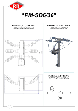
SD6/L
INTERRUTTORE DI MANOVRA-SEZIONATORE
SWITCH-DISCONNECTOR
1 – Isolatore
2 – Attacco superiore
3 – Attacco inferiore
4 – Calotta solo per 24kV
5 – Involucro in acciaio inox
6 – Scatola comandi
7 – Comando IMS
8 – Comando ST
9 – Oblò d’ispezione
10 – Blocco a chiave
11 – Manometro
12 – Dispositivo assenza presenza tensione
13 – Valvola di sicurezza
1 – Insulator
2 – Upper terminal
3 – Lower terminal
4 – Electrical field adapter only for 24kV
5 – Stainless steel body
6 – Operating mechanisms box
7 – Switch-disconnector operating seat
8 – Earthing-switch operating seat
9 – Inspection window
10 – Key interlock
11 – Manometer
12 – Voltage signalling lamps
13 – Safety valve
CARATTERISTICHE DEI COMPONENTI
CHARACTERISTICS OF COMPONENTS
L’unità di sezionamento isolata in SF6 è equipaggiata
con un interruttore di manovra-sezionatore e un
sezionatore di terra con comandi separati ed
interbloccati.
SF6 disconnecting unit is equipped with switchdisconnector and earthing switch fitted with separated
and interlocked operating mechanism.
SD6/L
CARATTERISTICHE TECNICHE
TECHNICAL FEATURES
GRANDEZZE NO MINALI / RATED VALUES
Te nsione nominale
Rated nominal voltage
Frequenz a nominale
Rated nominal frequency
Te nsione di prova 1 min. 50 Hz verso terra e fra le fasi
Test voltage 1 min. 50 Hz against earth and between the phases
Te nsione di prova 1 min. 50 Hz tra i contatti aperti dell’ IMS
Test voltage 1 min. 50 Hz between the switch-disconnector opened contacts
Te nsione di manovra ad impulso verso terra e fra le fasi
Impulse withstand voltage against earth and between the phases
Te nsione di manovra ad impulso tra i contatti aperti dell’IMS
Impulse withstand voltage between the switch-disconnector opened contacts
Corrente nominale
Rated nominal current
Potere di interruzione nominale carico prevalentemente attivo
Rated breaking capacity m ainly active load
Potere di interruzione nominale trasformatori a vuoto
Rated breaking capacity no-load transformer
Potere di interruzione nominale linee a vuoto
Rated breaking capacity no-load overhead lines
Potere di interruzione nominale cavi a vuoto
Rated breaking capacity no-load cables
Corrente ammissibile nominale di breve durata (1 se c.)
Rated short-tim e withstand current (1 sec.)
Corrente ammissibile nominale di breve durata (3 se c.)
Rated short-tim e withstand current (3 sec.)
Valore di cresta della corrente ammissibile nominale
Rated peak withstand current
Potere di stabilime nto
Making capacity
Ciclo di omologazione secondo le norme IEC
IEC standard test cycle
Numero di manovre me ccaniche
Endurance operation test (cycles)
* 25 kA-2 sec. a richiesta
* 25 kA-2 sec. on request
[kV]
12
17,5
24
[Hz]
50/60
50/60
50/60
[kV]
28
38
50
[kV]
32
45
60
[kV]
75
95
125
[kV]
85
110
145
400/630/800
400/630/800
[A] 400/630/800
[A]
400/630
400/630
400/630
[A]
6,3
6,3
6,3
[A]
10
10
10
[A]
16
16
16
[kA]
12,5-25*
12,5-25*
12,5-25*
[kA]
12,5-21
12,5-21
12,5-21
[kA]
31,5-65
31,5-65
31,5-65
[kA]
31,5-65
31,5-65
31,5-55
E1-E3
E1-E3
E1-E3
5000
5000
5000
SD6/L
DIMENSIONI D’INGOMBRO E INSTALLAZIONE
OVERALL AND INSTALLATION DIMENSIONS
Fori per fissaggio IMS in quadro *
Quote blocco porta *
Dimension of the fixing holes *
Door lock dimension *
1) Interblocco apertura porta / Mechanical interlock between the earthing-switch and the door
2) Corsa impedi mento apertura porta / Stroke of the mechanical interlock between the earthing-switch and the door
3) Interblocco sede di manovra ST / Earthing-switch operating seat interlock
4) Corsa interblocco sede di manovra ST / Stroke of the earthing-switch operating seat interlock
5) Linea fronte quadro / Switchboard front line
6) Linea di fissaggio IMS in quadro / Switch-disconnector fixing dimension
* Quote riferite all’oblo d’ispezione / Dimensions are referred to the inspection window
N.B.:Schema rappresentato ad IMS aperto, terre aperte e assenza di alimentazione ausiliaria /diagram with LBS/earthing switch in opened position and not auxiliary supply
Connessioni motore / motor connections
Connessioni su scheda / card connections
Connessioni a connettore 14 poli / connections to 14 poles connector
SD6/L
SCHEMA ELETTRICO 24Vcc - 48Vcc
WIRING DIAGRAM 24Vdc – 48 Vdc
N.B.:Schema rappresentato ad IMS aperto, terre aperte e assenza di alimentazione ausiliaria /diagram with LBS/earthing switch in opened position and not auxiliary supply
Connessioni gruppo frizione motore / friction-motor group connections
Connessioni a connettore 14 poli / connections to 14 poles connector
SD6/L
SCHEMA ELETTRICO 110Vcc
WIRING DIAGRAM 110Vdc
SD6/F
INTERRUTTORE DI MANOVRA-SEZIONATORE CON FUSIBILI
SWITCH-DISCONNECTOR EQUIPPED WITH FUSES
CARATTERISTICHE DEI COMPONENTI
CHARACTERISTICS OF COMPONENTS
L’interruttore di manovra-sezionatore è strutturalmente
simile all’interruttore di manovra-sezionatore SD6/L
ma è equipaggiato di base portafusibili e sistema di
apertura attivato dal percussore dei fusibili e
sganciatore di apertura (opzione).
SD6/F è equipaggiato con un interruttore di manovrasezionatore e un sezionatore di terra con comandi
separati ed interbloccati.
Structurally, SD6/F is similar to SD6/L switchdisconnector but it is equipped with fuse-holder and
downstream fuses air insulated earthing switch and
release system activated by fuse striker and shunt-trip
coil (optional).
SD6/F is equipped with switch-disconnector and
earthing switch fitted with separated and interlocked
operating mechanism.
SD6/F
CARATTERISTICHE TECNICHE
TECHNICAL FEATURES
GRANDEZZE NO MINALI / RATED VALUES
Te ns ione nominale
Rated nominal voltage
Fre que nz a nom inale
Rated nominal frequency
Te ns ione di prova 1 m in . 50 Hz ve rso te rra e fra le fasi
Test voltage 1 m in. 50 Hz against earth and between the phases
Te ns ione di prova 1 m in . 50 Hz tra i con tatti ape rti dell’ IMS
Test voltage 1 m in. 50 Hz between the open contacts of the switch-disconnector
Te ns ione di manovra ad impulso ve rso te rra e fra le fasi
Impulse withstand voltage against earth and between the phases
Te ns ione di manovra ad impulso tra i contatti ape rti de ll’IMS
Impulse withstand voltage between the open contacts of the switch-disconnector
C orre nte nom in ale
Rated nominal current
Pote re di in te rruz ion e nom in ale carico pre vale nte me nte attivo
Rated breaking capacity mainly active load
Pote re di in te rruz ion e nom in ale tras formatori a vuoto
Rated breaking capacity no-load transformer
Pote re di in te rruz ion e nom in ale line e a vuoto
Rated breaking capacity no-load overhead lines
Pote re di in te rruz ion e nom in ale cavi a vu oto
Rated breaking capacity no-load cables
C orre nte amm issibile nom in ale di breve durata 1 se c.
Rated short-time withstand current 1 sec.
C orre nte amm issibile nom in ale di breve durata 3 se c.
Rated short-time withstand current 1 sec.
Pote re di stabilime nto ( IMS e Se z . di te rra a m on te fus.)
Making capacity (on switch-disconnector and upstream earthing switch)
C orre nte amm issibile nom in ale di breve durata 1 se c. ( S ez . di te rra a valle fu s.)
Rated short-time withstand current 1 sec. (downstream earthing switch)
C iclo di omologaz ion e se condo le norme IEC
IEC standard test cycle
Num e ro di m anovre m e ccaniche
Endurance operation test (cycles)
* 25 kA-2 s e c. a richie sta
* 25 kA-2 sec. on request
[kV]
12
17,5
24
[Hz]
50/60
50/60
50/60
[kV]
28
38
50
[kV]
32
45
60
[kV]
75
95
125
[kV]
85
110
145
[A]
400/630
400/630
400/630
[A]
400/630
400/630
400/630
[A]
6,3
6,3
6,3
[A]
10
10
10
[A]
16
16
16
[kA]
12,5-25*
12,5-25*
12,5-25*
[kA]
12,5-21
12,5-21
12,5-21
[kA]
31,5-65
31,5-65
31,5-55
[kA]
3,15
3,15
3,15
E1-E3
E1-E3
E1-E3
5000
5000
5000
SD6/F
DIMENSIONI D’INGOMBRO E INSTALLAZIONE
OVERALL AND INSTALLATION DIMENSIONS
Fori per fissaggio IMS in quadro *
Quote blocco porta *
Dimension of the fixing holes *
Door lock dimension *
1) Interblocco apertura porta / Mechanical interlock between the earthing-switch and the door
2) Corsa impedi mento apertura porta / Stroke of the mechanical interlock between the earthing-switch and the door
3) Interblocco sede di manovra ST / Earthing-switch operating seat interlock
4) Corsa interblocco sede di manovra ST / Stroke of the earthing-switch operating seat interlock
5) Linea fronte quadro / Switchboard front line
6) Linea di fissaggio IMS in quadro / Switch-disconnector fixing dimension
7)Tirante sezionatore di terra / Tie rod
8) Puntone / Sprag
* Quote riferite all’oblo d’ispezione / Dimensions are referred to the inspection window
N.B.:Schema rappresentato ad IMS aperto, terre aperte e assenza di alimentazione ausiliaria /diagram with LBS/earthing switch in opened position and not auxiliary supply
Connessioni motore / motor connections
Connessioni su scheda / card connections
Connessioni a connettore 14 poli / connections to 14 poles connector
SD6/F
SCHEMA ELETTRICO 24Vcc - 48Vcc
WIRING DIAGRAM 24Vdc – 48 Vdc
N.B.:Schema rappresentato ad IMS aperto, terre aperte e assenza di alimentazione ausiliaria /diagram with LBS/earthing switch in opened position and not auxiliary supply
Connessioni gruppo frizione motore / friction-motor group connections
Connessioni a connettore 14 poli / connections to 14 poles connector
SD6/F
SCHEMA ELETTRICO 110Vcc
WIRING DIAGRAM 110Vdc
D6
SEZIONATORE
DISCONNECTOR
CARATTERISTICHE DEI COMPONENTI
CHARACTERISTICS OF COMPONENTS
Il sezionatore tipo D6 è strutturalmente simile
all’interruttore di manovra-sezionatore SD6/L ma
presenta le variazioni di seguito descritte.
Eliminazione contatti rompiarco.
Eliminazione dispositivo di soffio.
Il sezionatore è equipaggiato con un comando a
manovra manuale dipendente sia in chiusura che in
apertura.
La manovra può essere dotata di blocco a chiave,
lucchetto e di contatti ausiliari.
Il sezionatore può essere accoppiato con un sezionatore
di terra ST esterno (caso di impiego con interruttore).
Structurally, the disconnector type D6 is similar to the
SD6/L switch-disconnector with the changes as below
listed.
Elimination of the arc-breaking contacts.
Elimination of the blowing device.
The disconnector is equipped, both for closing and
opening operations, with a manual operating
mechanism. Operation can be fitted with a keylock,
padlock facility and auxiliary contacts. The
disconnector can be coupled with an earthing switch
type “ST” (when it is used with a circuit breaker).
D6
CARATTERISTICHE TECNICHE
TECHNICAL FEATURES
GRANDEZZE NO MINALI / RATED VALUES
Te n sion e n omi nal e
Rated nom inal voltage
Fre qu e nz a n omi n ale
Rated nom inal frequency
Te n sion e di prova 1 m in . 50 Hz ve rso te rra e fra l e fas i
Test voltage 1 m in. 50 Hz against earth and between the phases
Te n sion e di prova 1 m in . 50 Hz tra i con tatti ape rti de ll ’ IMS
Test voltage 1 m in. 50 Hz between the open contacts of the switch-disconnector
Te n sion e di man ovra ad i mpu l so ve rs o te rra e fra le fasi
Im pulse withstand voltage against earth and between the phases
Te n sion e di man ovra ad i mpu l so tra i contatti ape rti de l l’IMS
Im pulse withstand voltage between the open contacts of the switch-disconnector
C orren te nom in al e
Rated nom inal current
C orren te nom in al e sbarre
Bus-bar rated current
C orren te amm is si bil e nom i nal e di bre ve durata (1 se c.)
Rated short-tim e withstand current (1 sec.)
C orren te amm is si bil e nom i nal e di bre ve durata (3 se c.)
Rated short-tim e withstand current (3 sec.)
Val ore di cre s ta de l la corre n te am mi ss ibi le n om in ale
Rated peak withstand current
Nu m ero di m anovre m eccan iche
Endurance operation test (cycles)
* 25 kA-2 sec. a richiesta
* 25 kA-2 sec. on request
[kV]
12
17,5
24
[Hz]
50/60
50/60
50/60
[kV]
28
38
50
[kV]
32
45
60
[kV]
75
95
125
[kV]
85
110
145
[A]
400/630/800
400/630/800
400/630/800
[A]
400/630/800
400/630/800
400/630/800
[kA]
12,5-25*
12,5-25*
12,5-25*
[kA]
12,5-21
12,5-21
12,5-21
[kA]
31,5-65
31,5-65
31,5-65
5000
5000
5000
D6
DIMENSIONI D’INGOMBRO E INSTALLAZIONE
OVERALL AND INSTALLATION DIMENSIONS
1) Interblocco apertura porta / Mechanical interlock between the earthing-switch and the door
2) Corsa impedi mento apertura porta / Stroke of the mechanical interlock between the earthing-switch and the door
3) Interblocco sede di manovra ST / Earthing-switch operating seat interlock
4) Corsa interblocco sede di manovra ST / Stroke of the earthing-switch operating seat interlock
5) Linea fronte quadro / Switchboard front line
6) Linea di fissaggio IMS in quadro / Switch-disconnector fixing dimension
* Quote riferite all’oblo d’ispezione / Dimensions are referred to the inspection window
Scaricare