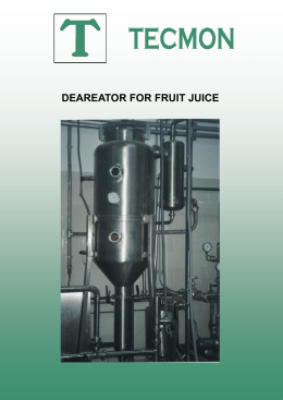
www.idealvac.com
Operating Instructions
(505)872-0037
VTB
Vacuum pumps
VTB (01)
O
L
M
VTB 180
N
VTB 250
F
VTB 340
F
B
E
VTB 500
A
E
F
E
F
�
S
W1
L
Pump ranges
These operating instructions concern the following dry running rotary vane vacuum pumps: Models VTB 180 to VTB 500.
Version (01)
➝
cooling air exits through slots on the fan housing
see pictures �
Version (31)
➝
cooling air exits out of the spiral housing
see pictures �
The vacuum capacities at atmosphere are 170, 250, 350 and 510 m3/hr operating on 50 cycles. The pumping curves showing
capacity against pressure can be found in data sheets:
D 267/ 1 ➝ VTB 180 - VTB 500 (01)
•
D 267/ 2 ➝ VTB 180 - VTB 500 (31)
Description
All models are complete with an inlet threaded connection and a silencer on the exhaust. All the air handled is filtered
by a built-in micro-fine filter. A high efficiency cooling fan that pulls air in is situated between the pump housing and the
motor. On version (01) the fan is located in the fan housing (see pictures �). The heated cooling air (F) is radially
exhausted out of the fan housing (W 1). On version (31) the fan is located in a spiral housing (see pictures �). In this
case the heated cooling air (F) can be directed either upwards or to the side depending on the position of the spiral
housing (W2). It is also possible to connect ducting to the spiral housing so that the cooling air (F) can be transported
away from the unit.
All the pumps are driven by a direct flanged three phase, standard TEFV motor via a pin and bush coupling.
Optional extras: As required, vacuum regulating valve (ZRV), non return valve (ZRK), inlet dust filter (ZFP), vacuum
tight suction filter (ZVF), motor starter (ZMS), softstarter (ZAD), unloading valve (ZAE), various vacuum gauges (ZVM)
and acoustic enclosure (ZBX).
BE 267
VTB (31)
O
B
F
L
M
N
1.8.2000
F
Werner Rietschle
GmbH + Co. KG
Postfach 1260
F
79642 SCHOPFHEIM
GERMANY
E
0 76 22 / 3 92-0
A
Fax 0 76 22 / 39 23 00
E
E-Mail: [email protected]
http://www.rietschle.com
Rietschle (UK) Ltd.
F
Bellingham Way
NEW HYTHE
KENT ME20 6XS
UNITED KINGDOM
E
0 16 22 / 71 68 16
�
Fax 0 16 22 / 71 51 15
W2
S
L
E-Mail: [email protected]
http://www.rietschle.co.uk
Suitability
VTB (01)
The units VTB are suitable for use in the industrial field
i.e. the protection equipment corresponds to EN DIN 294
c
table 4, for people aged 14 and above.
The VTB can be used for the evacuation of a closed system or for
a permanent vacuum from 200 to 1000 mbar (abs.).
The ambient and suction temperatures must be between
5 and 40° C. For temperatures outside this range please
contact your supplier.
These dry running vacuum pumps are suitable for use with air of a
relative humidity of 30 to 90 %.
Dangerous mixtures (i.e. inflammable or explosive gases
or vapours), extremely humid air, water vapour, aggressive gases or traces of oil and grease must not be handled.
a
The standard versions may not be used in hazardous areas. Special
versions with Ex-proof motors can be supplied.
Q
For all applications where an unplanned shut down of the
vacuum pump could possibly cause harm to persons or
installations, then the corresponding safety backup system must be installed.
�
Q
e
Q
T
Handling and Setting up
Pumps that have reached operating temperature may have a surface temperature at position (Q) of more than 70° C. WARNING!
Do Not Touch. (see pictures � and �)
The filter housing (S), exhaust box (T), housing cover (b) and greasing points (L) must all be easily accessible. For maintenance purposes we
recommend a space of 0.4 m in front of the filter housing and housing cover. The cooling air entries (E) and the cooling air exits (F) must have
a minimum distance of 20 cm from any obstruction. The discharged cooling air must not be re-circulated. If the cooling air exits from the spiral
housing (W2) via ducting, then care should be taken so that the passage of air is not obscured. (see pictures � to �)
The VTB pumps can only be operated reliably if they are installed horizontally.
For installations that are higher than 1000 m above sea level there will be a loss in capacity. For further advice please contact your
supplier.
When installed on a solid base, these pumps do not require fixing down. If the pumps are installed on a base plate we would recommend fitting
anti-vibration mounts. This range of vacuum pumps is almost vibration free in operation.
Installation (pictures � to �)
For operating and installation follow any relevant national standards that are in operation.
1.Vacuum connection at (A).
The air handled can be exhausted into the atmosphere through the exhaust port (B) or on models VTB (31) by directing the air through the spiral
housing (W2).
Long and/or small bore pipework should be avoided as this tends to reduce the capacity of the pump.
2. The electrical data can be found on the data plate (N) or the motor data plate. The motors correspond to DIN/VDE 0530 and have IP 54
protection and insulation class B or F. The connection diagram can be found in the terminal box on the motor (unless a special plug connection
is fitted). Check the electrical data of the motor for compatibility with your available supply (voltage, frequency, permissible current etc.).
3. Connect the motor via a motor starter. It is advisable to use thermal overload motor starters to protect the motor and wiring. All cabling used
on starters should be secured with good quality cable clamps.
We recommend that motor starters should be used that are fitted with a time delayed trip resulting from running beyond the amperage setting.
When the unit is started cold, over-amperage may occur for a short time.
The electrical installation may only be made by a qualified electrician under the observance of EN 60204. The main switch must
be provided by the operator.
Initial Operation (pictures � and �)
1. Initially switch the pump on and off for a few seconds to check the direction of rotation against the direction arrow (O).
Note: On this initial start the suction pipework should not be connected. If the pump runs backwards with the pipework connected
a pressure could build up within the housing which could result in damaged rotor blades.
2. Connect the suction pipe at (A).
For pipe work longer than 3 m we recommend using non-return-valves (ZRK), to avoid reverse rotation when the units are switched
off.
3. Vacuum regulating valve (optional extra):
The vacuum can be adjusted by turning the regulating valve (C) according to the symbols on the top of the regulating valve.
Potential risks for operating personnel
Noise Emission: The worst noise levels considering direction and
intensity (sound power), measured according to DIN 45635 part
3 (as per 3. GSGV), are shown in the table at the back. When
working permanently in the vicinity of an operating pump we
recommend wearing ear protection to avoid any damage to
hearing.
VTB (31)
Q
c
a
�
Q
e
Q
T
Maintenance and Servicing
When maintaining these units and having such situations where personnel could be hurt by moving parts or by live electrical parts, the pump
must be isolated by totally disconnecting the electrical supply. It is imperative
that the unit cannot be re-started during the maintenance operation.
Do not maintain a pump that is at its normal operating temperature as there is
a danger from hot parts.
1. Lubrication (pictures � to �)
The lubrication points are (L); lubrication periods are as follows, but the minimum is
once a year:
Operating hours
Grease
Model
50 Hz
60 Hz
every bearing
VTB
180
6.000
5.000
8g
VTB
250
6.000
4.500
8g
VTB
340
6.000
6.000
10 g
VTB
500
6.000
5.000
10 g
Note! These greasing instructions are valid for operation at 20° C ambient
temperature. At 40° C these should be reduced by 50 %.
We recommend the following grease types: Klüber PETAMO GY 193 or other equal
greases (see label of recommended greases (M)).
h
S
g
f
�
2. Air filtration (picture �)
The capacity of the pump may be reduced if the air inlet filters are not maintained correctly.
The filter cartridges (f) of the suction filter (S) have to be cleaned monthly and replaced once a year (under extreme conditions, more regularly).
Changing the filter: Loosen thumb screws (g). Take off filter cover (h) complete with gasket. Remove filter cartridges (f) and clean or exchange.
Re-assemble in reverse order.
3. Blades (pictures �, � and �)
Checking blades: The models VTB have 5 blades which have a low, but permanent, wear factor.
First check after 2,000 operating hours, thereafter every 500 operating hours.
Remove end cover (e). To remove the housing cover (b) from the housing the bolt (a) located in the centre of the bearing cover (c) should first
be removed. To achieve this, one of the fixing bolts (s) from the housing cover should be screwed into the thread in the centre of the bearing
cover (c). Remove the blades (d) and check. All blades must have a minimum height (X) of:
Model
X (minimum hight)
VTB 180
40 mm
VTB 250
52 mm
VTB 340
57 mm
VTB 500
57 mm
All blades must be changed at the same time.
Note! The VTB 500 has 2 blades per slot.
Changing blades: if the minimum height (X) is reached, then the whole set of rotor blades should be changed.
Before re-fitting the blades, blow out the housing and the rotor slots. Place the blades with the radius outwards (Y) such that the bevel is in the
direction of rotation (O1) and corresponds with the radius of the housing (Z).
Before re-fitting the housing cover (b), re-distribute the grease from the bearing cover (c) on to the appropriate bearing. It is important that the shaft
end is completely clean so that no grease can enter the housing, as this could mix with carbon dust and give a viscous paste which would result
in the blades becoming stuck in the rotor slots.
Note! Care should be taken that the bearing should not become contaminated.
When re-fitting the housing cover (b), tighten the bolts evenly so that the end cover fits correctly onto the fixing points. When the end cover is almost
touching the housing we recommend moving the fan in both directions whilst further tightening the bolts. This can be achieved by removing the
motor fan cover. This then ensures that the blades are sitting correctly in their slots and avoids any edge damage. Re-fit the end cover (e).
b
e
Y
Z
X
O1
�
d
s
5. Coupling (picture �)
The coupling rubbers (k) are wearing parts and should be checked regularly. When the coupling rubbers are worn this can be detected by a knocking
sound when the vacuum pump is started.
Defective coupling rubbers can cause extensive damage and even in some extreme cases break the rotor shaft.
To check the coupling, stop the motor (m) and isolate. Remove the screws (s5) on the motor flange (n). For motors secured by the feet, screws (s6)
should also be removed. Pull off the motor together with the motor side coupling half (q). If the coupling rubbers (k) are damaged, remove the
circlips (l) from the coupling bolt (r) and exchange the coupling rubbers (k). Leave the spacer (p) in place, check the coupling bolts (r) for any wear
and replace if necessary. To replace, remove the circlip (l1), pull off the coupling and fan (v) complete from the pumpshaft, remove the nut (w) with
washer (u) and exchange the coupling bolts.
Re-assemble in reverse order.
Trouble Shooting:
1. Motor starter cuts out vacuum pump:
1.1 Check that the incoming voltage and frequency corresponds with the motor
data plate.
1.2 Check the connections on the motor terminal block.
1.3 Pump is trying to operate against a closed exhaust or without an unloading
valve on start/delta starting.
Solution: Optional extra, unloading valve model ZAE.
1.4 Incorrect setting on the motor starter.
1.5 Motor starter trips too fast.
Solution: Use a motor starter with a time delay trip (version as per IEC 947-4).
1.6 Back pressure on the exhaust pipework is excessive.
2. Insufficient suction capacity:
2.1 Inlet filters are obscured.
2.2 Suction pipe work is too long or too small.
2.3 Leak on the pump or on the system.
2.4 Blades are damaged.
3. Vacuum pump does not reach ultimate vacuum:
3.1 Check for leaks on the suction side of the pump or on the system.
3.2 Blades are worn or damaged.
4. Vacuum pump operates at an abnormally high temperature:
4.1 Ambient or suction temperature too high.
4.2 Cooling air flow is restricted.
4.3 Problem as per 1.6.
5. Unit emits abnormal noise:
5.1 The pump cylinder is worn.
Solution: send your complete unit off for repair to the supplier or approved service agent.
5.2 The regulating valve (if fitted) is noisy.
Solution: replace valve.
5.3 Blades are damaged.
�
Appendix:
Repair on Site: For all repairs on site an electrician must disconnect the motor so that an accidental start of the unit cannot happen.
All engineers are recommended to consult the original manufacturer or one of the subsidiaries, agents or service agents. The address of the nearest
repair workshop can be obtained from the manufacturer on application.
After a repair or before re-installation follow the instructions as shown under the headings ”Installation and Initial Operation”.
Lifting and Transport: To lift and transport the vacuum pump the eye bolts on the housing and motor must be used. If an eye bolt is missing use
suitably rated strops. The weight of the pumps are shown in the accompanying table.
Storage: VTB units must be stored in dry ambient conditions with normal humidity. We recommend for a relative humidity of over 80% that the
pump should be stored in a closed container with the appropriate drying agents.
Disposal: The wearing parts (as listed in the spare parts lists) should be disposed of with due regard to health and safety regulations.
Spare parts lists:
E 267/ 1 ➝ VTB 180 - VTB 500 (01)
E 267/ 2 ➝ VTB 180 - VTB 500 (31)
VTB
Noise level (max.) /
Sound power*
Weight (max.)
dB(A)
kg
Length (max.)
mm
Width
mm
Height (max.)
mm
50 Hz
180
250
340
500
77
78
80
86 / 96*
60 Hz
79
80
84
89 / 99*
(01)
220
220
390
495
(31)
230
230
410
515
(01)
1073
1073
1243
1444
(31)
1072
1072
1243
1444
568
568
704
714
(01)
450
450
575
575
(31)
647
647
807
807
11.2000 / PM6
Daten
Vakuumpumpen
Vacuum pumps
Pompes à vide
VTB (01)
Pompe per vuoto
VTB 180 (01)
VTB 250 (01)
VTB 340 (01)
VTB 500 (01)
[mm]
A
B
C
E
F
L
M
N
O
Vakuum-Anschluß
Abluft-Austritt
Vakuum-Begrenzungsventil
Kühlluft-Eintritt
Kühlluft-Austritt
Schmierstellen
Schmierschild
Datenschild
Drehrichtungsschild
VTB (01)
[mm]
a
a1
b
c
d
e
f
g
h
k
l
m
n
o
r
øs
t
u
øw
R
Vacuum connection
Exhaust
Vacuum limitation valve
Cooling air entry
Cooling air exit
Greasing points
Greasing label
Data plate
Direction of rotation
180
1073
668
568
450
193
430
300
355
240
360
181
506
292
276
268
18
M 32 x 1,5
30
246
G 21/2
250
1073
668
568
450
193
430
300
355
240
360
181
506
292
276
268
18
M 32 x 1,5
30
246
G 21/2
Raccord du vide
Refoulement
Limiteur de dépression
Entrée air refroidissement
Sortie air refroidissement
Points de graissage
Etiquette graissage
Etiquette caractéristique
Flèche sens rotation
340
1243
726
704
575
201
415
380
463
310
440
221
515
361
343
268
20
M 40 x 1,5
40
312
G3
Attacco vuoto
Scarico aria
Valvola regolazione vuoto
Entrata aria di raffreddamen.
Uscita aria di raffreddamento
Punti di lubrificazione
Targhetta della lubrificazione
Targhetta dati
Targhetta senso rotazione
500
1444
866
714
575
203
485
380
463
310
440
221
585
361
353
338
20
M 40 x 1,5
40
360
G3
D 267/ 1
1.2.2000
Werner Rietschle
GmbH + Co. KG
Postfach 1260
79642 SCHOPFHEIM
GERMANY
0 76 22 / 3 92-0
Fax 0 76 22 / 39 23 00
E-Mail: [email protected]
http://www.rietschle.com
VTB (01)
180
170
200
50 Hz
60 Hz
m3/h
250
250
300
mbar (abs.)
kW
A
min-1
dB(A)
Hz
Hz
Hz
Hz
Hz
Hz
Hz
Hz
Hz
Hz
230/ 400 V ± 10%
220/ 380V
4,0
4,8
16,9 / 9,8
22,5 / 13,0
15,0
18,0
30,0 / 17,3
#
78
82
390
81
83
495
74
76
220
25/ 0
25/ 0
50/0
50/0
65 (03) / 216 (51)
65 (03) / 216 (51)
80 (03) / 216 (52)
80 (03) / 216 (52)
65 (02)
65 (02)
65 (03) / 100 (01)
100 (01)
200 / 100
160 / 100
250 / 160
- / 200
250 / 160
200 / 100
- / 160
#
Baugrößen auf Anfrage / Size on request / Taille selon demande / Dimensioni su richiesta
50 / 60 Hz
50 Hz
60 Hz
ZAD / ZAE / ZBX
ZMS
ZRV
ZRK
ZFP
ZVF
ZMS
ZAD
ZAE
ZBX
5,5
6,5
14,5 / 8,4
17,0 / 9,8
72
75
220
kg
mbar (abs.)
3~
kW
A
min-1
dB(A) ➝ DIN 45635
kg
400/ 690 V ± 10%
380/ 660V
11,0
13,0
22,5 / 13,0
17,0 / 9,8
950
1140
ZRV
ZRK / ZFP
ZVF
m3/h
mbar (abs.) •
500
510
600
200
50
60
50
60
50
60
50
60
50
60
3~
340
350
410
Saugvermögen
Endvakuum
(im Dauerbetrieb)
Ansaugdruck
Motorausführung
Motorleistung
Stromaufnahme
Drehzahl
Mittlerer Schalldruckpegel
Max. Gewicht
Zubehör
Vakuum-Regulierventil
Rückschlagventil
Vakuumdichter Staubabscheider
Vakuumdichter Ansaugfilter
Motorschutzschalter
Sanftanlauf
Anlaufentlastung
Schallbox
Capacity
Ultimate vacuum
(on continuous operation)
Suction pressure
Motor version
Motor rating
Current drawn
Speed
Average noise level
Maximum weight
Optional extras
Vacuum regulating valve
Non-return valve
Dust separator vacuum tight
Vacuum tight suction filter
Motor starter
Soft starter
Unloading valve
Acoustic enclosure
50 Hz
m³/h*
Débit
Vide limite
(en fonctionnement continu)
Pression d'aspiration
Exécution moteur
Puissance moteur
Intensité absorbée
Vitesse rotation
Niveau sonore moyen
Poids maxi.
Accessoires
Valve réglage vide
Clapet anti-retour
Filtre séparateur étanche
Filtre d'aspiration étanche
Disjoncteur moteur
Démarrage progressif
Décharge de démarrage
Caisson insonorisant
Portata
Vuoto finale
(in funzionamento continuo)
Pressione di aspirazione
Esecuzione motore
Potenza motore
Corrente nominale
Numero giri
Rumorosità media
Peso massimo
Accessori
Valvola regolazione vuoto
Valvola di non ritorno
Separatore polveri ermetico
Filtro aspirazione ermetico
Interruttore magnetotermico
Soft starter
Avviamento a vuoto
Box insonorizzante
60 Hz
m³/h*
700
700
100
100
500
500
340
340
250
250
180
180
10
10
1
1
0
200
400
600
800
1000
mbar (abs.)
0
200
400
600
800
1000
mbar (abs.)
* bezogen auf den Zustand im Sauganschluß./ related to suction conditions at inlet connection./ relatif à l'état règnant à l'aspiration./ riferito alle condizioni in aspirazione.
Kennlinien und Tabellenangaben beziehen sich auf betriebswarme Vakuumpumpen./ Curves and tables refer to vacuum pump at normal operating temperature./ Les courbes et
tableaux sont établies, pompe à température de fonctionnement./ Le curve caratteristiche ed i dati riportati nelle tabelle si riferiscono alle pompe per vuoto con funzionamento a regime.
Technische Änderungen vorbehalten!/ We reserve the right to alter technical information!/ Sous réserve de modification technique!/ Salvo modifiche tecniche!
Die Abmessungen a und ø w sowie die Stromaufnahme können je nach Motorfabrikat von den hier aufgeführten Angaben abweichen./ The dimensions a and ø w and /or the current
drawn can differ when compared with the data list, depending on the motor type./ Les dimensions a et ø w ainsi que l'ampérage peuvent différer des données indiquées ci-dessus, selon
le fabricant du moteur./ Le dimensioni a e ø w come la corrente nominale possono scostarsi leggermente dai dati qui riportati a seconda del costruttore del motore.
# auf Anfrage
# on request
# sur demande
# a richiesta
2.2001 / PM6
VTB 180 (01) –> VTB 500 (01)
73
84
74
70
71
57
11
69
59
61
56
58
60
62
26
68
10
25
9
22
55
63
67
8
103
7
112
32
19
3
18
111
20
90
5
31
21
88
110
89
87
104
2
66
50
65
101
100
12
49
27
22
91
23
24
5
1
VTB
40
96
39
46
36
92
102
37
41
Rie
tsc
MA
CR
47
44
45
E 267/1
2.2.99
14
15
38
O
43
17
13
42
hle
32
105
18
VTB 180 (01) –> VTB 500 (01)
Grundeinheit
Basic unit
Unité de base
Elemento base
1
Gehäuse
Housing
Corps
Corpo pompa
Blasluftseite
2
Rotor
Rotor
Rotor
Rotore
55
Ausblasventil komplett
3 V
Lamelle
Blade
Palette
Paletta
56
Innen-Sechskantschraube
Allen screw
Vis 6 pans creuse
Vite a brugola esagonale
5
Gehäusedeckel
Housing cover
Couvercle de corps
Coperchio corpo pompa
57
Federteller
Spring plate
Disque ressort
Piatto elastico
7
Abdeckring' A
Cover ring' A
Cache' A
Anello di protezione' A
58
Druckfeder
Spring
Ressort
Molla a pressione
8 V
Rillenkugellager
Deep groove ball bearing
Roulement aiguille
Cuscinetto a sfera
59
Ventilkörper
Valve body
Corps valve
Corpo valvola
9
50
Vakuum-Begrenzungsventil
Vacuum limitation valve
Limiteur de dépression
Valvola regolazione vuoto
Pressure side
Côté refoulement d'air
Lato soffieria
Exhaust valve complete
Soupape refoulement cpl.
Valvola di scarico completo
Spannmutter
Clamping nut
Ecrou tendeur
Manicotto di serraggio
60
Rohr
Pipe
Tuyau
Tubo
10 D
INA-Dichtring
INA-seal ring
Joint d'arbre INA
Anello di tenuta INA
61 D
Ventilscheibe
Valve disc
Rondelle valve
Rondella della valvola
11
Lagerdeckel' A
Bearing cover' A
Couvercle de roulement' A
Coperchio cuscinetti' A
62
Ventilscheibe
Valve disc
Rondelle valve
Rondella della valvola
12 V
Sicherungsring
Lock ring
Circlip
Anello di sicurezza
63
Ventilplatte
Valve plate
Plaque valve
Piastra della valvola
13 V
Sicherungsring
Lock ring
Circlip
Anello di sicurezza
65 D
Dichtung
Gasket
Joint
Guarnizione
14
Abdeckring' B
Cover ring' B
Cache' B
Anello di protezione' B
66
Zwischenkasten
Intermediate box
Boîte intermediare
Scatola intermedia
15 V
Zylinder-Rollenlager
Cylinder roller bearing
Roulement rouleaux cylindr. Cuscinetto a rotolamento
67 D
Dichtung
Gasket
Joint
Guarnizione
17
Lagerdeckel' B
Bearing cover' B
Couvercle de roulement' B
Coperchio cuscinetti' B
68
Ausblasgehäuse
Exhaust box
Carter refoulement
Scatola filtro
18
Trichterschmiernippel
Grease nipple
Graisseur
Ingrassatore
69 D
Dichtring
Sealing ring
Anneau d'étanchéité
Anello di tenuta
19
Paßfeder
Key
Clavette
Chiavetta
70 D
Dichtung
Gasket
Joint
Guarnizione
20
Verschlußschraube
Lock plug
Bouche obturateur
Vite di chiusura
71
Filterdeckel
Filter cover
Couvercle filtre
Coperchio del filtro
21
Scheibe
Disc
Rondelle
Disco
73
Bogen
Bend
Coude
Curva
22
Rohrleitung
Pipe line
Tuyauterie
Tubazione
74
23
Hohlschraube
Banjo bolt
Vis creuse
Vite forata
24 D
Dichtring
Sealing ring
Anneau d'étanchéité
Anello di tenuta
25
Hohlschraube
Banjo bolt
Vis creuse
Vite forata
26 D
Dichtring
Sealing ring
Anneau d'étanchéité
Anello di tenuta
27
Zylinderstift
Dowel pin
Goujon cylindrique
Spina cilindrica
31
Ringschraube
Lifting eye
Anneau de levage
Golfare
32 D
Geräuschdämpfer komplett
Silencer complete
Silencieux complet
Silenziatore completo
Kühlung
Cooling
Refroidissement
Raffreddamento
84
Ventilatorhaube
Fan cover
Capot ventilateur
Calotta del ventilatore
87
Kupplungsbolzen
Coupling bolt
Plot d'accouplement
Perno del giunto
88
Distanzring
Spacer ring
Rondelle entre-toise
Anello distanziatore
89 V
Kupplungsgummi
Coupling rubber
Caoutchouc d'accouplem.
Gommino del giunto
90 V
Sicherungsring
Lock ring
Circlip
Anello di sicurezza
Wellendichtring
Shaft seal
Joint d'arbre
Anello di tenuta sull' albero
91
Abschlußdeckel
End cover
Couvercle
Coperchio di chiusura
Saugluftseite
Suction side
Côté aspiration
Lato aspirazione
92
Scheibe
Disc
Rondelle
Disco
36 D
Dichtung
Gasket
Joint
Guarnizione
96
37
Filtergehäuse
Filter housing
Carter filtre
Scatola del filtro
38
Schaftschraube
Shaft screw
Vis calibrée
Vite prigioniera
39 D
Dichtung
Gasket
Joint
Guarnizione
40
Papierfilter komplett
Paper filter complete
Filtre papier complet
Filtro in carta completa
41 D
Dichtring
Sealing ring
Anneau d'étanchéité
Anello di tenuta
42 V
Micro-Top-Patrone.
Filter cartridge
Cartouche filtre
Cartuccia filtrante
43
Senkschraube
Countersunk screw
Vis à tête conique
Vite a testa svasata
44 D
Dichtung
Gasket
Joint
Guarnizione
45
Filterdeckel
Filter cover
Couvercle filtre
Coperchio del filtro
46
Kegelfeder
Coil spring
Ressort
Ventilator/Kupplung kpl.
Fan/coupling cpl.
Ventilateur/accouppl. cpl.
Ventilatore/giunto compl.
Antrieb
Drive
Entraînement
Azionamento
100
Kupplungshälfte treibend
Coupling half driving
Demi-accouplement moteur Semigiunto lato motore
101
Motorflansch
Motor flange
Bride moteur
102
Fuß
Foot
Socle
Piedistallo
103
Motor
Motor
Moteur
Motore
104
Gewindestift
Threaded pin
Vis pointeau
Spina filettata
105
Fußpolster
Rubber foot
Plot antivibratoire
Piedini antivibranti
Schilder
Labels
Plaques signalétiques
Targhette
Molla conica
110
Datenschild
Data plate
Etiquette caractéristique
Targhetta dati
Schmierschild
Greasing label
Etiquette graissage
Targhetta della lubrificazione
Pfeilschild
Direction arrow
Sens de rotation
Freccia senso di rotazione
47
Filterschraubknopf
Filter knob
Tête molette
Pomello a vite
111
49 D
Dichtring
Sealing ring
Anneau d'étanchéité
Anello di tenuta
112
Bei Bestellungen folgendes angeben: Typ, Fabrikations-Nr., Positions-Nr., Motor (kW, V, Hz)
To order please indicate: model, serial-no., item-no., motor (kW, V, Hz)
En cas de commande préciser: type d'appareil, no. de position des pièces, moteur (kW, V, Hz)
Nell'ordine indicare: tipo, numero di matricola, numero di posizione dei ricambi, motore (kW, V, Hz)
V = Verschleißteile
V = Wearing parts
V = Pièces d'usure
V = Parti usurabili
D = Dichtungen
D = Seals
D = Joints
D = Guarnizioni
Flangia motore
Werner Rietschle GmbH + Co. KG
Postfach 1260 • D-79642 Schopfheim
07622 / 392-0 • Fax 076 22 / 392300
e-mail: [email protected]
3.2000 / PM6
Scaricare